
BIM Standards
City of Seattle BIM Standards
TA B L E O F C O N T E N T S
28/30/2024 City of Seattle BIM Standards
SECTION 1: Information
• 1.0 Introduction
• 1.1 Glossary of Terms
• 1.2 Civil Integrated Management (CIM)
• 1.3 Information Models
SECTION 2: Requirements
• 2.0 BIM Requirements
• 2.1 Software Versions & Licensing Options
• 2.2 BIM Execution Plan
• 2.3 BIM Project Setup
SECTION 3: Project Templates & Dependencies
• 3.0 TrueType Font
• 3.1 Color Tables
• 3.2 Civil Model Templates & Layers
• 3.3 Facility Model Templates & Layers
• 3.4 Sheet (Title Block) Templates
SECTION 4: Drawing Standards
• 4.0 Drawing Standards
• 4.1 Annotation Standards
• 4.2 Hatch Pattern Standards
• 4.3 Design Change Standards
• 4.4 Record Drawing Standards
SECTION 5: Project Deliverable Guides
• 5.0 Project Deliverable Checklist
• 5.1 Publish Plan Sheets
• 5.2 Facility Asset Information Models
• 5.3 Publish GIS Data

BIM Standards
SECTION 1: Information
38/30/2024 City of Seattle BIM Standards

1 . 0 I N T R O D U C T I O N
8/30/2024 City of Seattle BIM Standards 4
What is BIM?
Building Information Modeling (BIM) is a process of planning and collaboration for construction projects that is
facilitated by modern digital technology on a Common Data Environment that provides integrations with other
systems like geographic information systems (GIS) and enterprise asset management (EAM) systems.
BIM supports project development, inter-departmental planning, and key asset data tracking and integration.
Managing documents in a BIM document management system (Common Data Environment) has the following
benefits:
• Easy access to design and construction documents in a centralized repository
• Document versioning
• Model coordination and clash detection
• Design and construction issue and markup tracking
• Design and construction document approvals
Purpose of Document
This document has been written to communicate requirements for City of Seattle project teams who are
implementing BIM workflows and technology in-house and in partnership with consultants, contractors, and other
agencies. For a list of updates, see change log.
1 . 1 G LO S S A R Y O F T E R M S
8/30/2024 City of Seattle BIM Standards 5
Here are some common terms that will be used throughout this document:
• BIM Execution Plan (BIMxp): A BIM Execution Plan is a project support document generated by the City of
Seattle to track assets and activities and facilitate data coordination by generating tailored project BIM standards.
• PTN: “Project Tracking Number”, defined in the BIMxp.
• VPI: “Vault Plan Index” number, acquired from the City of Seattle Records Vault (SeaDIR).
• Civil Integrated Management (CIM): Method of integrating technology and managing data across systems.
• Common Data Environment (CDE): the platform that the City of Seattle uses for project collaboration and
delivery is Autodesk Docs® on the Autodesk Construction Cloud®.
• Coordinate System (CS): The Citywide standard coordinate system is HPGN (HARN) Washington State Planes,
North Zone, US Foot (code: HARN/WO.WA-NF; EPSG code: 2926).
• Information Models: Intelligent 3D models, such as Civil 3D® objects (Pipe/Pressure Networks, Feature Lines,
Surfaces, Cogo Points, etc.), and Revit® and AutoCAD Plant 3D® models.
• Project Deliverables: The following deliverables are required, if defined in the project BIMxp:
• PDF sheets: Plan sheets published in PDF format (must use COS-ROMANS.TTF).
• Project Asset List (PAL): “Vertical” (facility) asset list, per the BIMxp.
• NWD models: Federated 3D information models published in NWD format with materials applied.
• ArcGIS® data: Geospatial “horizontal” (linear/conveyance) asset object data published to ArcGIS®.

1 . 2 C I V I L I N T E G R AT E D M A N A G E M E N T ( C I M )
8/30/2024 City of Seattle BIM Standards 6
Civil Integrated Management (CIM) provides strategic
planning and support to improve and accelerate project
delivery across City of Seattle departments. The goal is to
align systems and data to support desired business
outcomes through standards and governance.
BIM standards provide the framework to support CIM by
integrating technology and data through the following
teams:
• Geographic Information Systems (GIS)
• Surveying and Mapping
• Engineering
• Construction
The map shown on the right illustrates how civil data is
published and made available on the GIS platform for
planning and analysis. It also cross-references the BIMxp
for technical requirements, the PTN to access source
surveying and engineering data, and the VPI for archived
plan sets.


1 . 3 . 1 H O R I ZO N TA L & V E R T I C A L U T I L I T Y I N F O R M AT I O N M O D E L S
“Vertical” assets are
located inside a facility.
“Horizontal” (linear/conveyance) assets* created
from Pipe or Pressure Networks connect to
vertical assets located inside a facility.
Civil 3D®
Plant 3D®
8/30/2024 City of Seattle BIM Standards 8
Applications used for creating utility information models include Autodesk Civil 3D®, Revit®, and AutoCAD Plant 3D®.
*additional geospatial assets are created with Cogo Points (symbols) and Feature Lines (linear features) to be published to GIS.

1 . 3 . 2 T R A N S P O R TAT I O N I N F O R M AT I O N M O D E L S
9
Autodesk Civil 3D® is used for creating transportation information models.
8/30/2024 City of Seattle BIM Standards
Civil 3D®
Cogo Points and Feature Lines
are used to create symbols and
linear features to be published
to GIS.
Map 3D®
Blocks and linework are
added for roadway
channelization markings.
Corridors, Grading Objects, 3D
solids, etc. are used to generate
transportation structures, surfaces,
and material layers.

1 . 3 . 3 M O D E L I N T E G R AT I O N S
10
Information models integrate with Geographic Information Systems (GIS) & Enterprise Asset Management Systems (EAMS).
8/30/2024 City of Seattle BIM Standards
GIS
ArcGIS Pro
Data Editor
BIM Models
Data Sync
ArcGIS Portal
Civil 3D Data (horizontal assets)
SeaDIR
PDFs
Autodesk Tandem
Plant 3D or Revit Data (vertical assets)
Tandem Connect
(project data)

BIM Standards
SECTION 2: Requirements
8/30/2024 City of Seattle BIM Standards 11

2 . 0 B I M R E Q U I R E M E N T S
12
1. Coordinate System: A coordinate system (CS) must be assigned to all geospatial drawings and a common origin prism
must be tied to the CS in facility models. The City of Seattle utilizes the standard HPGN (HARN) Washington State Planes,
North Zone, US Foot (EPSG code: 2926) grid CS. If a ground CS is utilized on your project, it must be documented so the
data can be transformed back to the standard grid CS.
2. Common Data Environment: The project must be setup on Autodesk Docs® in coordination with the City of Seattle.
a) Autodesk Desktop Connector version updates must be coordinated with the project team.
b) Autodesk BIM Collaborate Pro is required for team members who create and manage project data.
3. Project Deliverables: Software must be able to produce deliverables defined in the BIMxp, including:
a) PDF sheets of plan set (must use COS-ROMANS.TTF), per 5.1.
b) Project Asset List (PAL) for vertical (facility) assets, per 5.2.1.
c) Federated 3D model in NWD format of utility and facility information models, per 5.2.2.
d) Publish the following horizontal (linear/conveyance) assets with Autodesk Connector for ArcGIS, per 5.3:
8/30/2024 City of Seattle BIM Standards
Drainage and Wastewater (DWW):
Civil 3D® Pipe Networks and Feature Lines
Water System:
Civil 3D® Feature Lines and Cogo Points
Electrical Site:
Civil 3D® Feature Lines and Cogo Points
Roadway Paving:
Civil 3D® Feature Lines
Roadway Channelization:
AutoCAD Map 3D® Lines and Blocks
Curb Ramps:
Civil 3D® Feature Lines
Roadway Signalization:
Civil 3D® Feature Lines and Cogo Points
Lighting Site:
Civil 3D® Feature Lines and Cogo Points
Roadway Signage:
Civil 3D® Cogo Points
Trees:
Civil 3D® Cogo Points
Irrigation System:
Civil 3D® Feature Lines
and Cogo Points

2 . 0 . 1 a B I M B E S T P R A C T I C E S ( 1 O F 2 )
8/30/2024 City of Seattle BIM Standards 13
Steps for Successful Project Delivery
• Go over the submittal checklist to ensure standards compliance before submitting deliverables for review.
• Become familiar with the CDE, Autodesk Docs®, and how to track issues and conduct reviews on the platform.
• Learn how to conduct design collaboration and model coordination on the CDE.
Keep Drawings Clean
Be aware that inserting drawings and non-standard blocks may introduce clutter that affects drawing performance.
• In Civil 3D®, look for extraneous sites in the prospector and extended data in object properties.
• Purge unneeded layers, blocks, text styles, etc.
Proactive Approach to Projects
The goal is to be proactive, efficiently creating deliverables while reducing mistakes. A reactive approach costs more
money and may cause more errors due to last-minute edits and changes.
The graph on the next page illustrates how taking a reactive approach tends to cause delays and is prone to errors,
where-as taking a proactive approach helps teams produce targeted deliverables on time with less errors.

2 . 0 . 1 b B I M B E S T P R A C T I C E S ( 2 O F 2 )
8/30/2024 City of Seattle BIM Standards
30%
60%
90%
100%
10%
25%
50%
100%
0%
50%
100%
150%
30% Submittal 60% Submittal 90% Submittal 100% Submittal
Proactive Drawing Production Reactive Drawing Production
14
The orange line in the chart shows a reactive approach,
doing minimum work early on and delaying important
design tasks to the end of the project. Problems with this
approach include:
• Considerable work is left to the end of the project,
often resulting in mistakes and schedule delays.
• Shortcuts are taken to save time, reducing the data
quality.
• The project is prone to more change orders and
design changes during construction.
The blue line in the chart shows a proactive approach,
producing targeted deliverables on time. The proactive
approach aims to complete the following work at
standard milestones:
• Pre-30%: Develop a 3D base map with researched or
verified depths of underground utilities that may cause
conflicts during design.
• 30%: Develop sheet index table, create named plan
views and set match line locations for all disciplines in
the X-VIEW drawing and setup sheets.
• 30%: Create 3D models of proposed features for clash
detection and analysis (model coordination).
• 60%: Continue model coordination, determine
proposed elevations, and create profiles and/or
sections.
• 90%: Continue model coordination. Plan set must have
all the elements of the final plan set and only minor
changes should be made to reach 100%.

2 . 1 S O F T W A R E V E R S I O N S & L I C E N S I N G O P T I O N S
8/30/2024 City of Seattle BIM Standards 15
Autodesk Desktop Application Version Requirements
• Projects initiated between 10/31/2022 and 10/31/2024 must use the 2023 version of Autodesk applications.
• Projects initiated on or after 11/1/2024 must use the 2025 version of Autodesk applications.
• For Autodesk Desktop Connector version coordination information, see Section 2.3.4.
Autodesk Licensing (bring your own license model)
Autodesk Docs® (available with the Autodesk AEC Collection®), Autodesk BIM Collaborate Pro®, and Autodesk
desktop software are available on an annual or monthly basis or with Autodesk Flex licensing to pay as you go.
Esri ArcGIS® Licensing (City of Seattle provides accounts to publish geospatial data to ArcGIS®)
City of Seattle Internal Staff
Account Setup Form
External Partners
Account Application Form

2 . 2 B I M E X E C U T I O N P L A N ( B I M x p )
8/30/2024 City of Seattle BIM Standards 16
A BIM Execution Plan (BIMxp) documents specific information
modeling requirements for a project. City of Seattle project
leads (internal staff) must generate a BIM Execution Plan and
make modifications in coordination with the project team.
BIM Execution Plans (sharepoint.com)
BIM Execution Plans gives the ability to right-size project
requirements and they are important for three primary reasons:
1. project delivery (planning and coordination)
2. asset management (key asset publishing and integration)
3. as-built tracking (coordination and compliance)

2 . 2 . 1 B I M E X E C U T I O N P L A N C O N T E N T S
8/30/2024 City of Seattle BIM Standards 17
The BIMxp must contain the following content to define project requirements:
• Project Information
• List of team contributors, including the BIM Manager (Project Administrator), PM, PE, and Model Element Authors (MEAs)
• Model Progression Matrix defining the required information models and the levels of development
• Common Data Environment (CDE) requirements
• Team learning recommendations
• Civil infrastructure information modeling requirements
• Coordinate system
• Existing conditions modeling requirements
• Proposed modeling requirements
• Key asset types to be published to GIS
• Vertical asset information modeling requirements (if applicable)
• Project coordination requirements
• Deliverables
Once the project is setup, save the draft BIMxp to the project; see Section 2.3.2

2 . 2 . 2 B I M E X E C U T I O N P L A N W O R K F LO W S
8/30/2024 City of Seattle BIM Standards 18
A BIM Execution Plan (BIMxp) is a project communications tool:
• A BIMxp is created to communicate documented project requirements with the project team.
• Seattle IT sends communications to BIMxp authors about updates to software versions and centralized support files.
• Seattle IT sends automated quarterly check-in notifications to BIMxp authors to remind about publishing geospatial
data to GIS at required milestones.
1 ) P R O J E C T I N I T I A T I O N
A. Project initiator creates the draft
BIMxp.
B. A BIM Manager (project administrator)
is assigned to the project.
C. The BIM Manager acquires PTN and
documents it in the BIMxp.
D. The BIM Manager sets up the project
on the CDE and adds team members.
E. The BIM Manager works with the
project manager and project engineer
to document special requirements in
the BIMxp.
F. The BIM Manager communicates
project requirements with project
team (orientation meeting).
2 ) P R O J E C T D E L I V E R Y
A. The project team publishes PDFs for
milestone reviews as documented in
the BIMxp.
B. A Vault Plan Index (VPI) number is
acquired at the 60% milestone and is:
I. documented in the BIMxp
II. added to the sheets
III. added to the geospatial
drawing properties (command:
DWGPROPS)
C. The project team publishes geospatial
data to GIS at milestones documented
in the BIMxp.
D. The BIM Manager transmits PDFs to
SeaDIR and the construction team.
3 ) P R O J E C T C L O S E O U T
A. The project team documents revisions,
addendums, change orders, etc.
B. The project team transmits snapshot of
sheets (and references) to the
Y-RecordDWGs folder and disconnects
reference templates.
C. The construction team creates as-built
redlines and sends to project team.
D. The project team updates Record
Drawing PDFs (and federated models, if
applicable) and sends to SeaDIR.
E. The project team publishes as-built
geospatial data to GIS.
F. The BIM Manager marks the BIMxp as
“complete”.

2 . 3 B I M P R OJ E C T S E T U P
8/30/2024 City of Seattle BIM Standards 19
BIM Managers (project admins) have rights to create and
manage projects in the CDE: the Autodesk Construction
Cloud® (ACC) under the City of Seattle account.
Project Template
All projects must be created using the ACC template
called BIM-Project. The required project fields are
illustrated below:
Project names must be as short a possible, prefixed with
the Project Tracking Number (PTN) as defined in the
BIMxp.
The project administrator must:
• Review the members list (external partners must fill out
this form to be added to the City of Seattle ACC hub).
• Invite project team members and assign one of these
roles to each member (more info):
• BIM Manager (project administrator)
• Drafter
• Engineer
• IT (account administrator)
• Project Manager
• Reviewer
• Surveyor
• Bridge the W-Support folder to the Civil project files
folder and assign permissions for team member roles
to access.
PTN (SDOT: TRCXXXX, SPU: 261-XXXX)
SDOT: Streets/Roads/Highways, SPU: Utilities

2 . 3 . 1 “ B R I D G E ” S U P P O R T F O L D E R
8/30/2024 City of Seattle BIM Standards 20
To provide the required resources for a project, the BIM
Manager (project admin) must “bridge” the W-Support
folder to their Civil project files folder.
1. Go to the COS-Support project and navigate to:
Docs → Files → Project Files
2. Share the W-Support folder…
…to “another project” as shown on the right.
a) Check the “automatically sync updates to
target project” box.
b) Select the destination project.
c) Select the project’s “Project Files” folder.
Do not click “add folders” to
select and share sub-folders

2 . 3 . 2 “ B R I D G E ” B I M E X E C U T I O N P L A N T E M P L AT E
8/30/2024 City of Seattle BIM Standards 21
The BIM Manager must generate the BIM Execution Plan
and make it available to the project team.
1. Go to the COS-Support project and navigate to:
Docs → Files → Project Files → Shared → BIMxp
2. Inside the BIMxp folder, browse to find BIMxp.docx
and share it to “another project” as shown on the
right.
a) Select the destination project.
b) Select this folder:
Project Files → B-Shared → 02-TechMemos
3. Open BIMxp.docx and click the Edit button in the
upper-right corner:
and paste the draft BIM Execution Plan into the
document.
4. Work with the project manager and engineer to make
edits to the BIMxp document and share it with the
project team.

2 . 3 . 3 “ B R I D G E ” R E M OT E S E N S I N G D ATA ( O P T I O N A L )
8/30/2024 City of Seattle BIM Standards 22
There are MrSID images (each image comes with a .sid,
.sid.xml, and .sid.aux.xml files), and Lidar point cloud files
(in .las format) available for projects.
At any time during the project, the BIM Manager (project
admin) may “bridge” remote sensing and/or imagery data
to their …\B-Shared\03-Data folder to be used by project
team members (each sub folder also contains a drawing
index for reference – bridge it first to locate image files).
1. Go to the COS-Support project and navigate to:
Docs → Files → Project Files → Data
2. Inside the Data folder, browse to the correct files,
select them, and share them with “another project” as
shown on the right.
a) Select the destination project.
b) Select this folder:
Project Files → B-Shared → 03-Data
3. Let the project team know the data files are available
to use.

2 . 3 . 4 A U TO D E S K D E S K T O P C O N N E C T O R
8/30/2024 City of Seattle BIM Standards 23
The BIM Manager must make sure project team members have the same version of Autodesk Desktop Connector®
(version 16+) and work with Seattle IT to ensure that updates are applied to everyone at the same time.
Autodesk Desktop Connector® must be configured to prevent reference templates from being uploaded to Autodesk
Docs when using Autodesk Collaboration for Civil 3D®.
Team members must also utilize the same compatible versions of desktop applications and upgrade at the same time.
Seattle IT will notify BIMxp authors about upcoming software updates so they can coordinate with their project teams.
City of Seattle Project Folder Root
C:\Users\%USERNAME%\DC\ACCDocs\City of Seattle\[project]\Project Files\...
(from this point on, folder paths will be shown after this root folder level)

2 . 3 . 5 M E M B E R R O L E S
24
Project members have defined roles that are tied to folder permissions:
• BIM Manager: full control of all folders (project administrator)
• Consultant: view all folders (permissions applied by company on specific sub-folders)
• Contractor: view/download/upload and create issues/markups in the B-Shared folder
• Drafter: view/download all folders and full control of the C-Civil/03-Design folder/sub-folders
• Engineer: view/download all folders and full control of the C-Civil/03-Design/…/WIP folder
• IT: full control of all folders (account administrator)
• Project Manager: view/download all folders and create issues/markups within most sub-folders
• Reviewer: view all folders and create issues/markups within most sub-folders
• Surveyor: view/download all folders and full control of C-Civil/02-Survey folder/sub-folders
8/30/2024 City of Seattle BIM Standards

2 . 3 . 6 a S U P P O R T F I L E S F O R E X T E R N A L PA R T N E R S ( 1 O F 2 )
8/30/2024 City of Seattle BIM Standards 25
Support File Search Path
For external team members to utilize the City of Seattle custom linetypes, each person must sync this folder location
(right-click and select “always keep on this device”) in Autodesk Desktop Connector®:
…\W-Support
Then, in Civil 3D® or AutoCAD®, run the Options command, switch to the “Files” tab, select “Support File Search Path”
and click the “Add…” button to add the W-Support folder path shown above.
Plot Style Table for Batch Plotting
When batch plotting sheets, team members will need to configure Civil 3D® or AutoCAD® to access to the CTB
stored in the following folder:
…\W-Support
In Civil 3D® or AutoCAD®, run the Options command, switch to the “Files” tab, expand “Printer Support File Path”,
select “Plot Style Table Search Path” and click the “Add…” button to add the W-Support folder path shown above.

2 . 3 . 6 b S U P P O R T F I L E S F O R E X T E R N A L PA R T N E R S ( 2 O F 2 )
8/30/2024 City of Seattle BIM Standards 26
Installable Content
Additional support content is available online at https://www.seattle.gov/tech/bim
• TrueType Font
• Survey Figure Prefix Library
• Survey Line Code Set
• Civil 3D® Pipe and Pressure Network Catalogs
• Civil 3D® plugins (latest versions are compatible with the required version of Autodesk desktop applications)

2 . 3 . 7 a P R OJ E C T F O L D E R S A N D F I L E R E F E R E N C I N G ( 1 O F 2 )
8/30/2024 City of Seattle BIM Standards 27
The BIM Manager (project admin) must confirm that
members are added with proper roles (permissions are
inherited from roles) and that the project folders are
setup. Common folders are shown below; additional
folders may be created for Revit® and/or AutoCAD Plant
3D® as needed.
XREFs and DREFs
Drawings must be saved in the following locations:
• Authoritative survey drawings:
…\C-Civil\02-Survey\D-XREF
• Authoritative design drawings:
…\C-Civil\03-Design
It is permitted to create sub folders if needed during project
setup, but the changes must be communicated with the
project team. Utilize the WIP sub folder for works in progress.
Civil 3D Data Shortcuts
The Autodesk BIM Collaborate Pro® entitlement is required to
setup Civil 3D® data shortcuts:
1. Run the ShortcutAssociateEnable system variable.
2. Run the SetWorkingFolder command and set it to the
“Project Files” folder level.
3. Run the SetShortcutsFolder command, select the “C-Civil”
folder and click OK.
Construction change order files.
As-built and record drawing files.
Staging area for drawings ready for
archival.
AutoCAD® and Civil 3D® config files.
Pre-construction (survey & design) files.
Common project data and information.
Pre-construction (design) sheets.

2 . 3 . 7 b P R OJ E C T F O L D E R S A N D F I L E R E F E R E N C I N G ( 2 O F 2 )
8/30/2024 City of Seattle BIM Standards 28
Authoritative 2D and 3D Drawings
Authoritative drawings must only contain objects related
to the drawing discipline with no extraneous content and
all other drawings must be saved in the WIP sub folder
(learn more).
The BIM Manager must document the list of authoritative
drawings in the Model Progression Matrix in the BIMxp.
Authoritative drawings must follow the file naming
convention according to the type of content contained
within them:
• 2D drawings (such as roadway hatch patterns) must
only contain 2D linework and annotation that will be
shown on a sheet and printed.
• 3D drawings (such as sewer or storm pipe networks)
must only contain 3D models and labels that will be
shown on a sheet, referenced into another drawing, or
published to an external system (such as GIS).
Composite Drawings
To increase efficiencies by reducing the number of data
shortcuts in sheets, add data references into a single
drawing for standard stylization and labeling in this
location:
…\C-Civil\03-Design\Composite
Example composite utility file name:
[PTN]_3D-UTIL-Composite.dwg
Example composite grading file name:
[PTN]_3D-GRAD-Composite.dwg
These composite drawings may be referenced into sheets
(use the XCLIP command to trim them down, if necessary).

2 . 3 . 8 C U R AT I N G P R OJ E C T DATA
8/30/2024 City of Seattle BIM Standards 29
Ortho Imagery
The BIM Manager can make ortho imagery (MrSID files)
available in this location:
…\B-Shared\03-Data
Overlay the ortho index drawing to locate the images in
your area of interest. Then use the Mapiinsert command to
insert the image(s).
The BIM Manager may also export GeoTIFF ortho imagery
from EagleView into the 03-Data folder.
Lidar Data
The BIM Manager can make Lidar data (ReCap files)
available in this location:
…\B-Shared\03-Data
Overlay the Lidar index drawing to locate the point clouds
in your area of interest. Then use the PointCloudAttach
command to connect to the point cloud(s).
GIS Data
Use Autodesk Connector for ArcGIS® to connect to data
from Open Data sites, such as:
• City of Seattle
• King County
(Common Data Layers are also available internally)

2 . 3 . 9 a S P U / S D OT S H E E T S E T S E T U P ( 1 O F 4 )
8/30/2024 City of Seattle BIM Standards 30
In Civil 3D®, run the NewSheetSet command and create a
cloud sheet set using “a cloud example sheet set” and
click the Next button.
Fill out the name of the new sheet set (matches the
project name with the PTN prefix), add a description, and
click the folder icon to choose a sheet set template:
Browse to the W-Support folder for your project, check
the box next to COS_SheetSet-BIM.dst file, and click the
Select button.
Click the folder icon to choose the sheet set data file (.dst)
storage location:
Go to the project and browse to:
Project Files → A-Sheets
Check the box next to the SSM folder and click the Select
button.
Once this is done, click the Next button to review the
Sheet Set Details and then click the Create button.
SSM

2 . 3 . 9 b S P U / S D O T S H E E T S E T S E T U P ( 2 O F 4 )
8/30/2024 City of Seattle BIM Standards 31
After the Sheet Set has been created, in the Sheet Set
Properties, click in the “support file location” field and
select the Browse… link.
Go to the project and browse to:
Project Files
Click the check box next to the W-Support folder and click
the Select button.
Set the sheet storage location in the Sheet Set Properties.
Once this is done, Sheet Set Manager can be used to
create and manage sheets.
Some Sheet Set modifications can be made using Sheet
Set Manager for web which requires that
SSMDETECTMODE is set to ON.
If SSMDETECTMODE is set to OFF the classic version of
Sheet Set Manager will load, and the DST file must be
locked manually before making edits and unlocked
manually when finished.
W-Support
Plot(..\..\W-Support\COS_SheetSet-BIM.dwt)
/Project Files/A-Sheets

2 . 3 . 9 c S P U / S D OT S H E E T S E T S E T U P ( 3 O F 4 )
32
Creating Sheet Views
Once your sheets have been setup with Sheet Set Manager for Web, you can create sheet views. To do this, follow
these steps:
• Close Sheet Set Manager for Web.
• Go to your project on acc.autodesk.com, locate the DST file, and lock it.
• Go back to Civil 3D, ensure SSMDETECTMODE is set to OFF, and open the DST (it will launch in the classic Sheet
Set Manager).
• Go to the Sheet Set properties and add all the callout blocks from this location:
…/W-Support
• Open a sheet that you want to place a view on.
• Switch to the “model views” tab of Sheet Set Manager and add the location where your XREFs are stored on
Autodesk Docs.
• Right-click on a drawing view to place on the sheet.
• Make sure the viewport and callout block is set to the correct layer.
Continued next slide…
8/30/2024 City of Seattle BIM Standards

2 . 3 . 9 d S P U / S D OT S H E E T S E T S E T U P ( 4 O F 4 )
33
Creating Sheet Views (continued)
• Switch to the “sheet views” tab and locate the sheet view(s).
• Right-click on each sheet view and select “rename & renumber”.
• Right-click on each sheet view and select the “place callout block” flyout to place various callout blocks
where appropriate. Ensure the blocks are on the correct layers.
• While the sheet set is open in the classic Sheet Set Manager, you can run the FIELD command and insert sheet
number fields in text or notes.
• When you are finished, do the following:
• Close the Sheet Set by right-clicking on it and selecting “close sheet set”.
• Set SSMDETECTMODE to ON.
• Go to your project on acc.autodesk.com, locate the DST file, and unlock it.
8/30/2024 City of Seattle BIM Standards

BIM Standards
SECTION 3: Project Templates and Dependencies
8/30/2024 City of Seattle BIM Standards 34

3 . 0 T R U E T Y P E F O N T
8/30/2024 City of Seattle BIM Standards 35
Sheets and drawings must utilize COS-ROMANS.TTF, a
TrueType Font designed to mimic ROMANS.SHX. External
partners must download this font and install it.
There are two styles with this font:
• Regular: a thin lineweight used for screened-back
annotation (such as base maps).
• Bold: a thick lineweight for standard annotation.
Using a TrueType font makes PDF files searchable and
lightweight, so they open efficiently.
Plot using DWG to PDF.pc3 to capture the
COS-ROMANS.TTF font and embed it in the PDF so the
font will be displayed for anyone who views the PDF, even
if they don't have COS-ROMANS.TTF installed.

3 . 1 C O L O R TA B L E S
8/30/2024 City of Seattle BIM Standards 36
When drawings that are plotted to PDF, DWFx, or hard copy, color tables (.CTB files) are used to control the plotted
lineweights and colors. Because the City of Seattle uses a TrueType Font, all annotation is unaffected by the color
table lineweight settings.
Primary SPU/SDOT Color Table
COS_CADD_standard.ctb (specific colors are plotted in color to meet APWA standards)
Secondary SPU/SDOT Color Tables
COS_CADD_Fine-Color.ctb (plotting in color with a fine lineweight)
COS_CADD_Fine-Mono.ctb (plotting in black and white with a fine lineweight)

3 . 1 . 1 S P U / S D OT C O LO R TA B L E
8/30/2024 City of Seattle BIM Standards 37
COS_CADD_standard.ctb
Lineweight
Plotted Color (APWA use)
Color #: 100% screening
Color #: 80%
screening
Color #: 65%
screening
Color #: 60%
screening
Color #: 55%
screening
Color #: 50%
screening
0.003
•
BLACK
105, 125
0.003
•
200
(IRRG)
140
0.005
•
BLACK
63, 193, 233
0.007
•
BLACK
22, 65, 186
252
253
254
0.01
•
BLACK
14, 85, 206
0.012
•
BLACK
1, 226
0.014
•
BLACK
7, 130, 246
0.02
•
BLACK
2, 21
145
0.02
•
40
(COMM/SIGL)
42
0.024
•
BLACK
3, 41, 165
0.024
•
RED
(ELEC/POWR)
240
0.028
•
BLACK
4, 61
185
0.031
•
BLACK
6, 81
205
0.031
•
GREEN
(SSWR/STRM/CSWR)
84, 85, 94, 95, 114, 115
0.031
•
BLUE
(WATR)
163, 164, 165
0.039
•
BLACK
5
0.0417
• YELLOW
(NGAS)
52, 53
0.047
•
BLACK
12, 121, 245
0.07
•
BLACK
53

3 . 2 C I V I L M O D E L T E M P L AT E S A N D L AY E R S
8/30/2024 City of Seattle BIM Standards 38
Civil 3D® Templates
Project team members must have access to the drawing
template (.DWT) files and the following dependencies
located in the W-Support folder:
• Reference Templates
• COS-ROMANS.TTF (download and install locally)
• Standard Color Table (.CTB) file
• Pipe Network Catalog
• Pressure Network Catalog
• Linetype (.LIN) file
• Hatch pattern file (out-of-the-box)
• Quantity Takeoff files: QTOManager
• APWA bid item (.CSV) file
• Formula (.FOR) file
• Category (.XML) file
Standard Layers
The layer name format is organized as a hierarchy. This
arrangement allows users to select from several options
for naming layers according to the level of detailed
information desired. Layer names consist of distinct data
fields separated from one another by dashes. A detailed
list of abbreviations, or field codes, is prescribed to define
the content of layers. Most field codes are mnemonic
English abbreviations of construction terminology that are
easy to remember.
The layer name format, showing the Discipline Designator,
the Major Group, two Minor Groups (optional), and the
Status (optional) fields looks like this:
For a list of standard layers, see layer standards database

3 . 2 . 1 a C I V I L T E M P L AT E S A N D D E P E N D E N C I E S ( 1 O F 2 )
8/30/2024 City of Seattle BIM Standards 39
New Drawing
Reference Templates
TrueType Font
Color Table File
Linetype File
Hatch Pattern File
Pay Item Files
Pipe Network Catalog
Pressure Network Catalog
DREFs (3D models)
XREFs (2D graphics)
Sheets (title blocks)
Sheet Set Manager
MS Reference
PS Viewports
Ref. Annotation
DST Fields
References
(attach reference templates)
Autodesk Docs
Common Data Environment
City of Seattle
Enterprise Environment
The City of Seattle provides
templates and dependencies.
Customizations
(commands & content)

8/30/2024 City of Seattle BIM Standards 40
Once the BIM Manager has setup the project environment, follow these steps to create authoritative civil drawings
and data shortcuts per Sections 2.3.6a/b:
3 . 2 . 1 b C I V I L T E M P L AT E S A N D D E P E N D E N C I E S ( 2 O F 2 )
Setup
Publish to PDF
Publish to GIS
Create
Output
Section 3.0 Section 3.2.2a/bSection 2.3.7b
Section 4
Install
COS-ROMANS.TTF
Create drawings &
attach reference
templates
Document
authoritative drawings/
models in the BIMxp
Section 3.2.2c Section 3.2.2c
If needed: connect
pipe catalogs
If needed:
connect QTO files
Create standard
drawing content
Section 3.4
Setup title block
sheet drawings
Section 2.3.7a
If needed: create
data shortcuts

8/30/2024 City of Seattle BIM Standards 41
New Drawings
Create new drawings and save with standard file names:
• New survey drawings:
…\W-Support\COS-SV-Blank.dwt
• New design drawings:
…\W-Support\COS-New-DD.dwt
3 . 2 . 2 a S E T T I N G U P C I V I L T E M P L AT E D E P E N D E N C I E S ( 1 O F 3 )
Reference Templates
Start a new drawing with a blank template in Civil 3D® and
run the AttachReferenceTemplate command to attach the
required reference templates from this location:
…\W-Support
Reference templates have a hierarchy, and a template
takes precedence over the templates below it.
See next page for list of available reference templates.

8/30/2024 City of Seattle BIM Standards 42
Available Land Survey Reference Template
• Master survey template:
COS-SV-Master.dwt
Available Design Drafting Reference Templates
• General design drawing reference template
(must be above other reference templates):
COS-DD-Ref-00-General.dwg
• Grading:
COS-DD-Ref-CG-GRAD.dwg
• Channelization:
COS-DD-Ref-CP-CHAN.dwg
• Curb/Accessibility :
COS-DD-Ref-CP-CURB.dwg
• Roadway:
COS-DD-Ref-CP-ROAD.dwg
3 . 2 . 2 b S E T T I N G U P C I V I L T E M P L AT E D E P E N D E N C I E S ( 2 O F 3 )
• Electrical Site:
COS-DD-Ref-CS-ELEC.dwg
• Lighting Site:
COS-DD-Ref-CS-LITE.dwg
• Signalization Site:
COS-DD-Ref-CT-SIGL.dwg
• Signage Site:
COS-DD-Ref-CT-SIGN.dwg
• Drainage & Wastewater System:
COS-DD-Ref-CU-DWW.dwg
• Water System:
COS-DD-Ref-CU-WATR.dwg
• Irrigation System:
COS-DD-Ref-LI-IRRG.dwg
• Tree Planting:
COS-DD-Ref-LP-TREE.dwg

8/30/2024 City of Seattle BIM Standards 43
Pipe Network Catalog
Run the SetNetworkCatalog command and set the catalog
folder path to:
Set path to Pipe Network Catalog provided by City of
Seattle (internal catalog path: W:\CIVIL3D\Pipes\Gravity).
Pipe Catalog: US Imperial Pipe Catalog
Structure Catalog: US Imperial Structure Catalog
Pressure Network Catalog
Run the SetPressureNetworkCatalog command and set the
catalog folder path to:
Set path to Pressure Network Catalog provided by City of
Seattle (internal catalog path: W:\CIVIL3D\Pipes\Pressure).
Choose the catalog SQLite database file that is required
for your work.
3 . 2 . 2 c S E T T I N G U P C I V I L T E M P L AT E D E P E N D E N C I E S ( 3 O F 3 )
Quantity Takeoff Files
Sync this folder location in Autodesk Desktop Connector®:
…\W-Support
Run the QTOManager command in Civil 3D® to load:
• Pay Item file: QTO_PayItems2017.csv
• Pay Item Category file: QTO_PayItemCategories.xml
• Pay Item Formula file: QTO_PayItemFormulas.for

8/30/2024 City of Seattle BIM Standards 44
AutoCAD Plant 3D® Templates
Learn how to get up and running with Autodesk
Collaboration for AutoCAD Plant 3D®.
Standard AutoCAD Plant 3D® Layers
The City of Seattle uses out-of-the-box AutoCAD Plant
3D® layers, but when plotting, be sure to utilize standard
layer colors to ensure lines have the correct lineweights.
Example colors:
Color 6 plots bold, color 2 plots medium weight, color 1
plots thin, and color 7 is used for proposed annotation.
Export AutoCAD Plant 3D® Layouts to Civil 3D®
Sheets are managed by Civil 3D®, thus all AutoCAD Plant
3D® sheet views must be exported to Civil 3D® sheet
layouts. Set a layout current and run the ExportLayout
command and save this drawing in this location:
…\C-Civil\03-Design
This drawing may be referenced into model space of
3 . 3 FA C I L I T Y M O D E L T E M P L AT E S A N D L AY E R S
a Civil 3D® sheet and the content displayed in paper
space via viewports.
Revit® Templates
The City of Seattle does not have Revit® templates
available currently.
Project sheets are managed by Civil 3D®, thus if Revit® is
used for a project, all Revit® sheet views must be
coordinated with Civil 3D® sheet sets and have the same
look and feel.
COS-ROMANS.TTF must be used for annotation.

8/30/2024 City of Seattle BIM Standards 45
Setup the AutoCAD Plant 3D facility models in the appropriate sub-folder:
C:\Users\%USERNAME%\DC\ACCDocs\City of Seattle\[project]\Project Files\D-Plant
Setup the Revit facility models in the appropriate sub-folder :
C:\Users\%USERNAME%\DC\ACCDocs\City of Seattle\[project]\Project Files\E-Revit
Work with the project team to define the Project Asset List (PAL) requirements in the BIMxp.
3 . 3 . 1 FA C I L I T Y M O D E L S E T U P

8/30/2024 City of Seattle BIM Standards 46
The coordination prism is a generic model object that contains enough information to substitute for a model, is
located at a defined (relative) working point in the project and is assigned geo-located coordinates, elevation, and
angle heading. This is a geometric wedge with linework on the bottom and placed at the same coordinates in all
working drawings (including civil drawings). This helps to confirm that drawings are aligned and eliminates any
concerns of “something has moved” regarding the XREF. Having a simple object that is identical in all models allows
for quick visual checks on alignment rather than reviewing the data for several points.
The project team must decide what the coordination prism will look like and where it will be placed each model. Civil
3D® must be used to assign the X, Y, and Z coordinates and true north rotation. The coordination prism information
must be documented in the BIMxp.
Coordinates in Facility Models
To display project coordinates in a facility model, follow the instructions below:
• Plant 3D®: isometric location and offset rotation…
• Revit®: link a civil drawing file and acquire its coordinates…
3 . 3 . 2 FA C I L I T Y M O D E L C O O R D I N AT I O N P R I S M

8/30/2024 City of Seattle BIM Standards 47
Sheet Set Manager (SSM)
Seattle Public Utilities (SPU) and Seattle Department of
Transportation (SDOT) use Sheet Set Manager to create
and manage sheets.
Sheets and all drawings that are externally referenced into
them must utilize COS-ROMANS.TTF. Use of SHX fonts is
prohibited.
To open your project’s Sheet Set, run the OpenSheetSet
command and navigate here to find your project DST file:
…\A-Sheets\SSM
3 . 4 S H E E T ( T I T L E B LO C K ) T E M P L AT E S
Attributed Title Blocks
Seattle Parks and Recreation (SPR) and Seattle City Light
(SCL) use attributed title block templates to create and
manage sheets.
Please contact your SPR or SCL departmental project lead
for more information.

8/30/2024 City of Seattle BIM Standards 48
The SDOT/SPU title block is contained within a template
that was specifically designed to be used within Sheet Set
Manager (SSM). Various SSM fields are editable within the
“Sheet Set Custom Properties” (all sheets) and “Sheet
Custom Properties” (individual sheet).
Drawing Numbers
Drawing number format (take note of number of
characters):
• Two-character discipline designator (use a dash for
second character, if needed).
• Single-digit sheet type code.
• Two-digit sequence number (restarts at 01 for every
sheet type).
Example Drawing Numbers:
Seventh Civil Plan/Profile: C-107
Second Civil Paving Plan/Profile: CP102
Drawing Number Breakdown:
Discipline: CP102
Sheet Type: CP102
Sequence #: CP102
(NO LONGER REQUIRED)
3 . 4 . 1 a S D OT / S P U S H E E T S TA N DA R D S ( 1 O F 1 1 )

8/30/2024 City of Seattle BIM Standards 49
Sheet Set Manager fields are mapped to the title block, as shown below:
3 . 4 . 1 b S D OT / S P U S H E E T S TA N D A R D S ( 2 O F 1 1 )
A
B
C
D
E
F
G
H
I
J
K
L
M
B
C
A
L
D
E
H
K
I
J
G
F
M
Sheet Attributes
Additional sheet-specific attributes
can be edited by double-clicking on
the title block.
8/30/2024 City of Seattle BIM Standards 50
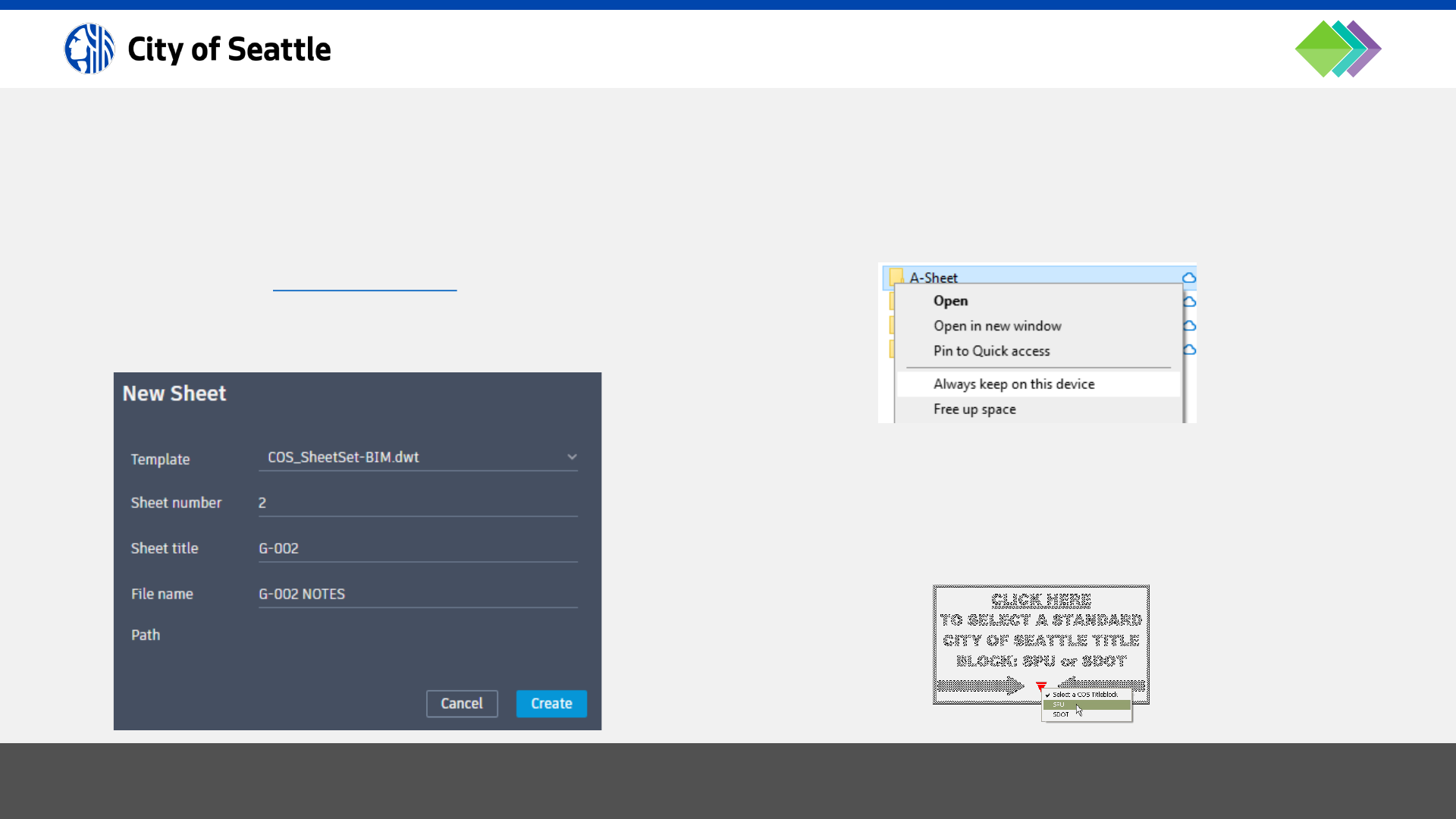
When creating sheets in Sheet Set Manager, it will prompt
the user to enter:
• Sheet Number: the absolute sheet number.
• Sheet Title: the drawing number (discipline).
• File Name: the sheet drawing file name.
3 . 4 . 1 c S D OT / S P U S H E E T S TA N DA R D S ( 3 O F 1 1 )
Once the sheet has been created, in Windows File
Explorer navigate to the A-Sheet folder, right-click, and
select “always keep on this device”.
This will allow the user to open the drawing to make edits.
The title block is dynamic so when the user creates a new
sheet, they can choose which logo appears in it:
/Project Files/A-Sheets

8/30/2024 City of Seattle BIM Standards 51
Click on the Sheet Set heading to view the Custom Sheet
Set Properties:
3 . 4 . 1 d S D OT / S P U S H E E T S TA N DA R D S ( 4 O F 1 1 )
Click on a sheet to edit the description:
The description will appear as the sheet title in the
drawing.
Blank Fields
To clear the contents of a field, enter: %%

8/30/2024 City of Seattle BIM Standards 52
It is important to plan design views to fit inside the SPU/SDOT title block. The total drawing space within the title
block is 32”x19”. The profile grid takes up 30”x9”.
When planning for drawing views, leave about ½ inch space on every side that has a match line and about 1 inch of
space under profile views for station labels. Also, if a legend or notes will appear on the sheet, leave about 5 or 6
inches on the right-hand side.
3 . 4 . 1 e S D OT / S P U S H E E T S TA N D A R D S ( 5 O F 1 1 )

8/30/2024 City of Seattle BIM Standards 53
The title block image shown on the right is a planning tool
to estimate the approximate number of sheets required
for a project.
The scales shown below the title block represent common
viewport scales.
This tool allows the user to plan drawing views using
common engineering and architectural scales. The
drawing area in the image reflects useable drawing area
of the title block. Inside the drawing area is a grid which
contains representations of 1”x1” squares.
A graphic component 100 ft. x 40 ft. drawn at a 1”=20’
scale would be approximated by counting five squares
over and two squares down.
3 . 4 . 1 f S D OT / S P U S H E E T S TA N D A R D S ( 6 O F 1 1 )

8/30/2024 City of Seattle BIM Standards 54
It is crucial to create named views (command: VIEW) in XREF drawings (model space) for planning purposes. View
names must reflect the exact title of the drawing view, detail or section.
For example, an “air valve vault detail” view must be named, AIR VALVE VAULT DETAIL.
The AutoCAD® view manager, however, will not allow certain “special characters” in named views (such as
<>/\’”:;?*|,=`) but there is a workaround. Here are %% codes to use in place of these special characters:
3 . 4 . 1 g S D OT / S P U S H E E T S TA N D A R D S ( 7 O F 1 1 )
%%60 = <
%%62 = >
%%47 = /
%%92 =
\
%%39 = '
%%34 = "
%%58 = :
%%59 = ;
%%44 = ,
%%63 = ?
%%42 = *
%%61 = =

8/30/2024 City of Seattle BIM Standards 55
The sheet index must contain the sheet number (SHT NO = Sheet Number field), drawing number (DWG NO = Sheet
Title field), and description (DESCRIPTION = Sheet Description field). Field names are illustrated in red below:
To create a sheet index, do the following steps:
• Sync the DST file in Desktop Connector.
• Open the sheet that is to contain the sheet index and create a Table as illustrated above with the SHT NO, DWG
NO, and DESCRIPTION headings.
• In each cell, type text or insert a field (right-click and select “Insert Field…” or use CTRL+F) that references the
following data in the standard order:
• SHT NO: “sheet number” field for the sheet
• DWG NO: “sheet title” field for the sheet
• DESCRIPTION: “description” field for the sheet
3 . 4 . 1 h S D OT / S P U S H E E T S TA N D A R D S ( 8 O F 1 1 )
8/30/2024 City of Seattle BIM Standards 56
Sheets must be grouped by discipline code in the order
of the list shown here:
• G: Cover Sheet
• G: Sheet Index (place on cover sheet if less than 55 lines
• G: Notes
• V: Survey Control Plan (including datum info)
• V: Right-of-Way Plan (if needed)
• B: Geotechnical Plans
• C: Site Preparation Plans
• C: CSEC Plans
• C: Demolition/Removal/Protection Plans
(may be combined with CSEC, site, and/or other discipline plans)
• C: Water Plans and Profiles
• C: Water Details
• C: Drainage/Wastewater Plans and Profiles
• C: Drainage/Wastewater Details
• C: Street Lighting and Signal Plans
3 . 4 . 1 i S D OT / S P U S H E E T S TA N D A R D S ( 9 O F 1 1 )
• C: Street Lighting and Signal Details and Diagrams
• C: Power Plans
• C: Power Details and Diagrams
• C: Communications Plans
• C: Communications Details and Diagrams
• C: Paving/Roadway Grading Plans and Profiles
• C: Paving/Roadway Grading Sections and Details
• C: Intersection Plans
• C: Channelization/Signage Plans
• L: Landscaping/Irrigation Plans
• L: Landscaping Details and Schedules
• S: Structural Plans, Details and Sections
• A: Architectural Plans, Elevations, Details and Sections
• M: Mechanical
• E: Electrical Details and Diagrams
• D: P&ID
• X: I&C
• X: Other

8/30/2024 City of Seattle BIM Standards 57
Details must be labeled with a title, scale centered under
the title, reference numbers in a bubble callout to the
right of the title and a North arrow.
Sections must be labeled with a letter designation in this
format: SECTION X-X # (sheet reference is shown to the
right of the title) and scale centered underneath.
Detail and section viewports must be numbered/lettered
via the Sheet Set Manager “Sheet Views” tab and
arranged in order to be read from left-to-right/top-to-
bottom.
There are two types of sections: “civil sections” and “detail
sections”. Civil sections relate to a plan view and are
typically dimensioned in an engineering format while
detail sections relate to a detail view and are dimensioned
in an architectural format.
Reference Boxes
Use layer []-DETL-ANNO-REFR (color yellow, linetype
PHANTOM2) to create a box that references to another
detail or sheet.
3 . 4 . 1 j S D OT / S P U S H E E T S TA N DA R D S ( 1 0 O F 1 1 )

8/30/2024 City of Seattle BIM Standards 58
AutoCAD® Fields can be inserted for Sheet Set Manager view numbers and sheet numbers in Text, MTEXT,
Dimensions, Multileaders and block attributes. To do this, sync the DST file in Desktop Connector, use the CTRL+F
keyboard shortcut or right-click and select “Insert Field…” when in any AutoCAD® text editor, and select the
“SheetSet” field name.
Insert SSM blocks from here: …\W-Support
3 . 4 . 1 k S D OT / S P U S H E E T S TA N D A R D S ( 1 1 O F 1 1 )
DETAIL TITLES: Use either SSM-view_label_standard-DB.dwg,
SSM-view_label_broken-DB.dwg, or SSM-view_label_multiline-DB.dwg for detail
titles. These blocks may be placed under the detail views in paper space. These
blocks must refer to the sheet the detail was taken from. To do this, double-click on
the sheet number to edit the attribute and then double-click on the sheet number
value to assign the correct sheet.
SECTION TITLES: Use SSM-section_view_label.dwg for section titles. This block
may be placed under the section views in paper space and it must refer to the
sheet the section was taken from.
DETAIL REFERENCE CALLOUTS: Use either SSM-callout.dwg or
SSM-callout_broken.dwg next to annotation (such as a multileader, as shown here)
to refer to a detail’s number and the sheet number where it is displayed.
SECTION REFERENCE CALLOUTS: Use SSM-section_arrows-DB.dwg to indicate
where a section is cut and to refer to the section’s letters and the sheet number
where it is displayed.
MATCH LINES: Use the following match line blocks in paper space:
SSM-match_line-L.dwg (left match lines; may also be used for top match lines) or
SSM-match_line-R.dwg (right match lines; may also be used for bottom match
lines).

BIM Standards
8/30/2024 City of Seattle BIM Standards 59
SECTION 4: Drawing Standards

8/30/2024 City of Seattle BIM Standards 60
Every drawing must be in the world UCS with the 0,0 point defined by Survey in the Survey drawing. It is important to
utilize the standard coordinate system in order to allow information from different design disciplines to be displayed
together and be published to GIS. Each design drawing must be in model space (no design elements in paper
space). Have the base and other design drawings externally referenced during editing sessions, and when finished,
detach all XREFs.
• North arrows must be oriented up, to the left or aligned within the area shown on the right.
• Do not draw on layers 0 (zero) or Defpoints because they cannot be manipulated in an XREF.
• Create the design in model space at 1 drawing unit = 1 ft.
• The XREF type must always be “overlay” and the XREF path type must always be “relative path”.
• Draft at Z = 0, design at Z = true elevation, on the correct horizontal and vertical datums.
• Use standard COS layers, colors and linetypes; see layer standards database.
• Abbreviations must be shown in accordance with Standard Plan No. 002.
• Features must be drawn in accordance with Standard Plan No. 003.
• Lettering must not be shown to identify features for which standard symbols are used, unless lettering is shown in
the standard symbols.
• Linetype variables LTSCALE, PSLTSCALE, MSLTSCALE & CELTSCALE must always be set to 1.
4 . 0 D R A W I N G S TA N DA R D S

8/30/2024 City of Seattle BIM Standards 61
Authoritative Drawings
It is important to designate drawings as authoritative, which means drawings that are used for data referencing and for
printing on sheets. Unless otherwise noted in the BIMxp, authoritative drawings must reside in this location:
…\C-Civil\03-Design
Before creating authoritative XREF drawings, create a “Civil Plan Views” drawing (name of drawing file: [PTN]_X-
VIEW.dwg) and in model space add overlapping rectangles (for civil drawings put the rectangles on layer C-VIEW-
FRME) representing the limits of sheet viewports with match lines inside the overlap areas. These rectangles are scaled
by the planned viewport scale factor (for example, a 5”x2” rectangle in paper space equals 100’x40’ in model space at
1”=20’). Then create a named view for each rectangle. To do this, align the UCS (command: UCS) with the rectangle so
the Y direction is aligned along the narrow edge of the rectangle, orient the drawing space to align with the UCS
(command: PLAN; use “current” option) and create a named view (command: VIEW) that matches the limits of the box.
Repeat this for every rectangle. When finished, set the UCS back to World and copy and rename the drawing file as a
starting point to create every other authoritative plan XREF.
Work in Progress (WIP) Drawings
Working drawings may be created but must be saved separate from the authoritative drawings. Unless otherwise noted
in the BIMxp, working drawings must reside in this location:
…\C-Civil\03-Design\[team folder]\WIP
4 . 0 . 1 a C I V I L I N F O R M AT I O N M O D E L D R A W I N G S TA N DA R D S ( 1 O F 3 )

8/30/2024 City of Seattle BIM Standards 62
Survey: [PTN]_3D-TOPO-[optional_description].dwg
Right-of-Way: [PTN]_2D-RWAY-[optional_description].dwg
Base Map: [PTN]_3D-BASE-[optional_description].dwg
Site Preparation: [PTN]_2D-SITE-[optional_description].dwg
CSEC: [PTN]_2D-EROS-[optional_description].dwg
Removal: [PTN]_2D-DEMO-[optional_description].dwg
Protection: [PTN]_2D-PROT-[optional_description].dwg
Water: [PTN]_3D-WATR-[optional_description].dwg
Drainage: [PTN]_3D-STRM-[optional_description].dwg
Sewer: [PTN]_3D-SSWR-[optional_description].dwg
Combined Sewer: [PTN]_3D-CSWR-[optional_description].dwg
Architectural: [PTN]_3D-ARCH-[optional_description].dwg
Structural: [PTN]_3D-STRU-[optional_description].dwg
Mechanical: [PTN]_3D-MECH-[optional_description].dwg
4 . 0 . 1 b C I V I L I N F O R M AT I O N M O D E L D R A W I N G S TA N DA R D S ( 2 O F 3 )
Pond: [PTN]_3D-POND-[optional_description].dwg
Grading: [PTN]_3D-GRAD-[optional_description].dwg
Paving: [PTN]_2D-PVMT-[optional_description].dwg
Roadways: [PTN]_2D-ROAD-[optional_description].dwg
Accessibility Ramps: [PTN]_2D-RAMP-[optional_description].dwg
Channelization: [PTN]_2D-MRKG-[optional_description].dwg
Traffic Signals: [PTN]_2D-SIGL-[optional_description].dwg
Lighting: [PTN]_2D-LITE-[optional_description].dwg
Power/Electrical: [PTN]_2D-POWR-[optional_description].dwg
River and Creek: [PTN]_3D-RIVR-[optional_description].dwg
Landscaping: [PTN]_2D-VEGE-[optional_description].dwg
Irrigation: [PTN]_3D-IRRG-[optional_description].dwg
Details: [PTN]_2D-DETL-[optional_description].dwg
Miscellaneous: [PTN]_2D-MISC-[optional_description].dwg
Here is the standard file-naming convention for authoritative drawings (common examples shown below):
[PTN]_[“2D” or “3D”]-[major layer discipline code]-[optional_description]
BASE
SITE
UTILITIES
SURFACES
FACILITIES
TRANSPORTATION
OTHER

8/30/2024 City of Seattle BIM Standards 63
Civil Drawing Properties
At the 60% milestone and beyond, each model drawing must have the VPI and PTN saved in the Custom Drawing
Properties (command: DWGPROPS), as defined in the BIM Execution Plan (BIMxp).
4 . 0 . 1 c C I V I L I N F O R M AT I O N M O D E L D R A W I N G S TA N D A R D S ( 3 O F 3 )

8/30/2024 City of Seattle BIM Standards 64
Civil 3D® Object Naming Convention
It is important to add understandable names and descriptions to Civil 3D® objects. Some object types may be “data
referenced” into other drawings so it is important to use layer-control to ensure duplicate objects are not visible when
XREFs are overlaid in sheet drawings. Use this format:
[major layer discipline code]-[optional location]-[optional description]
Example for Pipe Network Names
Sanitary Sewer: SSWR-[optional location]-[optional description]
Storm: STRM-[optional location]-[optional description]
Combined Sewer: CSWR-[optional location]-[optional description]
Example for Pressure Network Names
Water: WATR-[optional location]-[optional description]
Gas: NGAS-[optional location]-[optional description]
4 . 0 . 2 a C I V I L I N F O R M AT I O N M O D E L O B J E C T S TA N D A R D S ( 1 O F 2 )

8/30/2024 City of Seattle BIM Standards 65
Custom Civil 3D® Object Properties
Select a Civil 3D® object, run the Properties command,
and go to the “Extended Data” tab to enter custom data.
SUE Quality Levels
Set the quality level by selecting the QL dropdown.
QL-A: direct physical observation recorded by survey.
QL-B: indirect physical observation recorded by survey.
QL-C: interpolated based on known survey points.
QL-D: drawn based on records or as proposed data.
Sheet References
Add sheet references by right-clicking in the Sheet field
and selecting, “Insert Field…” (you may enter a single
sheet such as 5, more than one sheet separated by
commas such as 5,9 or a range of sheets such as 5-7).
4 . 0 . 2 b C I V I L I N F O R M AT I O N M O D E L O B J E C T S TA N DA R D S ( 2 O F 2 )

8/30/2024 City of Seattle BIM Standards 66
All drawings must conform to the City of Seattle Standard Specifications and Plans for Municipal Construction.
Standard plans may be referenced in the plan set (such as, “SEE STANDARD PLAN 422A”), but any modifications of
the standard plans must be approved by the project engineer and illustrated as a detail in the plan set.
Civil 3D® templates and catalogs have been provided to create designs that meet the Standard Specifications and
Plans, including linetypes, pipes, structures, appurtenances, fittings, and symbols (blocks/Cogo points).
Any modifications to the Pipe or Pressure Network catalogs must be documented in the BIMxp and shared with the
project team.
4 . 0 . 3 a C I V I L H O R I Z O N TA L A S S E T S TA N D A R D S ( 1 O F 1 4 )

8/30/2024 City of Seattle BIM Standards 67
Base Maps
Template (new drawing): COS-SV-Blank.dwt
Attached reference template: COS-SV-Master.dwt
Pipe Network catalog: Gravity
Pipe Network parts lists: RU-STRM, RU-SSWR, RU-CSWR
(per Standard Plan 003 & 200)
Utility/paving/topo lines: Feature Lines
Symbols per Standard Plan 003: Description Key Sets
4 . 0 . 3 b C I V I L H O R I ZO N TA L A S S E T S TA N D A R D S ( 2 O F 1 4 )
Jump back to template list…

8/30/2024 City of Seattle BIM Standards 68
Drainage and Wastewater (DWW) Design
Template (new drawing): COS-New-DD.dwt
Attached reference template: COS-DD-Ref-00-General.dwg + COS-DD-Ref-CU-DWW.dwg
Pipe Network catalog: Gravity
Pipe Network parts lists: CU-STRM, CU-SSWR, CU-CSWR
(per Standard Plan 003 & 200)
Structure label styles: CU-STRC-PLAN, CU-STRC-PLAN-PIPE
Pipe label styles: C-LOOP-LRGE (double line pipes), C-LOOP-SMAL (single line pipes)
4 . 0 . 3 c C I V I L H O R I ZO N TA L A S S E T S TA N D A R D S ( 3 O F 1 4 )
Jump back to template list…

8/30/2024 City of Seattle BIM Standards 69
Grading Design
Template (new drawing): COS-New-DD.dwt
Attached reference template: COS-DD-Ref-00-General.dwg + COS-DD-Ref-CG-GRAD.dwg
Site(s): Create sites as needed for design.
Top/bottom of pond/swale: Feature Lines
Grading breaklines: Feature Lines
4 . 0 . 3 d C I V I L H O R I ZO N TA L A S S E T S TA N D A R D S ( 4 O F 1 4 )
Jump back to template list…

8/30/2024 City of Seattle BIM Standards 70
Water Systems Design
Template (new drawing): COS-New-DD.dwt
Attached reference template: COS-DD-Ref-00-General.dwg + COS-DD-Ref-CU-WATR.dwg
Pressure Network catalog:* Pressure
Pressure Network parts lists:* CU-WATR-DIP, CU-WATR-MJ
Site(s): Create sites as needed for design.
Water lines: Feature Lines
Water symbols: Description Key Set: “COS Design Pressure”
(per Standard Plan 003 & 300) (use the CreatePointManual command to insert symbols; for a list of symbol
codes, go to Toolspace → Settings → Point → Description Key Sets and
right-click on the Description Key Set shown above to view the list of
available codes)
*optional for design and clash detection
4 . 0 . 3 e C I V I L H O R I ZO N TA L A S S E T S TA N D A R D S ( 5 O F 1 4 )
Jump back to template list…

8/30/2024 City of Seattle BIM Standards 71
Roadway Paving Design
Template (new drawing): COS-New-DD.dwt
Attached reference template: COS-DD-Ref-00-General.dwg + COS-DD-Ref-CP-ROAD.dwg
Site(s): Create sites as needed for design.
Paving edge lines: Feature Lines
4 . 0 . 3 f C I V I L H O R I ZO N TA L A S S E T S TA N D A R D S ( 6 O F 1 4 )
Jump back to template list…

8/30/2024 City of Seattle BIM Standards 72
Roadway Channelization Design
Template (new drawing): COS-New-DD.dwt
Attached reference template: COS-DD-Ref-00-General.dwg + COS-DD-Ref-CP-CHAN.dwg
Channelization lines: Polylines
Channelization symbols: Blocks
(per Standard Plan 003)
4 . 0 . 3 g C I V I L H O R I ZO N TA L A S S E T S TA N D A R D S ( 7 O F 1 4 )
Jump back to template list…

8/30/2024 City of Seattle BIM Standards 73
Curb Ramp Design
NOTE: curb return curves must be created with Arc objects to extract geometry data (see Civil 3D® plugins).
Template (new drawing): COS-New-DD.dwt
Attached reference template: COS-DD-Ref-00-General.dwg + COS-DD-Ref-CP-CURB.dwg
Site: Create an “ADA” site with Feature Line style hierarchy shown below.
Curb and ramp breaklines: Feature Lines
Line and curve labels: Use AddFeatureLineLabels command to add “Line and Curve” labels.
4 . 0 . 3 h C I V I L H O R I ZO N TA L A S S E T S TA N DA R D S ( 8 O F 1 4 )
FEATURE LINE STYLE HEIRARCHY
LAYER
COLOR
LINETYPE
ADA RAMP
CP
-SWLK-RAMP-MINR
GREEN
CONTINUOUS
ADA RAMP WINGS
CP
-SWLK-RAMP-MAJR
YELLOW
CONTINUOUS
ADA LANDING
CP
-SWLK-RAMP-LEVL
YELLOW
GRID1
ADA BREAKLINE
CP
-SWLK-GRAD-BRKL
22
HIDDEN2
ADA CURB BACK
CP
-ROAD-CURB-BACK
CYAN
CONTINUOUS
ADA CURB FACE
CP
-ROAD-CURB-FACE
CYAN
CONTINUOUS
ADA CONCRETE
CP
-SWLK-CONC-OTLN
YELLOW
CONTINUOUS
ADA FLOWLINE
CP
-ROAD-CURB-FEAT
CYAN
CONTINUOUS
ADA DRIVEWAY
CP
-SWLK-GRAD-BRKL
22
HIDDEN2
Jump back to template list…

8/30/2024 City of Seattle BIM Standards 74
Roadway Signalization Design
Template (new drawing): COS-New-DD.dwt
Attached reference template: COS-DD-Ref-00-General.dwg + COS-DD-Ref-CT-SIGL.dwg
Site(s): Create sites as needed for design.
Signalization lines: Feature Lines
Signalization symbols per Standard Plan 003: Description Key Set: “COS Design Signalization”
(use the CreatePointManual command to insert symbols; for a list of
symbol codes, go to Toolspace → Settings → Point → Description
Key Sets and right-click on the Description Key Set shown above to
view the list of available codes)
4 . 0 . 3 i C I V I L H O R I ZO N TA L A S S E T S TA N D A R D S ( 9 O F 1 4 )
Jump back to template list…
8/30/2024 City of Seattle BIM Standards 75
Electrical Site Design
Template (new drawing): COS-New-DD.dwt
Attached reference template: COS-DD-Ref-00-General.dwg + COS-DD-Ref-CS-ELEC.dwg
Site(s): Create sites as needed for design.
Electrical lines: Feature Lines
Electrical symbols per Standard Plan 003: Description Key Set: “COS Design Electrical”
(use the CreatePointManual command to insert symbols; for a list of
symbol codes, go to Toolspace → Settings → Point → Description
Key Sets and right-click on the Description Key Set shown above to
view the list of available codes)
4 . 0 . 3 j C I V I L H O R I Z O N TA L A S S E T S TA N D A R D S ( 1 0 O F 1 4 )
Jump back to template list…

8/30/2024 City of Seattle BIM Standards 76
Lighting Site Design
Template (new drawing): COS-New-DD.dwt
Attached reference template: COS-DD-Ref-00-General.dwg + COS-DD-Ref-CS-LITE.dwg
Site(s): Create sites as needed for design.
Lighting lines: Feature Lines
Lighting symbols per Standard Plan 003: Description Key Set: “COS Design Lighting”
(use the CreatePointManual command to insert symbols; for a list of
symbol codes, go to Toolspace → Settings → Point → Description
Key Sets and right-click on the Description Key Set shown above to
view the list of available codes)
4 . 0 . 3 k C I V I L H O R I ZO N TA L A S S E T S TA N D A R D S ( 1 1 O F 1 4 )
Jump back to template list…

8/30/2024 City of Seattle BIM Standards 77
Roadway Signage Design
Template (new drawing): COS-New-DD.dwt
Attached reference template: COS-DD-Ref-00-General.dwg + COS-DD-Ref-CT-SIGN.dwg
Signage symbols per Standard Plan 003: Description Key Set: “COS Design Signage”
(use the CreatePointManual command to insert symbols; for a list of
symbol codes, go to Toolspace → Settings → Point → Description
Key Sets and right-click on the Description Key Set shown above to
view the list of available codes)
4 . 0 . 3 l C I V I L H O R I Z O N TA L A S S E T S TA N D A R D S ( 1 2 O F 1 4 )
Jump back to template list…

8/30/2024 City of Seattle BIM Standards 78
Tree Planting Design
Template (new drawing): COS-New-DD.dwt
Attached reference template: COS-DD-Ref-00-General.dwg + COS-DD-Ref-LP-TREE.dwg
Tree symbols per Standard Plan 003: Description Key Set: “COS Design Trees”
(use the CreatePointManual command to insert symbols; for a list of symbol
codes, go to Toolspace → Settings → Point → Description Key Sets and right-
click on the Description Key Set shown above to view the list of available
codes)
4 . 0 . 3 m C I V I L H O R I ZO N TA L A S S E T S TA N DA R D S ( 1 3 O F 1 4 )
Jump back to template list…

8/30/2024 City of Seattle BIM Standards 79
Irrigation Systems Design
Template (new drawing): COS-New-DD.dwt
Attached reference template: COS-DD-Ref-00-General.dwg + COS-DD-Ref-LI-IRRG.dwg
Site(s): Create sites as needed for design.
Irrigation lines: Feature Lines
Irrigation symbols per Standard Plan 003: Description Key Set: “COS Design Irrigation”
(use the CreatePointManual command to insert symbols; for a list of
symbol codes, go to Toolspace → Settings → Point → Description
Key Sets and right-click on the Description Key Set shown above to
view the list of available codes)
4 . 0 . 3 n C I V I L H O R I Z O N TA L A S S E T S TA N D A R D S ( 1 4 O F 1 4 )
Jump back to template list…

8/30/2024 City of Seattle BIM Standards 80
External Referencing, or XREF’ing, is the standard procedure for concurrent engineering.
All XREFs must be set to OVERLAY and RELATIVE in sheet drawings and overlaid in the correct order so the base map
is on the bottom and the primary XREF is on the top. To avoid duplicate contours and alignments, freeze base map
and secondary XREF contours and alignments if those objects are shown in the primary XREF.
If information is not visible through a viewport, make model space of the viewport active, open Layer Manager, check
the “VP Freeze” column for frozen layers and thaw them if necessary. After doing this, if linework appears but
annotation is still invisible, set ANNOALLVISIBLE to 1 to see annotation not associated with the viewport scale.
4 . 0 . 4 a E X T E R N A L R E F E R E N C I N G S TA N D A R D S ( 1 O F 2 )

8/30/2024 City of Seattle BIM Standards 81
Every design discipline must be a separate XREF drawing (drawings are more efficient if they only contain objects of a
single discipline). It is the standard to publish each discipline to ArcGIS separately (see Section 5.3) at milestones
specified in the BIMxp and keeping disciplines in separate drawings makes this process easier.
To create the highest-quality deliverables, these requirements must be followed:
1. The base map drawing must be XREF’d into design drawings as a basis for the design from this location:
…\C-Civil\02-Survey\D-XREF (do not make copies of the base map).
2. Do not insert unnecessary items (things that won’t be printed, referenced, or published) into drawings.
3. Use the Autodesk Batch Save Utility (Standalone) to keep drawings clean by running cleanup scripts
(see: …\W-Support\COS-defaultClean.lsp) to purge registered apps and run audits to fix errors. This will reduce
errors showing up in referenced drawings.
4. BIM is a cloud-only system thus you must not XREF drawings from local or network locations (otherwise a “related
data” folder will appear in the cloud). Before referencing a drawing, save it to the cloud first, and then create the
external reference.
5. Work in progress files must be saved in a WIP subfolder and not referenced into any standard drawings.
6. Sheet drawings (paper-space layouts) must reference the base map and design drawings into model-space, and
display all or a portion of the composite plan view with viewports in sheet drawings. Overlay the primary XREF last
so it is on top of all other XREFs (to put the primary XREF back on top, use the COPYBASE command with a base
point of 0,0,0 and erase the XREF; then use the PASTECLIP command with the insertion point 0,0,0).
4 . 0 . 4 b E X T E R N A L R E F E R E N C I N G S TA N DA R D S ( 2 O F 2 )

8/30/2024 City of Seattle BIM Standards 82
Setup the cover sheet and place the sheet index. The sheet index may need to go on another sheet if the plan set
contains more than 55 sheets. The cover sheet must contain:
• Vicinity map at scale: 1” = 1 MILE
• Location map (may go on another sheet if more room is required) at scale: 1” = 400’
• Datum block
• Vertical datum note:
• Benchmark reference number, description (including location), and elevation
• Datum name
• Horizontal datum note:
• Basis of bearing description
• Description of monuments used for basis of bearing
• Coordinates on each monument used for basis of bearing
• Bearing and distance between the two monuments
• Source of coordinates (published, GPS, or what?)
• Detail & section referencing block
• Sheet index table (may go on another sheet if more room is required)
• Notes (may go on another sheet if more room is required)
4 . 0 . 5 C O V E R S H E E T S TA N D A R D S

8/30/2024 City of Seattle BIM Standards 83
Survey control information must be included in every plan set. The survey control information may be included on the
location map or may be shown on its own sheet. The survey control information sheet must meet SIP requirements,
including these basic items:
• Street names.
• Description of every monument (cased, buried, surface brass cap, etc.).
• Coordinates for each monument, which must include Northing and Easting.
• Bearing and distance on each street between each two monuments, and distance from offset monument (if any) to
intersection.
• Radius, delta angle, and arc length on any curving monument lines or baselines.
• Bearing and distance and/or dimension from monumented line to construction baselines (if any).
• Stations at intersections and all monuments.
• Station numbering must be unique for each street. Come up with different starting stations for each street
alignment so that the numbers do not overlap (start with 10+00 and go up from there).
• Survey alignments must be labeled with 100-foot tics.
4 . 0 . 6 a S U R V E Y C O N T R O L S H E E T S TA N D A R D S ( 1 O F 2 )

8/30/2024 City of Seattle BIM Standards 84
• Stationing on North/South alignments must increase to the South to abide by city presentation standard of north
up or left. Stationing on East/West alignments must increase to the East to abide by city presentation standard of
north up or left.
• Station at the beginning, end, at each intersection and at PCs and PTs of curving monument lines (no stationing
that starts at property line, end of existing paving, or other indeterminate point).
• Description and elevation of any site BMs or control points with elevation (it is ok to use monuments with
elevations as site BMs).
• Dimension from monument line to right-of-way line on each street; if variable, show dimension at each end of
block.
• Washington State Licensed surveyor’s stamp (stamp must be signed if plans are complete).
• Current contact information for the surveyor whose stamp appears on the drawing (name, address, phone, and/or
email).
4 . 0 . 6 b S U R V E Y C O N T R O L S H E E T S TA N D A R D S ( 2 O F 2 )

8/30/2024 City of Seattle BIM Standards 85
Proposed alignments must reside in the XREF drawing they are associated with (for example, a water main alignment
must be created in the X-WATR drawing) and be labeled with 100-foot tics.
All stationing callouts in profiles must reference the project control alignment (usually the surveyed roadway
centerline). Some Profiles may be created for presentation purposes (shown on sheets) while some may be created
for reference or design purposes but not shown on the sheets.
Profile Views (grids) in model space are for reference only and are used to align with the grids provided in layouts of
sheet drawings through viewports (Profile View layers are set to not print).
4 . 0 . 7 a P L A N A N D P R O F I L E S H E E T S TA N DA R D S ( 1 O F 1 0 )

8/30/2024 City of Seattle BIM Standards 86
Profile views are typically shown above plan views on
utility sheets and shown under plan views for roadway
sheets. The plan and profile views must be aligned so that
the improvement is in direct relationship between the two
views as much as possible.
Plan views must show callouts containing horizontal
information (such as stations and offsets), including
vertical information only if it is not represented in a profile
view.
Profiles must show callouts containing vertical information
(such as invert and rim elevations), including horizontal
information only if it cannot be represented in a plan view.
4 . 0 . 7 b P L A N A N D P R O F I L E S H E E T S TA N DA R D S ( 2 O F 1 0 )
All disciplines (paving plans, watermain plans, sewer
plans, etc.) must use the same match line locations.
Street names must be shown.
Plan views must have a North arrow with a bar scale under
it.
For multi-discipline projects, show nearby improvements
for context (such as showing water improvements on a
drainage plan) but freeze the annotation and change the
linework to color 145. To do this, overlay an XREF of the
secondary improvement, viewport freeze (VP Freeze)
secondary improvement layers that don’t need to be
shown (such as annotation) and change the viewport color
(VP Color) of the remaining secondary improvement
layers to color 145.
Proposed geo-referenced features and vertices of area
limits must be labeled in such a way as to easily locate in
the field (such as station/offset labels, Northing/Easting
labels or point labels referring to a table containing
station/offset data).

8/30/2024 City of Seattle BIM Standards 87
Match Lines
Adjoining sheets must use match lines at an even station
with the sheet number referenced.
Dimensioning between features shown on separate
sheets must be shown with double arrow-heads at the
match line.
The scale must not change across match lines.
Match lines may not be placed in intersections.
4 . 0 . 7 c P L A N A N D P R O F I L E S H E E T S TA N DA R D S ( 3 O F 1 0 )
Construction Stormwater Erosion Control (CSEC) Plans
Soil, vegetation, and tree protection shown; use an
existing lineweight (color 125) and a proposed callout
stating that the item is to be protected.
A legend must be included on CSEC sheets for linetypes,
symbols, and hatch patterns used.
Site Prep and Removal/Demolition Plans
Show clearing and grubbing, utility relocations, building
removal and other items being removed that are not
covered elsewhere in the plan set.
Items to be removed must be shown in bold, crossed out
or covered with a hatch pattern.
All other removal items must be shown on the sheets they
are associated with in an existing lineweight (color 125)
with a proposed (bold) callout.

8/30/2024 City of Seattle BIM Standards 88
Utility Plans
• Leader callout showing the identification of each structure (during the design phase, use name/number in this
format: MH-#, VAULT-#, CB-#, INL-#, etc.; ultimately maintenance holes must have the endpoint identification
number as determined by the project team) above the “type” as defined in the City of Seattle Standard Plans and
the station and offset from a monument line or construction baseline to:
• center of structures (maintenance holes, cleanouts, hydrants, valves, etc.), except most catch basins and
inlets are stationed at the face of curb.
• all horizontal break points and all connection points.
NOTE: if a structure is not shown in a profile, also include the rim elevation and invert elevation(s)
with compass direction(s) in parenthesis.
4 . 0 . 7 d P L A N A N D P R O F I L E S H E E T S TA N D A R D S ( 4 O F 1 0 )

8/30/2024 City of Seattle BIM Standards 89
Utility Plans (continued)
• Each pipe run (between structures or maintenance holes) must have a loop-leader callout showing the size, type of
pipe and material in parenthesis.
• Double-line pipes shown in plan views are filled with hatch while maintenance holes and structures are not.
4 . 0 . 7 e P L A N A N D P R O F I L E S H E E T S TA N DA R D S ( 5 O F 1 0 )

8/30/2024 City of Seattle BIM Standards 90
Utility Profiles
• Horizontal scale must match associated plan view scale. Vertical scales may vary.
• Pipes are projected onto the profile view(s) aligned with existing street control stationing as a general rule
(exceptions: pipes in non-roadway sites such a parking lots, parks or hillsides may need to be shown as true-length
for clarity).
• Profiles are required for all sewer, storm drain, combined sewer and water mains and must include:
• Each gravity pipe run must have a horizontal dimension line below that goes from center of MH to center
of MH showing the length (linear feet), size (inches), type, material in parenthesis, and slope (percentage).
For example: 60 LF 12”PS (DIP) AT 2.00% SLOPE. Other pipes connected to drainage structures are
dimensioned from the inside face of structure walls.
4 . 0 . 7 f P L A N A N D P R O F I L E S H E E T S TA N D A R D S ( 6 O F 1 0 )

8/30/2024 City of Seattle BIM Standards 91
Utility Profiles (continued)
• …and must include:
• Vertical callout above each structure showing the structure’s identification (name/number) on the left side
and rim elevation on the right side (in this format: RIM ##.#’). Station and offset callouts are not required in
utility profiles unless not shown anywhere else.
• Vertical callout below structures and pipes showing elevations at each invert, connection, and/or grade
break on each pipe (in this format: IE ##.##’).
• Each water pipe run must have a horizontal dimension line below showing the length (linear feet), size
(inches), type (W), material in parenthesis, class of bedding and type of protection. For example: 60 LF
12”W (DIP), CLASS B SAND BEDDING, JOINT BONDING & POLYWRAP.
• Radius and delta angle of curved pipes, if applicable.
• Double-line pipes shown in profile views are filled with hatch while maintenance holes and structures are
not.
4 . 0 . 7 g P L A N A N D P R O F I L E S H E E T S TA N D A R D S ( 7 O F 1 0 )
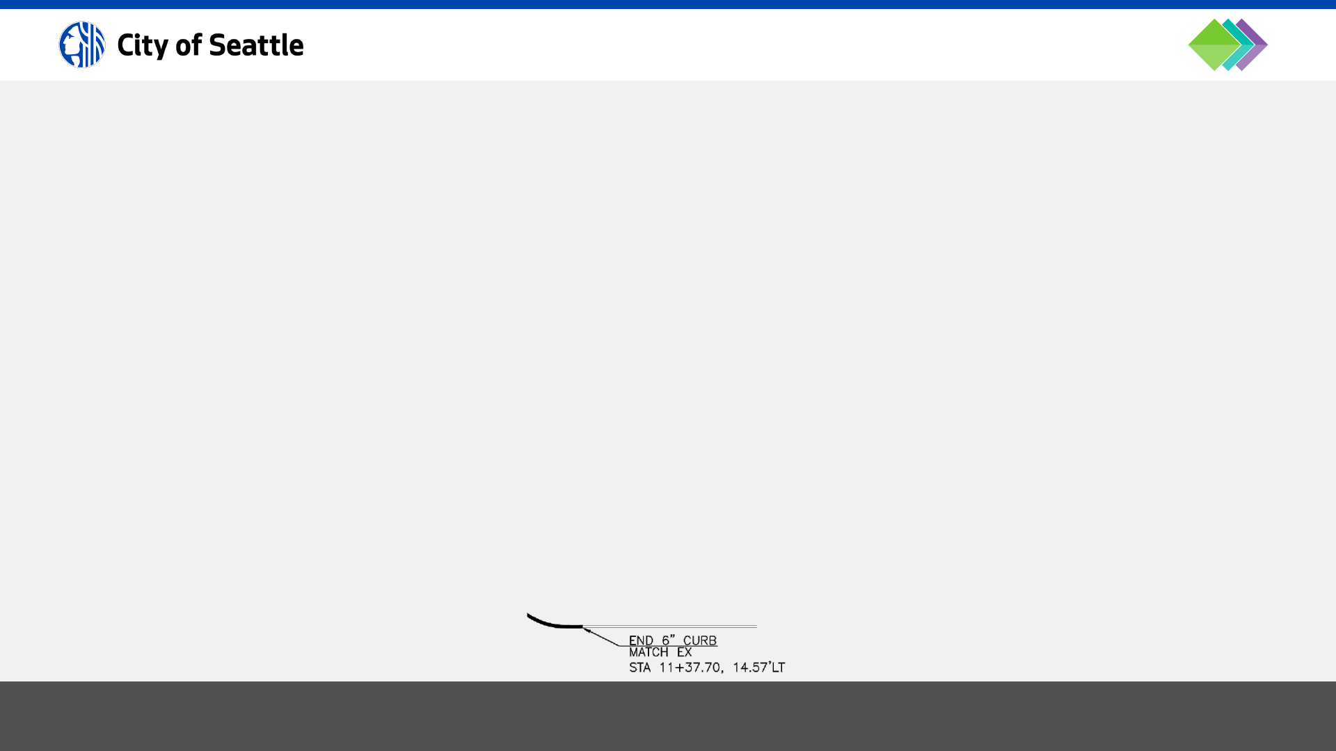
8/30/2024 City of Seattle BIM Standards 92
Paving Plans
Show outlines of castings/openings in paved area.
Spot elevations are shown at least every 25 feet at the crown, flow line, top of curb and property line with the
following descriptions (may be shown in a point table):
CROWN
EDGE OF PAVEMENT
FLOW LINE
BACK OF WALK
FRONT OF WALK
GROUND LINE
GRADE BREAK LINE
Station and offset (or station and pavement width) from monument line or construction baseline to all beginnings and
ends of curb and/or “match existing” points, angle points, and changes of curb height.
4 . 0 . 7 h P L A N A N D P R O F I L E S H E E T S TA N DA R D S ( 8 O F 1 0 )
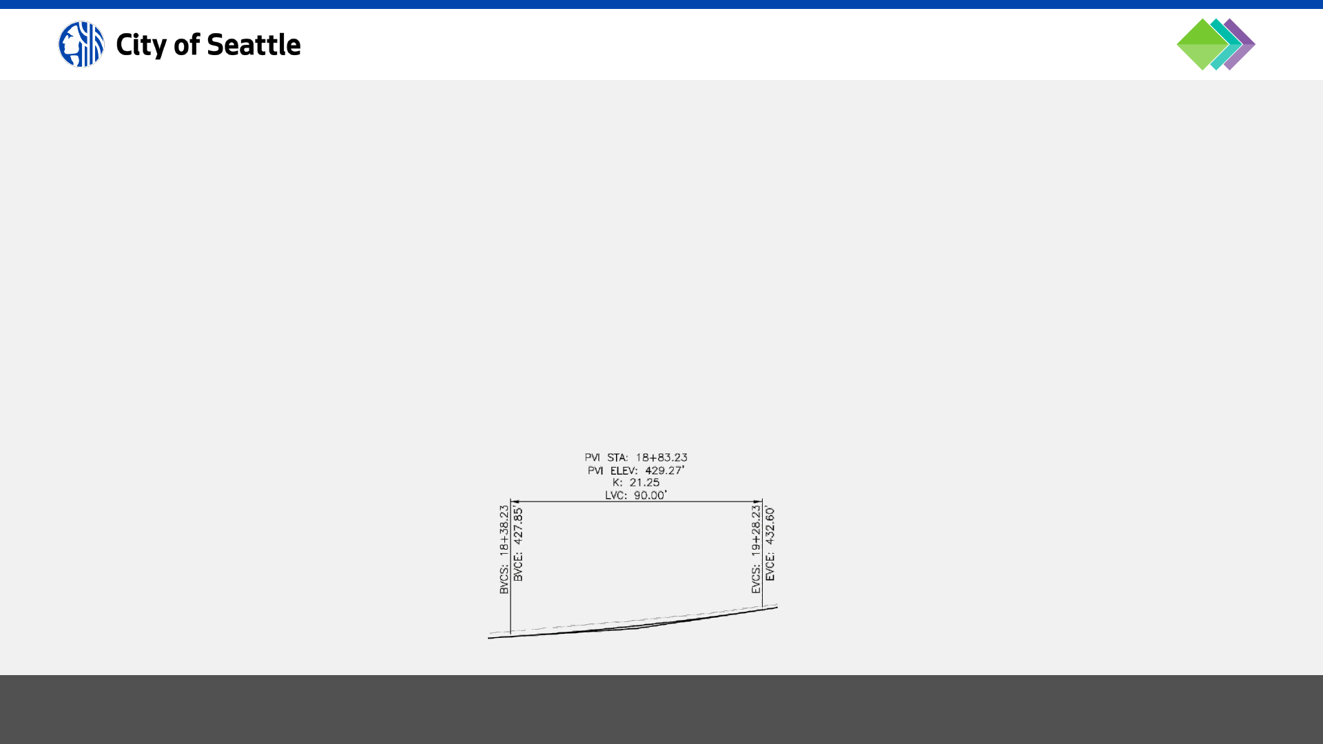
8/30/2024 City of Seattle BIM Standards 93
Paving Profiles
• Call out whether the profile refers to the centerline of road, top of curb, gutter/flow line, or other feature.
• Show elevations and stations at all grade breaks.
• Show elevations at all “match existing” points.
• Provide a description of any vertical curves (required for grade changes greater than 1%). The description must
include:
• VPI station and elevation.
• Length of vertical curve (min along streets is 75’).
• High or low point station and elevation, if applicable.
4 . 0 . 7 i P L A N A N D P R O F I L E S H E E T S TA N DA R D S ( 9 O F 1 0 )

8/30/2024 City of Seattle BIM Standards 94
Paving Cross Sections
• Dimension from centerline to saw cut, flow line (if other than base of curb), face of curb, sidewalk and sidewalk
width, and right-of-way line.
• Show height of curb or dimensions of thickened edge of asphalt.
• Show cross slope on all paved surfaces.
4 . 0 . 7 j P L A N A N D P R O F I L E S H E E T S TA N DA R D S ( 1 0 O F 1 0 )

8/30/2024 City of Seattle BIM Standards 95
Intersection geometry must be shown on dedicated sheets at 1”=5’ scale (show street names; match lines are not
required).
Depict curb returns and accessibility ramps per the following:
• Ramp plan views and associated tables must be shown together (through viewports) on the same sheet.
• Number the ramps (clockwise order on the sheets) in rounded rectangle labels that also include the station, offset
and the shortest-side-corner of ramps at the flowline. This is the starting point, and slopes and distances are used
to build the ramp from here.
Use a decimal point to separate the intersection number from the ramp number, for example: 35.4 means, the
fourth ramp at the thirty-fifth intersection.
4 . 0 . 8 a I N T E R S E C T I O N P L A N S H E E T S TA N D A R D S ( 1 O F 7 )

8/30/2024 City of Seattle BIM Standards 96
• Insert the C-CURB block (curb return number in double circles) near the curb arc.
• Underground utility annotation on the base map must be frozen.
• For clarity, freeze any existing ramps shown on the base map.
• Site restoration hatch patterns must not be shown.
• Label accessibility ramp slopes with slope arrows (pointing downstream) to indicate the direction of the slope. Use
distance & slope in a dimension, where required.
• Make sure roadway/centerline stationing is shown.
4 . 0 . 8 b I N T E R S E C T I O N P L A N S H E E T S TA N D A R D S ( 2 O F 7 )

8/30/2024 City of Seattle BIM Standards 97
• Add ramp notes (varies by type) to each intersection sheet containing curb ramps.
• Add legend for grade breaks and landings.
• Add a “MEF” (maximum extent feasible) table for each ramp, per SDOT requirements, along with a list of the
codes:
4 . 0 . 8 c I N T E R S E C T I O N P L A N S H E E T S TA N D A R D S ( 3 O F 7 )

8/30/2024 City of Seattle BIM Standards 98
• Delta angle, radius, tangent and length on all curb returns and reverse curves, elevations at PC’s, PT’s, PRC’s, PCC’s,
quarter points, and high and low points of curb returns (along flowline).
• Elevations of paving surrounding accessibility ramps shall be shown as spot elevations on the plan.
4 . 0 . 8 d I N T E R S E C T I O N P L A N S H E E T S TA N D A R D S ( 4 O F 7 )
Example curb return plan view for illustration-purposes only.

4 . 0 . 8 e I N T E R S E C T I O N P L A N S H E E T S TA N D A R D S ( 5 O F 7 )
99
30% Example: linework drawn.
8/30/2024 City of Seattle BIM Standards
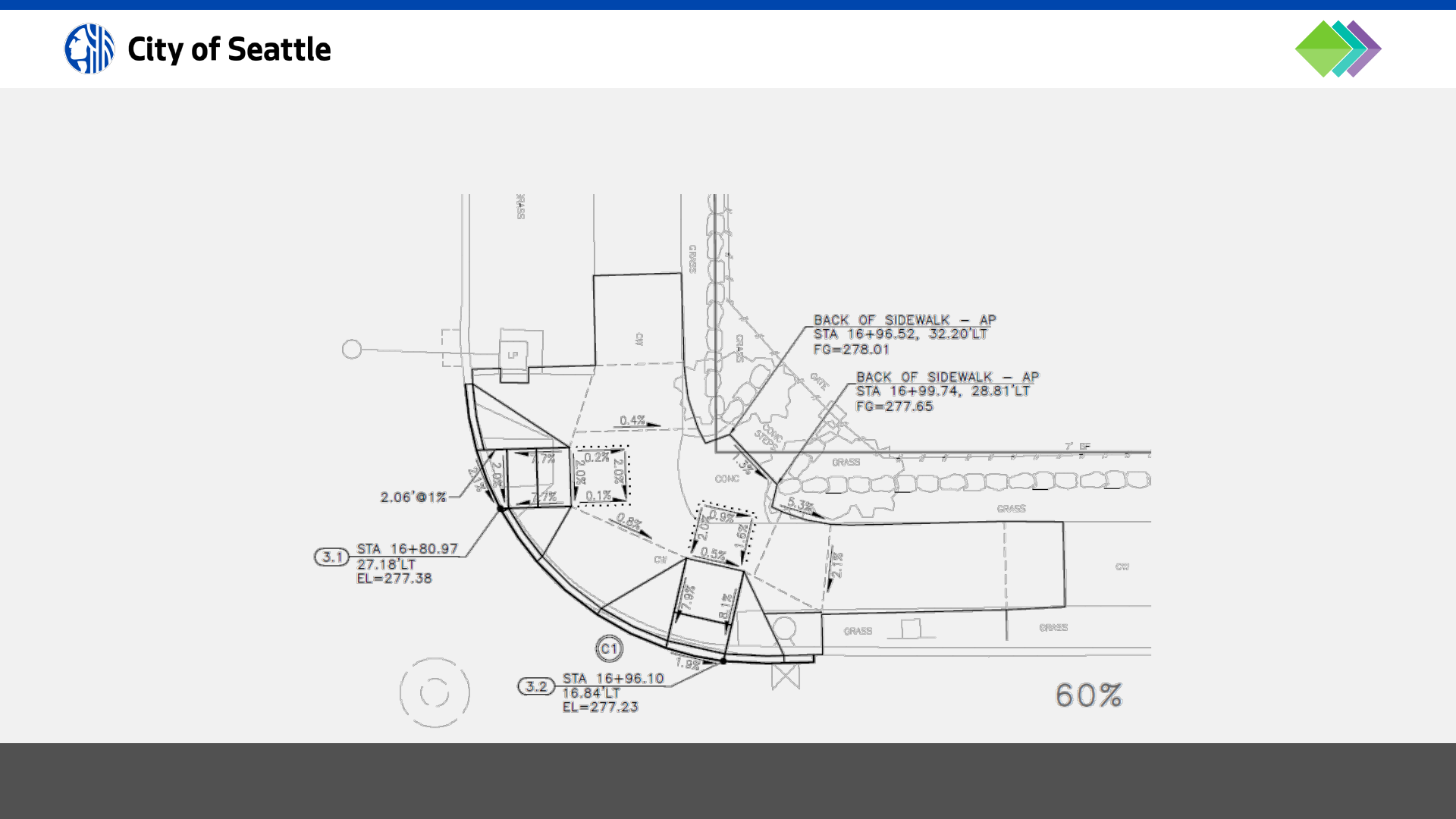
4 . 0 . 8 f I N T E R S E C T I O N P L A N S H E E T S TA N D A R D S ( 6 O F 7 )
100
60% Example: add annotation for the ramp, curb return, back of sidewalk, and some slopes.
8/30/2024 City of Seattle BIM Standards

4 . 0 . 8 g I N T E R S E C T I O N P L A N S H E E T S TA N D A R D S ( 7 O F 7 )
101
90% Example: add dimensions and additional annotation to meet the requirements.
8/30/2024 City of Seattle BIM Standards

8/30/2024 City of Seattle BIM Standards 102
• Add detail and section viewports to sheets via the Sheet Set Manager “Model Views” tab.
• Details must be drawn to scale and are typically dimensioned in an architectural format.
• Details must be separated into individual drawings (XREFs) by discipline. A detail drawing (XREF) must only
contain a set of detail views that share the same scale (unless a detail contains a blow-up).
• There are two types of sections: “civil sections” and “detail sections”. Civil sections relate to a plan view and are
typically dimensioned in an engineering format while detail sections relate to a detail view and are dimensioned in
an architectural format.
• Details must be labeled with a title, scale centered under the title, reference numbers in a bubble callout to the
right of the title and a North arrow.
• Sections must be labeled with a letter designation in this format: SECTION X-X # (sheet reference is shown to the
right of the title) and scale centered underneath.
• Detail and section viewports must be numbered/lettered and arranged in order to be read from left-to-right/top-
to-bottom.
• If a detail is provided in the City of Seattle Standard Plans, simply refer to it by number (e.g. STANDARD PLAN NO
###X); it is not required to be in the plan set unless it is modified.
4 . 0 . 9 D E TA I L S H E E T S TA N D A R D S

8/30/2024 City of Seattle BIM Standards 103
Annotation must go in model space (of XREF drawing files) with the linework it is associated with; however, there are
cases in which annotation (such as notes, legends, reference callouts, etc.) may appear in paper space.
All annotation must be UPPERCASE and set to the correct *ANNO* layer; see layer standards database.
4 . 1 A N N OTAT I O N S TA N DA R D S
TEXT STYLES
Style Name
Purpose
Font (
more info)
Width Factor
Oblique Angle
COS
Proposed design text
COS
-ROMANS.TTF 1.00 0
COS
-Existing
Base map text
COS
-ROMANS.TTF 1.00 0
COS
-Record
Record drawing text
COS
-ROMANS.TTF 1.00 20
COS
-ADA
Record drawing text
COS
-ROMANS.TTF 0.90 0
ANNOTATION SETTINGS
Purpose
Size (at 1 anno scale factor)
Common Layers
Small title block text
0.08
G
-ANNO-TTLB
Existing features (base map text)
0.08
V
-ANNO or R-ANNO
ADA slopes
0.10
C-
ANNO
Proposed text
0.125
C-
ANNO or G-ANNO
Sub
-titles
0.1875
C-
ANNO-SUBT
Titles
0.25
C-
ANNO-TITL
Side Street Names
0.1875
R-
ANNO-RWAY-SUBT
Main Street Names
0.3125
R-
ANNO-RWAY-TITL

8/30/2024 City of Seattle BIM Standards 104
Refer to Standard Plan 002 for the standard list of abbreviations to be used on drawings.
Abbreviation meanings must not be changed, and additional abbreviations may be used if they are defined an
abbreviations list in the plan set.
4 . 1 . 1 A B B R E V I AT I O N S

8/30/2024 City of Seattle BIM Standards 105
All annotation must be set to “annotative”. Set the text size
for the drawing scale factor of 1 (plotted text height) in
model-space and allow AutoCAD® to size and display the
annotation based on the annotative scale set in the
drawing or viewport.
For example, if text with a height of 0.08 is placed in
model-space and the annotative scale is set to 1”=20’,
AutoCAD® will automatically size the text to 1.6 (viewports
with a scale of 1”=20’ will also display the text height as
1.6 which will then plot at 0.08 on a full-size plot).
Annotative Scale List
For scaling to work properly with XREFs, standard scale
name formats must be followed. Here are two standard
formats (please note that there is a space on both sides of
the equal sign):
Engineering scale format: 1” = x’
Architectural scale format: x/x” = 1’-0”
4 . 1 . 2 A N N OTAT I V E T E X T, D I M E N S I O N S , A N D M U LT I L E A D E R S
Settings for Existing Features
• Arrowhead size: 0.1
• Arrowhead symbol: Closed filled
• Text style: COS-Existing
• Text height: 0.08
• Leader type: Spline
Settings for Proposed Features
• Arrowhead size: 0.14
• Arrowhead symbol: Closed filled
• Text style: COS
• Text height: 0.125
(curb ramp slope labels have a 0.1 text height)
• Leader type: Straight

8/30/2024 City of Seattle BIM Standards 106
The left edge of multileader text must line up vertically (left justification) and the leader(s) must always extend to text.
Leaders on the left side of the text must be aligned with the middle of the top line of the text.
Leaders on the right side must be aligned with the middle of the bottom line of text.
If the information below the first line is secondary information (such as rim, inverts, etc.) the leader must underline the
first line of text.
4 . 1 . 3 M U LT I L E A D E R S TA N D A R D S

8/30/2024 City of Seattle BIM Standards 107
Use MTEXT to create numbered notes. On the general notes sheet(s) every set of notes must have a sub-title that
says, “UNLESS OTHERWISE NOTED:”. The title must be underlined and have a 0.25 text height; sub-titles must have a
0.1875 text height; and text must have a 0.125 text height.
Notes and legends on all other sheets don’t need a sub-title and the title must be underlined and have a 0.1875 text
height.
4 . 1 . 4 N O T E S TA N DA R D S

8/30/2024 City of Seattle BIM Standards 108
When an XREF is overlaid into a sheet drawing, the street names in the XREF must be frozen through the viewport or
set to not plot. Add street name text labels in Paper Space.
Main streets must have a 0.3125 text height, color 205 (screening: 60).
Side streets must have a 0.1875 text height, color 145 (screening: 55).
4 . 1 . 5 S T R E E T N A M E S TA N D A R D S

8/30/2024 City of Seattle BIM Standards 109
Match line text must be yellow, 0.1875, center-justified and aligned with and centered on the mid-point of the match
line in this format (use a field for the sheet #):
MATCH LINE STA ##+## – SEE SHEET #
Use the SSM-match_line-L.dwg and SSM-match_line-R.dwg blocks, available with the Sheet Set Manager template, for
left and right match lines, respectively.
AutoCAD® Fields can be inserted for Sheet Set Manager view numbers and sheet numbers into Text, MTEXT,
Dimensions, Multileaders and block attributes. To do this, use the CTRL+F keyboard shortcut or right-click and select
“Insert Field…” when in any AutoCAD® text editor and select the “SheetSet” or “SheetView” field name.
4 . 1 . 6 M AT C H L I N E S TA N D A R D S

8/30/2024 City of Seattle BIM Standards 110
Utility pipes in plan views must be called out with a loop leader callout. There are loop leader Civil 3D® Pipe Network
label styles and dynamic loop leader callout blocks available in the templates and at this location:
…\W-Support
• Loop-Leader-Proposed-L.dwg
• Loop-Leader-Proposed-R.dwg
• Loop-Leader-Existing-L.dwg
• Loop-Leader-Existing-R.dwg
These blocks are not annotative because the loop needs to maintain a constant size but the text within the blocks is.
To add new scales to loop leader text, first set ANNOAUTOSCALE to 4 and then change the drawing scale. This
procedure applies the new scale to all annotative objects.
4 . 1 . 7 L O O P L E A D E R S TA N DA R D S

8/30/2024 City of Seattle BIM Standards 111
Profile grid stationing text must be yellow, 0.1875, center-justified and aligned under major grid lines with a 0.25” tic
mark.
4 . 1 . 8 S H E E T P R O F I L E G R I D S TAT I O N I N G S TA N D A R D S

8/30/2024 City of Seattle BIM Standards 112
Key notes are called out on the plan view with a circle in this format: #
(i.e. a number inside a circle).
Vehicle & pedestrian signal heads are called out on the plan view with a hexagon in this format: #
(i.e. a number inside a hexagon).
Grading point labels are called out on the plan view with a rounded rectangle in this format: G#
(i.e. G1001 in a rounded rectangle)
Sign relocation code labels are called out on the plan view with a rounded rectangle.
(i.e. SNS in a rounded rectangle)
4 . 1 . 9 K E Y N OT E S TA N DA R D S

8/30/2024 City of Seattle BIM Standards 113
Title Cell Style
• Alignment: Middle Center
• Text style: COS
• Text height: 0.25
• Text color: Green
• No border above, to the left, and to the right.
Header Cell Style
• Alignment: Middle Left
• Text style: COS
• Text height: 0.1875
• Text color: Yellow
• Border color: Yellow (all borders)
4 . 1 . 1 0 TA B L E S T Y L E S TA N D A R D S
Data Cell Style
• Alignment: [varies]
• Text style: COS
• Text height: 0.125
• Text color: Black/White (color 7)
• Border color: Yellow (all borders)

8/30/2024 City of Seattle BIM Standards 114
Additional hatch patterns, used at the direction of the project engineer, must be displayed in a legend.
4 . 2 H ATC H PAT T E R N S TA N DA R D S
HATCH PATTERN SETTINGS
Description
Pattern
Angle
Color
Annotative Scale
Combined sewer mainlines (double line pipe fill)
DOTS
90
3
0.5 (1”=20’ scale: 10)
Sanitary sewer mainlines (double line pipe fill)
ANSI31
90
3
1.0 (1”=20’ scale: 20)
Storm drain mainlines (double line pipe fill)
ANSI31
90
3
0.5 (1”=20’ scale: 10)
Water mainlines (double line pipe fill)
DOTS
0
7
0.5 (1”=20’ scale: 10)
Asphalt paving for HMA and WMA surfaces
DOTS
45
22
0.5 (1”=20’ scale: 10)
Base paving (when asphalt hatch pattern is overlaid on top)
DOTS
45
2
1.5 (1”=20’ scale: 30)
Cement concrete paving for roadways
CHKDS
45
63
1.0 (1”=20’ scale: 20)
Cement concrete paving for driveways
CHKDS
45
63
0.375 (1”=20’ scale: 0.75)
Cement concrete paving for sidewalks & bike ways (non
-roadway)
AR
-CONC
45
7
0.05 (1”=20’ scale: 1)
Gravel roadways (legend needed)
GRAVEL
0
7
0.25 (1”=20’ scale: 5)
Unpaved roadways (legend needed)
DASH
0
7
0.5 (1”=20’ scale: 10)
Pond bottom areas (legend needed)
AR
-SAND
0
1
0.05 (1”=20’ scale: 1)
Turf planting areas (legend needed)
GRASS
0
1
0.167 (1”=20’ scale: 3.3)
Clearing and grubbing (legend needed)
ANSI31
0
7
1.0 (1”=20’ scale: 20)
Stabilized construction entrances
GRAVEL
0
2
0.5 (1”=20’ scale: 10)

4 . 3 D E S I G N C H A N G E S TA N D A R D S
115
During the construction phase of projects, it may be necessary to develop revisions to the contract drawings. When
this occurs the Engineer of Record must work with the drafting team to formally prepare what is called a Design
Change document.
Definition of Terms
“Design Change Number” For document control purposes, the Construction Management team assigns a number
to each Design Change package that is issued for a project. When preparing a Design
Change, this number will need to be requested from the Construction Engineer. The
Design Change document(s) must include, in large bold text in the lower left-hand
corner, a note with the Design Change Number. Additionally, on the left-hand side of
the title block, the table field must be filled out with the date, Sheet Revision Number,
Design Change Number, and associated initials.
“Sheet Revision Number” For Engineering Services purposes, triangle blocks are used on Design Change
documents to identify the design revisions. The triangle blocks are labeled with an
associated Sheet Revision Number. This provides a correlation to the description of the
revision, and the associated Design Change Number. Sheet Revision Numbers must
start at one and increase by one for each subsequent revision to the respective sheet.
8/30/2024 City of Seattle BIM Standards

4 . 3 . 1 D E S I G N C H A N G E F I L E M A N A G E M E N T
116
XREFs
The first step for project teams to take when the Construction Phase begins is to archive the XREF CAD files that were
used to generate the contract drawings. These XREF files need to be preserved in their original state as a city record,
and they will also be used by Construction Management and SPU Records to create As-builts. Design Changes must
not modify the original CAD XREF files, and modifications must be made to the duplicate file copies only.
Plot Sheets
Copy each of the sheet files that are associated with each design change (along with the Sheet Set Manager *.dst file)
and place in a sub-folder that is named with the Design Change number (e.g., DC-###).
8/30/2024 City of Seattle BIM Standards

4 . 3 . 2 a D E S I G N C H A N G E D O C U M E N TAT I O N S TA N D A R D S
117
Layers
Layers must be created for the triangle block with the Sheet Change Number, and for the revision cloud that will be
placed around the change itself. The 3-digit design change number must be appended to the end of the layer name,
as shown below.
Triangle layers: G-ANNO-TRIA-DSCH-###
Active change color: 240 | Previous (inactive) change color: 7
Revision cloud layers: C-ANNO-REVC-DSCH-###
Color: 240
The COS_CADD_standard.ctb must be used when plotting.
8/30/2024 City of Seattle BIM Standards

4 . 3 . 2 b D E S I G N C H A N G E D O C U M E N TAT I O N S TA N DA R D S
118
Revision Triangles
Revision triangles contain a number, referred to as a “mark”, which is temporarily associated with a Design Change
Number written in the sheet revision block located on the left-hand side of the sheet.
The Sheet Revision Number triangle block must be inserted for each Design Change, as shown below.
Block name: _TAGTRIANGLE
Block scale: 1.2
Attribute text size: 0.18
Triangle blocks with “mark” numbers must be drawn in paper space of the plan sheet in which changes are being
made.
When multiple Design Changes are issued for the same sheet, the layers for the previous triangle blocks must be set
to color 7 to plot black.
8/30/2024 City of Seattle BIM Standards

4 . 3 . 2 c D E S I G N C H A N G E D O C U M E N TAT I O N S TA N DA R D S
119
Revision Clouds
Revision clouds are required for Design Changes and, before creating them, set REVCLOUDMINARCLENGTH to 0.25,
REVCLOUDMAXARCLENGTH to 0.25, and REVCLOUDARCVARIANCE to OFF.
When you run the REVCLOUD command, set the following parameters:
• Arc length → 0.25
• Style → Normal
Revision clouds must be drawn in paper space of the plan sheet in which changes are being made.
When multiple Design Changes are issued for the same sheet, the revision clouds and associated paper space text
from previous Design Changes must be frozen.
8/30/2024 City of Seattle BIM Standards

4 . 3 . 2 d D E S I G N C H A N G E D O C U M E N TAT I O N S TA N DA R D S
120
Stamps and Signatures
Design Changes are formal engineering design documents that have all the associated responsibility as the original
contract drawings. Once the plan sheet is finalized, it must be plotted to a 22”x34” PDF and electronically signed by
the Engineer of Record.
8/30/2024 City of Seattle BIM Standards

4 . 3 . 3 D E S I G N C H A N G E D O C U M E N TAT I O N S T E P S
121
Update Revision Block
Record the date in the DATE column, the mark number in the MARK column, the Design Change
Number (e.g. DC-002) in the NATURE column, and the initials in the MADE (who made the
change on the drawing), CHK’D (who checked the change), REV’D (who reviewed the change)
columns. The revision block may only contain a maximum of three most recent design changes.
Place Revision Clouds and Triangles
The current Design Change must be clouded and marked with a triangle on correct layers set to
color 240. All revision cloud layers from previous changes must be frozen, and the layers for
triangles from previous changes must be changed to color 7.
Place Design Change Sheet Label
Record the current Design Change with text in the lower-left corner of the title block drawing
area with the settings shown below.
Layer: G-ANNO-DSCH-###
Color 240
Text Style: “MILESTONE”
Font: Arial Bold
Text height: 0.28
8/30/2024 City of Seattle BIM Standards

8/30/2024 City of Seattle BIM Standards 122
Record Drawing Layers
For record drawing layers, replace the discipline
designator of civil layers with CR, landscaping layers with
LR, electrical layers with ER, structural layers with SR,
mechanical layers with MR and architectural layers with AR
and use as-built/record drawing colors found in the plot
style table
Special Layers
• *-NBLT used for features that were not built
color: 145
linetype: matches original object
• *-ANNO used for record drawing annotation
color: 37
linetype: continuous
4 . 4 R E C O R D D R A W I N G S TA N DA R D S
Civil Record Drawing Standards
Items not built must be put on the CR-NBLT layer (color
145) and crossed out with the CR-ANNO layer (not
deleted).
New/revised linework showing the as-built work shall be
drawn on top of the original design.
Record drawing layers must use colors 32-38.


8/30/2024 City of Seattle BIM Standards 124
The drafter must initial and date the sheets.
For SPU/SDOT sheets, edit the REV_ASBUILT attribute in each sheet and enter the drafter initials followed by the date
as shown below (plots in red):
4 . 4 . 1 b R E C O R D D R A W I N G S H E E T S ( 2 O F 2 )

BIM Standards
8/30/2024 City of Seattle BIM Standards 125
SECTION 5: Project Deliverable Guides
8/30/2024 City of Seattle BIM Standards 126
30% Submittal Checklist
• Setup facility models per 3.3+, if applicable.
• Setup sheets with cover sheet and index per 3.4+.
• Professional stamps (color 254), North arrows, and bar
scales placed on sheets where required.
• Survey control sheet with datum info and PLS stamp.
• Authoritative drawings created per 4.0.1+.
• Civil assets created per 4.0.2+ and 4.0.3+.
• XREFs setup per 4.0.4+.
• Annotation formatting per 4.1+.
• Hatch patterns per 4.2+.
• Title block scales are correct:
• plan only format: 1”=20’
• plan + profile format: H. 1”=20’, V. 1”=10’
• details and cover sheet format: AS NOTED
• notes, schedules, tables, etc. format: NONE
5 . 0 P R OJ E C T D E L I V E R A B L E C H E C K L I S T
60% Submittal Checklist
• Station & offset labels are shown on all proposed
features (may be included in tables).
• VPI and Vault Serial Numbers acquired and added to
title blocks.
• Civil assets modeled with standard object types per
4.0.3+.
90%, 100% Submittal Checklist
• Elevation labels are shown on all proposed features
where required (may be included in tables).
• Check to ensure drawings conform to 4.0+.
• Sheets plotted per 5.1+ with standard CTB.
• Facility information model deliverables prepared per
5.2+.
• Civil assets published to ArcGIS per 5.3+.
8/30/2024 City of Seattle BIM Standards 127
PDF Sheets for Reviews with Bluebeam or Acrobat
Publish plan sheets to PDF format for reviews with
Bluebeam® or Acrobat®.
DWFx Sheets for Reviews on Autodesk Docs®
Publishing plan sheets to DWFx format is recommended
for reviews hosted on Autodesk Docs® because DWFx
files render lineweights better than PDF files when viewed
in a browser.
Review Markup Standards
• RED: new/revised linework or text to be added or
modified in the drawings
• GREEN: deletions
• BLUE: clarifying comments
5 . 1 P R OJ E C T D E L I V E R A B L E : P U B L I S H P L A N S H E E T S
PDF Sheets for Signature and/or Archival
Publish sheets using the standard CTB to PDF format for
bid/conformed plan sets, and as-built plan sets.
• Professional seals must be screened back 50% (color
254) so that electronic signatures are visible on them.
• PDFs prepared for electronic signatures must have
layers disabled so entities cannot be hidden.
• PDFs must be signed with electronic signatures, per
the State of Washington Board of Registration for
Professional Engineers and Land Surveyors. This means
that simply putting a likeness (image or vector) of your
signature on PDFs does not meet the standard. When
the plan set is ready to be e-signed, publish plans in
PDF format (with layers disabled) and provide a list of
required signatories’ names, e-mail addresses, and
phone numbers. Documents will be provided to City of
Seattle Adobe Sign administrator and routed for e-
signatures.
Final design and record drawing PDF files must be submitted to the City of Seattle Records Vault for archival.

8/30/2024 City of Seattle BIM Standards 128
It is possible to publish to PDF directly from Sheet Set
Manager for web. This uses the default layout of each
sheet along with the CTB stored in the W-Support folder.
5 . 1 . 1 a B ATC H P LOT T I N G ( 1 O F 2 )
It is also possible to run the PUBLISH command and add
layouts to the list of drawings to batch plot.
To apply standard plot configurations to layouts (such as
11x17 PDFs for review, or 22x34 PDFs with layers disabled
for signatures), use page setups that are pre-configured
for different purposes.
Shift + select all the layouts and set the page setup to the
desired output.

5 . 1 . 1 b B ATC H P L O T T I N G ( 2 O F 2 )
129
Another batch plotting method is to use “page setup overrides” to plot drawings:
1. Close Sheet Set Manager for Web.
2. Go to your project on acc.autodesk.com, locate the DST file, and lock it.
3. Go back to Civil 3D, ensure SSMDETECTMODE is set to OFF, and open the DST (it will launch in the classic Sheet
Set Manager).
4. Right-click on the sheets you want to publish, go to the Publish flyout, and select a publish option.
5. When you are finished, do the following:
1. Close the Sheet Set by right-clicking on it and selecting “close sheet set”.
2. Set SSMDETECTMODE to ON.
3. Go to your project on acc.autodesk.com, locate the DST file, and unlock it.
8/30/2024 City of Seattle BIM Standards

8/30/2024 City of Seattle BIM Standards 130
Facility Deliverable Requirements: Asset Information Model
According to the NBS, “the Asset Information Model or AIM is a term used to describe the collated set of information
gathered from all sources that supports the ongoing management of an asset”.
The City of Seattle requires three AIM deliverables:
• The native information models (e.g. Revit® files, Plant 3D® files, etc.) created on the CDE.
• Project Asset List (PAL) for enterprise asset management system integration.
• Federated 3D Information Model, 3D design and as-built snapshots for archival.
5 . 2 P R OJ E C T D E L I V E R A B L E : FA C I L I T Y A S S E T I N F O R M AT I O N M O D E L S

8/30/2024 City of Seattle BIM Standards 131
Plant 3D® PAL
The Plant 3D model(s) must be exported to NWD format to be imported into Autodesk Tandem.
Revit® PAL
The Revit models(s) must be provided in the native format to be imported into Autodesk Tandem.
5 . 2 . 1 P R OJ E C T A S S E T L I S T ( PA L )

8/30/2024 City of Seattle BIM Standards 132
Installing Navisworks Manage will enable the NWCOUT
command in Civil 3D®. To enable NWC exports from Plant
3D® or Revit®, install the Navisworks® NWC Export Utility.
Follow these steps to create multi-discipline model
coordination files in the following folder:
…\Shared
STEP 1: Export the NWC model from the authoring
applications (in Civil 3D® or Plant 3D®, isolate the 3D
objects, and run the NWCOUT to export the 3D objects to
Navisworks format to an Autodesk Docs® “shared” folder).
The objects or layers must have a material associated;
otherwise, geometry displays as the global material,
which is grey/white.
STEP 2: Launch Navisworks Manage®, create a new blank
file, and follow steps A and B on the right to append and
orient the NWC files stored on Autodesk Docs®.
5 . 2 . 2 P U B L I S H F E D E R AT E D 3 D I N F O R M AT I O N M O D E L S
A. Append Files (video):
Click Home tab → Project panel → Append
Browse to load NWC files stored in a “shared” folder
on Autodesk Docs®. This will append them to the
current Navisworks® file (click Viewpoint tab → Render
Style panel → Mode drop-down and select Full Render
to see the materials applied).
B. Adjust Model Orientation (if needed).
STEP 3: Publish NWD Model: Click the button and
select Publish (be sure to embed texture data).
Final design and as-built NWD models must be submitted to the City of Seattle Records Vault for archival.

8/30/2024 City of Seattle BIM Standards 133
Object Types
In Civil 3D®, collections of assets must be created in
separate drawings with the following object types:
• Pipe Networks for gravity drainage and wastewater
(DWW) systems.
• Feature Lines and Cogo points for pressure utility
systems (water, irrigation, sewer force mains, etc.).
• Feature Lines and Cogo points for electrical and signal
site plans.
• Feature Lines for ADA ramps and paving edges.
• Cogo points for trees and signs.
Object Properties
Use the DWGPROPS command to add global project
information to objects (switch to “custom” tab and fill in
fields as defined in the BIMxp). Save the drawing.
Add additional data to objects in the “extended data” tab
of the Properties palette (use CTRL+F to add sheet fields).
5 . 3 P R OJ E C T D E L I V E R A B L E : P U B L I S H G I S D ATA
Publishing to ArcGIS®
Save each drawing and use Autodesk Connector for ArcGIS
(the ArcGISPublish command) to publish data.
• Internal staff connect to: https://gis.seattle.gov/portal
• External partners connect to: https://www.arcgis.com
(see next page for required settings)

5 . 3 . 1 R E Q U I R E D S E T T I N G S TO P U B L I S H G I S D ATA
134
Required General Settings
“Service Name”: use the following format:
[category]_[discipline code]_[plan number] _[milestone #] _[optional site]
category: use V for survey, C for civil design, AB or as-built, CR for civil record
drawing.
discipline code: use the major layer discipline code for the objects that you are
publishing
(for example: use SSWR for sanitary sewer | TOPO for survey).
plan number: enter the VPI but replace the dash (-) with an underscore (_).
milestone #: use 90 for 90% complete and use 100 for 100% complete. Surveyors
must use the YYYYMMDD date format here.
optional site: optional unique site name.
“Summary”: enter the project name.
“Tags”: add the VPI and PTN, as defined in the BIMxp.
“Advanced Settings”: share the data to the correct City
of Seattle departmental group.
Required Advanced Settings
Click “Advanced Settings” to expand the permissions and
sharing options.
1. Share with “City of Seattle”.
2. Share with the departmental group(s) that the project
is associated with.
8/30/2024 City of Seattle BIM Standards

BIM Standards
8/30/2024 City of Seattle BIM Standards 135
Credits

C O N T R I B U TO R S
136
Josh Jones (primary author)
Ginger Harris (land surveying)
William Choate (land surveying)
Kristin Ramey (utility engineering)
Craig Batchelor (utility and facility drafting, parts catalogs, templates, and COS-ROMANS.ttf)
Marvin Meischke (transportation engineering)
Melanie Owings (transportation drafting)
Robert Morrill (enterprise environment architect: CUI, AutoLISP, profiles, templates, and COS-ROMANS.ttf)
Dunc Sargent (development of layer standards, civil object conversion, and other add-ins)
John Linehan (development of curb return table and other add-ins)
Amos Reinemer (license administration, software deployments, and workflow orientation training)
Adam Rainey (license administration, GIS integration support)
Reviewers: Erich Ellis (SDOT), Tim Reese (SPU), Shelley Grant (ITD)
8/30/2024 City of Seattle BIM Standards

BIM Standards
8/30/2024 City of Seattle BIM Standards 137
Change Log

8/30/2024 City of Seattle BIM Standards 138
03/31/2023 First edition of the City of Seattle BIM Standards.
04/05/2023 Added Section 5.3.1
08/15/2023 Added “consultant” role in Section 2.3.5 & fixed hyperlink in Section 3.2.1b.
05/20/2024 Added info on creating views with Sheet Set Manager in Sections 2.3.9c and 2.3.9d.
Record Drawing Standards changed from Section 4.3 to Section 4.4.
Design Change Standards added to Section 4.3.
Corrected color for cement concrete hatch patterns in Section 4.2.
Updated PAL information in 5.2.1.
Added batch plotting information in Section 5.1.1b.
Removed references to COBie throughout this document.
Updated support file path from …\Civil\01-Support to …\W-Support throughout this document.
05/23/2024 Changed “digitally signed” to “electronically signed” in the Design Change Standards.
Updated bridge screenshots in Sections 2.3.1, 2.3.2, and 2.3.3.
Updated folder information in Section 2.3.7a.
D O C U M E N T C H A N G E S

8/30/2024 City of Seattle BIM Standards 139
06/10/2024 Updated plugin information in Section 2.3.6b.
07/26/2024 Added Section 1.3.3.
07/29/2024 Added SHORTCUTASSOCIATEENABLE system variable to Section 2.3.7a.
08/30/2024 Updated information in Sections 4.0.3b through 4.0.3n.
Updated Section 2.1 with the required software versions.
D O C U M E N T C H A N G E S ( C O N T I N U E D )
