
ACI 302.1R-04 supersedes ACI 302.1R-96 and became effective March 23, 2004.
Copyright © 2004, American Concrete Institute.
All rights reserved including rights of reproduction and use in any form or by any
means, including the making of copies by any photo process, or by electronic or
mechanical device, printed, written, or oral, or recording for sound or visual reproduction
or for use in any knowledge or retrieval system or device, unless permission in writing
is obtained from the copyright proprietors.
ACI Committee Reports, Guides, Standard Practices, and
Commentaries are intended for guidance in planning,
designing, executing, and inspecting construction. This
document is intended for the use of individuals who are
competent to evaluate the significance and limitations of its
content and recommendations and who will accept
responsibility for the application of the material it contains.
The American Concrete Institute disclaims any and all
responsibility for the stated principles. The Institute shall not
be liable for any loss or damage arising therefrom.
Reference to this document shall not be made in contract
documents. If items found in this document are desired by the
Architect/Engineer to be a part of the contract documents, they
shall be restated in mandatory language for incorporation by
the Architect/Engineer.
302.1R-1
It is the responsibility of the user of this document to
establish health and safety practices appropriate to the specific
circumstances involved with its use. ACI does not make any
representations with regard to health and safety issues and the
use of this document. The user must determine the
applicability of all regulatory limitations before applying the
document and must comply with all applicable laws and
regulations, including but not limited to, United States
Occupational Safety and Health Administration (OSHA)
health and safety standards.
Guide for Concrete Floor and Slab Construction
ACI 302.1R-04
FOREWORD
The quality of a concrete floor or slab is highly dependent on achieving a
hard and durable surface that is flat, relatively free of cracks, and at the
proper grade and elevation. Properties of the surface are determined by the
mixture proportions and the quality of the concreting and jointing opera-
tions. The timing of concreting operationsespecially finishing, jointing,
and curingis critical. Failure to address this issue can contribute to
undesirable characteristics in the wearing surface such as cracking, low
resistance to wear, dusting, scaling, high or low spots, poor drainage, and
increasing the potential for curling.
Concrete floor slabs employing portland cement, regardless of slump,
will start to experience a reduction in volume as soon as they are placed.
This phenomenon will continue as long as any water, heat, or both, is being
released to the surroundings. Moreover, because the drying and cooling
rates at the top and bottom of the slab will never be the same, the shrinkage
will vary throughout the depth, causing the as-cast shape to be distorted
and reduced in volume.
This guide contains recommendations for controlling random cracking
and edge curling caused by the concrete’s normal volume change. Applica-
tion of present technology permits only a reduction in cracking and curling,
not elimination. Even with the best floor designs and proper construction,
it is unrealistic to expect crack-free and curl-free floors. Consequently,
every owner should be advised by both the designer and contractor that it
is normal to expect some amount of cracking and curling on every project,
and that such occurrence does not necessarily reflect adversely on either
the adequacy of the floor’s design or the quality of its construction (Ytter-
berg 1987; Campbell et al. 1976).
Refer to the latest edition of ACI 360R for a detailed discussion of
shrinkage and curling in slabs-on-ground. Refer to the latest edition of ACI
224R for a detailed discussion of cracking in reinforced and nonreinforced
concrete slabs.
This guide describes how to produce high-quality concrete slabs-on-
ground and suspended floors for various classes of service. It emphasizes
aspects of construction such as site preparation, concreting materials,
concrete mixture proportions, concreting workmanship, joint construction,
load transfer across joints, form stripping procedures, finishing methods, and
curing. Flatness/levelness requirements and measurements are outlined. A
thorough preconstruction meeting is critical to facilitate communication
among key participants and to clearly establish expectations and procedures
that will be employed during construction to achieve the floor qualities
required by the project specifications. Adequate supervision and inspection
are required for job operations, particularly those of finishing.
Keywords: admixture; aggregate; concrete; consolidation; contract docu-
ments; curing; curling; deflection; durability; form; fracture; joint; mixture
proportioning; mortar, paste, placing; quality control; slab-on-ground;
slabs; slump test; specification.
CONTENTS
Chapter 1—Introduction, p. 302.1R-2
1.1—Purpose and scope
1.2—Terminology
1.3—Related work of other committees
Reported by ACI Committee 302
Robert B. Anderson C. Rick Felder John P. Munday
Charles M. Ault Edward B. Finkel Joseph P. Neuber, Jr.
Charles M. Ayers Jerome H. Ford Russell E. Neudeck
Kenneth L. Beaudoin Barry E. Foreman Scott E. Niemitalo
Carl Bimel Terry J. Fricks Mark E. Patton
Michael G. Callas Robert J. Gulyas William S. Phelan
Douglas W. Deno Patrick J. Harrison Dennis W. Phillips
Gregory Dobson Eugene D. Hill, Jr. John W. Rohrer
Alphonse E. Engleman Jerry A. Holland Philip A. Smith
Robert A. Epifano Arthur W. McKinney Bruce A. Suprenant
Samuel A. Face, III Steven N. Metzger R. Gregory Taylor
Eldon Tipping
Chair
Dennis Ahal
Secretary
302.1R-2 ACI COMMITTEE REPORT
Chapter 2—Classes of floors, p. 302.1R-5
2.1—Classification of floors
2.2—Single-course monolithic floors: Classes 1, 2, 4, 5,
and 6
2.3—Two-course floors: Classes 3, 7, and 8
2.4—Class 9 floors
2.5—Special finish floors
Chapter 3—Design considerations, p. 302.1R-6
3.1—Scope
3.2—Slabs-on-ground
3.3—Suspended slabs
3.4—Miscellaneous details
Chapter 4—Site preparation and placing
environment, p. 302.1R-17
4.1—Soil-support system preparation
4.2—Suspended slabs
4.3—Bulkheads
4.4—Setting screed guides
4.5—Installation of auxiliary materials
4.6—Concrete placement conditions
Chapter 5—Materials, p. 302.1R-20
5.1—Introduction
5.2—Concrete
5.3—Portland cement
5.4—Aggregates
5.5—Water
5.6—Curing materials
5.7—Admixtures
5.8—Liquid surface treatments
5.9—Reinforcement
5.10—Evaporation reducers
5.11—Gloss-imparting waxes
5.12—Joint materials
5.13—Volatile organic compounds (VOC)
Chapter 6—Concrete properties and consistency,
p. 302.1R-27
6.1—Concrete properties
6.2—Recommended concrete mixture
6.3—Concrete mixture analysis
Chapter 7—Batching, mixing, and transporting,
p. 302.1R-34
7.1—Batching
7.2—Mixing
7.3—Transporting
Chapter 8—Placing, consolidating, and finishing,
p. 302.1R-35
8.1—Placing operations
8.2—Tools for spreading, consolidating, and finishing
8.3—Spreading, consolidating, and finishing operations
8.4—Finishing Class 1, 2, and 3 floors
8.5—Finishing Class 4 and 5 floors
8.6—Finishing Class 6 floors and monolithic-surface
treatments for wear resistance
8.7—Finishing Class 7 floors
8.8—Finishing Class 8 floors (two-course unbonded)
8.9—Finishing Class 9 floors
8.10—Toppings for precast floors
8.11—Finishing lightweight concrete
8.12—Nonslip floors
8.13—Decorative and nonslip treatments
8.14—Grinding as a repair procedure
8.15—Floor flatness and levelness
8.16—Treatment when bleeding is a problem
8.17—Delays in cold-weather finishing
Chapter 9—Curing, protection, and joint filling,
p. 302.1R-59
9.1—Purpose of curing
9.2—Methods of curing
9.3—Curing at joints
9.4—Curing special concrete
9.5—Length of curing
9.6—Preventing plastic-shrinkage cracking
9.7—Curing after grinding
9.8—Protection of slab during construction
9.9—Temperature drawdown in cold storage and freezer rooms
9.10—Joint filling and sealing
Chapter 10—Quality control checklist, p. 302.1R-61
10.1—Introduction
10.2—Partial list of important items to be observed
Chapter 11—Causes of floor and slab surface
imperfections, p. 302.1R-62
11.1—Introduction
11.2—Cracking
11.3—Low wear resistance
11.4—Dusting
11.5—Scaling
11.6—Popouts
11.7—Blisters and delamination
11.8—Spalling
11.9—Discoloration
11.10—Low spots and poor drainage
11.11—Curling
11.12—Analysis of surface imperfections
Chapter 12—References, p. 302.1R-71
12.1—Referenced standards and reports
12.2—Cited references
12.3—Other references
CHAPTER 1—INTRODUCTION
1.1—Purpose and scope
This guide presents state-of-the-art information relative to
the construction of slab-on-ground and suspended-slab
floors for industrial, commercial, and institutional buildings.
It is applicable to the construction of normalweight and struc-
tural lightweight concrete floors and slabs made with conven-
tional portland and blended cements. Slabs specifically
intended for the containment of liquids are beyond the scope
of this document.
CONCRETE FLOOR AND SLAB CONSTRUCTION 302.1R-3
The design of slabs-on-ground should conform to the
recommendations of ACI 360R. Refer to ACI 223 for
procedures for the design and construction of shrinkage-
compensating concrete slabs-on-ground. The design of
suspended floors should conform to requirements of ACI 318
and ACI 421.1R. See Section 1.2 for relevant work by these
and other committees.
This guide identifies the various classes of floors as to
•Use;
• Design details as they apply to construction;
• Necessary site preparation; and
• Type of concrete and related materials.
In general, the characteristics of the concrete slab surface
and the performance of joints have a powerful impact on the
serviceability of floors and other slabs. Because the eventual
success of a concrete floor installation depends on the
mixture proportions and floor finishing techniques used,
considerable attention is given to critical aspects of
achieving the desired finishes and the required floor surface
tolerances. This guide emphasizes choosing and propor-
tioning of materials, design details, proper construction
methods, and workmanship.
1.1.1 Prebid meeting—While this guide does provide a
reasonable overview of concrete floor construction, it should
be emphasized that every project is unique; circumstances can
dictate departures from the recommendations contained herein.
Accordingly, contractors and suppliers are urged to make a
thorough review of contract documents before bid preparation.
The best forum for such a review is the prebid meeting. This
meeting offers bidders an opportunity to ask questions and
clarify their understanding of contract documents before
submitting their bids. A prebid meeting also provides the
owner and the owner’s designer an opportunity to clarify intent
where documents are unclear and to respond to last-minute
questions in a manner that provides bidders an opportunity to
be equally responsive to the contract documents.
1.1.2 Preconstruction meeting—Construction of any slab-
on-ground or suspended floor or slab involves the coordinated
efforts of many subcontractors and material suppliers. It is
strongly recommended that the designer require a precon-
struction meeting to be held to establish and to coordinate
procedures that will enable key participants to produce the
best possible product under the anticipated field conditions.
This meeting should be attended by responsible representa-
tives of organizations and material suppliers directly involved
with either the design or construction of floors.
The preconstruction meeting should confirm and docu-
ment the responsibilities and anticipated interaction of key
participants involved in floor slab construction. Following is
a list of agenda items appropriate for such a meeting; many
of the items are those for which responsibility should be
clearly established in the contract documents. The following
list is not necessarily all-inclusive:
1. Site preparation;
2. Grades for drainage, if any;
3. Work associated with installation of auxiliary materials,
such as vapor barriers, vapor retarders, edge insulation, elec-
trical conduit, mechanical sleeves, drains, and embedded plates;
4. Class of floor;
5. Floor thickness;
6. Reinforcement, when required;
7. Construction tolerances: base (rough and fine grading),
forms, slab thickness, surface configuration, and floor flatness
and levelness requirements (including how and when
measured);
8. Joints and load-transfer mechanism;
9. Materials: cements, fine aggregate, coarse aggregate,
water, and admixtures (usually by reference to applicable
ASTM standards);
10. Special aggregates, admixtures, or monolithic surface
treatments, where applicable;
11. Concrete specifications, to include the following:
a. Compressive strength, flexural strength, or both,
and finishability (Section 6.2);
b. Minimum cementitious material content, if appli-
cable (Table 6.2);
c. Maximum size, grading, and type of coarse aggregate;
d. Grading and type of fine aggregate;
e. Combined aggregate grading;
f. Air content of concrete, if applicable (Section 6.2.7);
g. Slump of concrete (Section 6.2.5);
h. Water-cement ratio (w/c) or water-cementitious
material ratio (w/cm); and
i. Preplacement soaking requirement for lightweight
aggregates.
12. Measuring, mixing, and placing procedures (usually
by reference to specifications or recommended practices);
13. Strikeoff method;
14. Recommended finishing methods and tools, where
required;
15. Coordination of floor finish requirements with those
required for floor coverings such as vinyl, ceramic tile, or
wood that are to be applied directly to the floor;
16. Curing procedures, length of curing, necessary protec-
tion, and time before opening slabs for traffic (ACI 308R);
17. Testing and inspection requirements; and
18. Acceptance criteria and remedial measures to be used,
if required.
Additional issues specific to suspended slab construction
are as follows:
1. Form tolerances and preplacement quality assurance
survey procedures for cast-in-place construction;
2. Erection tolerances and preplacement quality assurance
survey procedures for composite slab construction (see
ANSI/ASCE 3 and ANSI/ASCE 9 [Section 12.1]);
3. Form stripping procedures, if applicable; and
4. Items listed in Section 3.3 that are appropriate to the
structural system(s) used for the project.
1.1.3 Quality assurance—Adequate provisions should be
made to ensure that the constructed product meets or exceeds
the requirements of the project documents. Toward this end,
quality control procedures should be established and main-
tained throughout the entire construction process.
The quality of a completed concrete slab depends on the
skill of individuals who place, finish, and test the material.
As an aid to ensuring a high-quality finished product, the
302.1R-4 ACI COMMITTEE REPORT
specifier or owner should consider requiring the use of
prequalified concrete contractors, concrete suppliers,
accredited testing laboratories, and concrete finishers who
have had their proficiency and experience evaluated through
an independent third-party certification program. ACI has
developed programs to train and certify concrete flatwork
finishers and concrete inspectors and testing technicians
throughout the United States, Mexico, and Canada.
1.2—Terminology
adjusted mix optimization indicator (MOI-Adj)—
intersection of the coarseness factor value and the adjusted
workability factor on the coarseness factor chart.
adjusted workability factor (W-Adj)—the workability
factor adjusted for cementitious content. For each 94 lb (43 kg)
of total cementitious material above 564 lb/yd
3
(335 kg/m
3
),
increase the workability factor by 2.5%. For each 94 lb (43 kg)
of total cementitious material below 564 lb/yd
3
(335 kg/m
3
),
decrease the workability factor by 2.5%. (Example for a
workability factor of 33% and 600 lb/yd
3
[356 kg/m
3
] of
cementitious material: 600 lb/yd
3
[356 kg/m
3
] – 564 lb/yd
3
[335 kg/m
3
] = 36 lb/yd
3
[21 kg/m
3
]; 36 lb [16 kg]/94 lb [43
kg] = 0.38; 0.38 × 2.5% = 0.95%; W-Adj = 33% workability
factor + 0.95% = 33.95%).
coarseness factor—the percentage of combined aggre-
gate that is larger than the 3/8 in. (9.5 mm) sieve, divided by
the percentage of combined aggregate that is larger than the
No. 8 (2.36 mm) sieve, expressed as a percent. (Example:
33% retained on the 3/8 in. [9.5 mm] sieve/45% retained on
the No. 8 [2.36 mm] sieve = 73.3%).
differential set time—the difference in timing of initial
power floating of sequential truck loads of concrete as they
are delivered to the jobsite.
dry shake—metallic or mineral hardener mixed with
cement and applied dry to the surface of concrete during
finishing operations.
floating—a term used to describe smoothing and subse-
quent compaction and consolidation of the unformed
concrete surface.
mix optimization indicator (MOI)—intersection of the
coarseness factor value and the workability factor on the
coarseness factor chart.
pumping—the vertical displacement and rebound of the
soil support system in response to applied wheel loads.
rutting—the creation of troughs in the soil support system
in response to applied wheel loads.
score—the creation of lines or notches in the surface of a
concrete slab.
water slump—the magnitude of slump, measured in
accordance with ASTM C 143, which is directly attributed to
the amount of water in the concrete mixture.
window of finishability—the time period available for
finishing operations after the concrete has been placed,
consolidated, and struck-off, and before final troweling.
workability factor—the percentage of combined aggre-
gate that passes the No. 8 (2.36 mm) sieve.
1.3—Related work of other committees
1.3.1 ACI committees
117—Prepares and updates tolerance requirements for
concrete construction.
201—Reviews research and recommendations on durability
of concrete and reports recommendations for appropriate
materials and methods.
211—Develops recommendations for proportioning
concrete mixtures.
223—Develops and reports on the use of shrinkage-
compensating concrete.
224—Studies and formulates recommendations for the
prevention or control of cracking in concrete construction.
301—Develops and maintains reference specifications for
structural concrete for buildings.
308—Prepares guidelines for type and amount of curing
required to develop the desired properties in concrete.
309—Studies and reports on research and development in
consolidation of concrete.
311—Develops guides and procedures for inspection and
testing.
318—Develops and updates building code requirements
for reinforced concrete and structural plain concrete,
including suspended slabs.
325—Reports on the structural design, construction,
maintenance, and rehabilitation of concrete pavements.
330—Reports on the design, construction, and maintenance
of concrete parking lots.
332—Gathers and reports on the use of concrete in residential
construction.
347—Gathers, correlates, and reports information, and
prepares recommendations for formwork for concrete.
350—Develops and updates code requirements for
concrete in environmental structures.
360—Develops and reports on criteria for design of slabs-
on-ground, except highway and airport pavements.
421—Develops and reports on criteria for suspended
slab design.
423—Develops and reports on technical status, research,
innovations, and recommendations for prestressed concrete.
435—Provides recommendations for deflection control in
concrete slabs.
503—Studies and reports information and recommendations
on the use of adhesives for structurally joining concrete,
providing a wearing surface, and other uses.
504—Studies and reports on materials, methods, and systems
used for sealing joints and cracks in concrete structures.
515—Prepares recommendations for selection and
application of protective systems for concrete surfaces.
544—Studies and reports information and recommendations
on the use of fiber-reinforced concrete.
640—Develops, maintains, and updates programs for use
in certification of concrete construction workers.
1.3.2 The American Society of Civil Engineers—ASCE
publishes documents that can be helpful for floor and slab
construction. Two publications that deal with suspended slab
construction are ASCE Standard for the Structural Design of
Composite Slabs (ANSI/ASCE 3) and ASCE Standard Prac-

CONCRETE FLOOR AND SLAB CONSTRUCTION 302.1R-5
tice for Construction and Inspection of Composite Slabs
(ANSI/ASCE 9).
CHAPTER 2—CLASSES OF FLOORS
2.1—Classification of floors
Table 2.1 classifies floors on the basis of intended use,
discusses special considerations, and suggests finishing
techniques for each class of floor. Intended use requirements
should be considered when selecting concrete properties
(Section 6.2), and the step-by-step placing, consolidating,
and finishing procedures in Chapter 8 should be closely
followed for different classes and types of floors.
Wear resistance and impact resistance should also be
considered. Currently, there are no standard criteria for evalu-
ating the wear resistance of a floor, and it is not possible to
specify concrete quality in terms of ability to resist wear. Wear
resistance is directly related to the concrete-mixture
proportions, types of aggregates, finishing, curing, and other
construction techniques used.
2.2—Single-course monolithic floors: Classes 1, 2,
4, 5, and 6
Five classes of floors are constructed with monolithic
concrete; each involves some variation in strength and final
finishing techniques. If abrasion from grit or other materials
is anticipated, a higher-quality floor surface may be required
for satisfactory service (ASTM 1994). Under these conditions,
a higher-class floor, a special mineral or metallic aggregate
monolithic surface treatment, or a higher-strength concrete is
recommended.
2.3—Two-course floors: Classes 3, 7, and 8
2.3.1 Unbonded topping over base slab—The base courses of
Class 3 (unbonded, two course) floors and Class 8 floors can be
either slabs-on-ground or suspended slabs, with the finish to be
coordinated with the type of topping. For Class 3 floors, the
concrete topping material is similar to the base slab concrete.
The top courses for Class 8 floors require a hard-steel troweling
and usually have a higher compressive strength than the base
Table 2.1—Classes of floors on the basis of intended use and the suggested final finish technique
Class Anticipated type of traffic Use Special considerations Final finish
1. Single course Exposed surface—foot traffic Offices, churches, commercial,
institutional, multi-unit residential
Decorative
Uniform finish, nonslip aggregate in
specific areas, curing
Colored mineral aggregate, color
pigment or exposed aggregate, stamped
or inlaid patterns, artistic joint layout,
curing
Normal steel-troweled finish,
nonslip finish where required
As required
2. Single course Covered surface—foot traffic Offices, churches, commercial,
multi-unit residential, institutional
with floor coverings
Flat and level slabs suitable for applied
coverings, curing. Coordinate joints
with applied coverings
Light steel-troweled finish
3. Two course Exposed or covered surface—
foot traffic
Unbonded or bonded topping
over base slab for commercial
or non-industrial buildings
where construction type or
schedule dictates
Base slab—good uniform level
surface tolerance, curing
Unbonded topping—bondbreaker on
base slab, minimum thickness 3 in.
(75 mm), reinforced, curing
Bonded topping—properly sized
aggregate, 3/4 in. (19 mm) minimum
thickness curing
Base slab—troweled finish
under unbonded topping;
clean, textured surface under
bonded topping
Topping—for exposed surface,
normal steel-troweled finish.
For covered surface, light
steel-troweled finish
4. Single course Exposed or covered surface—
foot and light vehicular traffic
Institutional or commercial Level and flat slab suitable for applied
coverings, nonslip aggregate for specific
areas, curing. Coordinate joints with
applied coverings
Normal steel-troweled finish
5. Single course Exposed surface—industrial
vehicular traffic, that is,
pneumatic wheels and
moderately soft solid wheels
Industrial floors for manufac-
turing, processing, and
warehousing
Good uniform subgrade, joint layout,
abrasion resistance, curing
Hard steel-troweled finish
6. Single course Exposed surface— heavy-duty
industrial vehicular traffic, that
is, hard wheels and heavy wheel
loads
Industrial floors subject to heavy
traffic; may be subject to impact
loads
Good uniform subgrade, joint layout,
load transfer, abrasion resistance, curing
Special metallic or mineral
aggregate surface hardener;
repeated hard steel-troweling
7. Two course Exposed surface— heavy-duty
industrial vehicular traffic,
that is, hard wheels and
heavy wheel loads
Bonded two-course floors subject
to heavy traffic and impact
Base slab—good uniform subgrade,
reinforcement, joint layout, level
surface, curing
Topping—composed of well-graded all-
mineral or all-metallic aggregate.
Minimum thickness 3/4 in. (19 mm).
Mineral or metallic aggregate surface
hardener applied to high-strength plain
topping to toughen, curing
Clean, textured base slab
surface suitable for subsequent
bonded topping. Special power
floats for topping are optional,
hard steel-troweled finish
8. Two course As in Classes 4, 5, or 6 Unbonded topping—on new or
old floors where construction
sequence or schedule dictates
Bondbreaker on base slab, minimum
thickness 4 in. (100 mm), abrasion
resistance, curing
As in Classes 4, 5, or 6
9. Single course
or topping
Exposed surface—superflat or
critical surface tolerance
required. Special materials-
handling vehicles or robotics
requiring specific tolerances
Narrow-aisle, high-bay ware-
houses; television studios, ice
rinks, or gymnasiums. Refer to
ACI 360R for design guidance
Varying concrete quality requirements.
Special application procedures and strict
attention to detail are recommended
when shake-on hardeners are used. F
F
50 to F
F
125 (“superflat” floor). Curing
Strictly following techniques
as indicated in Section 8.9
302.1R-6 ACI COMMITTEE REPORT
course. Class 8 floors can also make use of an embedded hard
aggregate, a premixed (dry-shake) mineral aggregate, or
metallic hardener for addition to the surface (Section 5.4.5).
Class 3 (with unbonded topping) and Class 8 floors are used
when it is preferable to not bond the topping to the base
course, so that the two courses can move independently (for
example, with precast members as a base), or so that the top
courses can be more easily replaced at a later period. Two-
course floors can be used when mechanical and electrical
equipment require special bases and when their use permits
more expeditious construction procedures. Two-course
unbonded floors can also be used to resurface worn or damaged
floors when contamination prevents complete bond or when it
is desirable to avoid scarifying and chipping the base course
and the resultant higher floor elevation is compatible with
adjoining floors. Class 3 floors are used primarily for commer-
cial or nonindustrial applications, whereas Class 8 floors are
primarily for industrial applications.
Plastic sheeting, roofing felt, or a bond-breaking compound
is used to prevent bond to the base slab. Reinforcement, such
as deformed bars, welded wire fabric, bar mats, or fibers, may
be placed in the topping to reduce the width of shrinkage
cracks. Unbonded toppings should have a minimum thickness
of 3 in. (75 mm). The concrete should be proportioned to meet
the requirements of Chapter 6. Joint spacing in the topping
should be coordinated with joint spacing in the base slab.
Additional joints should be considered if the topping slab
thickness mandates a closer spacing than the base slab to
limit uncontrolled cracking and slab curl. Curl or warping
will be more probable due to the effects of drying from the
top surface only.
2.3.2 Bonded topping over base slab—Class 3 (bonded
topping) and Class 7 floors use a topping bonded to the base
slab. Class 3 (bonded topping) floors are used primarily for
commercial or nonindustrial applications; Class 7 floors are
used for heavy-duty, industrial applications subject to heavy
traffic and impact. The base slabs can either be a conventional
portland cement concrete mixture or shrinkage-compensating
concrete. The surface of the base slab should have a rough,
open pore finish and be free of any substances that would
interfere with the bond of the topping to the base slab.
The topping can be either a same-day installation (before
hardening of the base slab) or a deferred installation (after
the base slab has hardened). The topping for a Class 3 floor
is a concrete mixture similar to that used in Class 1 or 2
floors. The topping for a Class 7 floor requires a multiple-
pass, hard-steel-trowel finish, and it usually has a higher
strength than the base course. A bonded topping can also
make use of an embedded hard aggregate or a premixed (dry-
shake) mineral aggregate or metallic hardener for addition to
the surface (Section 5.4.5). Bonded concrete toppings should
have a minimum thickness of 3/4 in. (19 mm). Proprietary prod-
ucts should be applied per manufacturers’ recommendations.
Joint spacing in the topping should be coordinated with
construction and contraction joint spacing in the base slab.
Saw-cut contraction joints should penetrate into the base slab
a minimum of 1 in. (25 mm).
If the topping is placed on a base slab before the joints are
cut, joints in the topping should extend into the base slab and
depth should be appropriate for the total thickness of the
combined slab. If the topping is installed on a previously
placed slab where joints have activated, additional joints in
the topping are unnecessary as shrinkage relief cannot occur
between the slab joints in the bonded topping. When topping
slabs are placed on shrinkage-compensating base slabs, the
joints in the base slab can only be reflected in the bonded
topping slab if the bonded topping slab is installed shortly
after the maximum expansion occurs. Maximum expansion
usually occurs within seven to 14 days.
2.4—Class 9 floors
Certain materials-handling facilities (for example, high-
bay, narrow-aisle warehouses) require extraordinarily level
and flat floors. The construction of such superflat floors
(Class 9) is discussed in Chapter 8. A superflat floor could be
constructed as a single-course floor or it could be
constructed as a two-course floor with a topping, either
bonded (similar to a Class 7 topping) or unbonded (similar to
a Class 8 topping).
2.5—Special finish floors
Floors with decorative finishes and those requiring skid
resistance or electrical conductivity are covered in appro-
priate sections of Chapter 8.
Floors exposed to mild acids, sulfates, or other chemicals
require special preparation or protection. ACI 201.2R
reports on means of increasing the resistance of concrete to
chemical attack. Where attack will be severe, wear-resistant
protection suitable for the exposure should be used. Such
environments and the methods of protecting floors against
them are discussed in ACI 515.1R.
In certain chemical and food processing plants, such as
slaughterhouses, exposed concrete floors are subject to slow
disintegration due to organic acids. In many instances, it is
preferable to protect the floor with other materials such as
acid-resistant brick, tile, or resinous mortars (ACI 515.1R).
CHAPTER 3—DESIGN CONSIDERATIONS
3.1—Scope
This chapter addresses the design of concrete floors as it
relates to their constructibility. Specific design requirements
for concrete floor construction are found in other documents:
ACI 360R for slabs-on-ground, ACI 223 for shrinkage-
compensating concrete floors, ACI 421.1R for suspended
floors, ANSI/ASCE 3 for structural design of composite
slabs, and ANSI/ASCE 9 for construction and inspection of
composite slabs. Refer to ACI 318 for requirements relating
to the building code.
3.2—Slabs-on-ground
3.2.1 Required design elements—The following items
should be specified in the contract documents prepared by
the designer:
• Base and subbase materials, preparation requirements,
and vapor retarder, if required;
• Concrete thickness;
CONCRETE FLOOR AND SLAB CONSTRUCTION 302.1R-7
• Concrete compressive strength, flexural strength, or both;
• Concrete mixture proportion requirements;
• Joint locations and details;
• Reinforcement (type, size, and location), if required;
• Surface treatment, if required;
• Surface finish;
• Tolerances (base, subbase, slab thickness, and surface);
• Concrete curing;
• Joint filling material and installation;
• Special embedments; and
• Preconstruction meeting, quality assurance, and
quality control.
3.2.2 Soil-support system—The performance of a slab-on-
ground depends on the integrity of both the soil-support
system and the slab; therefore, specific attention should be
given to the site preparation requirements, including proof-
rolling, discussed in Section 4.1.1. In most cases, proof-
rolling results are far more indicative of the ability of the
soil-support system to withstand loading than the results
from in-place tests of moisture content or density are. A thin
layer of graded, granular, compactible material is normally
used as fine grading material to better control the thickness
of the concrete and to minimize friction between the base
material and the slab. For detailed information on soil-
support systems, refer to ACI 360R.
3.2.3 Moisture protection—Proper moisture protection is
essential for any slab-on-ground where the floor will be
covered by moisture-sensitive flooring materials such as
vinyl, linoleum, wood, carpet, rubber, rubber-backed carpet
tile, impermeable floor coatings, adhesives, or where moisture-
sensitive equipment, products, or environments exist, such
as humidity-controlled or refrigerated rooms.
A vapor retarder is a material that is intended to minimize
the transmission of moisture upward through the slab from
sources below. The performance requirements for plastic
vapor retarder materials in contact with soil or granular fill
under concrete slabs are listed in ASTM E 1745. It is gener-
ally recognized that a vapor retarder should have a perma-
nence (water vapor transmission rate) of less than 0.3 perms,
as determined by ASTM E 96.
The selection of a vapor retarder or barrier material should
be made on the basis of protective requirements and the
moisture-related sensitivity of the materials to be applied to
the floor surface. Although conventional polyethylene film
with a thickness of as little as 6 mils (0.15 mm) has been
used, the committee strongly recommends that the material
be in compliance with ASTM E 1745 and that the thickness
be no less than 10 mils (0.25 mm). The increased thickness
offers increased resistance to moisture transmission while
providing greater durability during and after installation.
A number of vapor retarder materials have been incorrectly
referred to and used by designers as vapor barriers. True vapor
barriers are products that have a permanence (water-vapor
transmission rating) of 0.00 perms when tested in accordance
with ASTM E 96. The laps or seams in either a vapor retarder
or barrier should be overlapped 6 in. (150 mm) (ASTM E 1643)
or as instructed by the manufacturer. The joints and penetra-
tions should be sealed with the manufacturer’s recommended
adhesive, pressure-sensitive tape, or both.
The decision whether to locate the vapor retarder or barrier
in direct contact with the slab or beneath a layer of granular fill
should be made on a case-by-case basis (Suprenant and
Malisch 1998b). For moisture-sensitive flooring materials and
environments, placing concrete in direct contact with the vapor
retarder or barrier eliminates the potential for water from
sources such as rain, saw-cutting, curing, cleaning, or
compaction to become trapped within the fill course. Wet or
saturated fill above the vapor retarder can significantly increase
the time required for a slab to dry to levels required by the
manufacturers of floor coverings, adhesives, and coatings.
Placing concrete in direct contact with the vapor retarder
or barrier, however, requires additional consideration if
potential slab-related problems are to be avoided. When
compared with identical concrete cast on a draining base,
concrete placed in direct contact with a vapor retarder or
barrier has been shown to exhibit significantly larger length
change in the first hour after casting, during drying
shrinkage, and when subject to environmental change; there
is also more settlement (Suprenant 1997). Care should be
taken in design detailing to minimize restraint to such move-
ment (Anderson and Roper 1977). Where reinforcing steel is
present, settlement cracking over the steel is more likely
because of the increased settlement resulting from a longer
bleeding period. The potential for a greater measure of slab
curl is also increased.
Concrete that does not lose water to the base does not
stiffen as rapidly as concrete that does lose part of its excess
water to the base. If rapid, surface drying conditions are
present, the surface of concrete placed directly on a vapor
retarder will have a tendency to dry and crust over while the
concrete below the top fraction of an inch remains relatively
less stiff or unhardened. When this occurs, it may be necessary
to begin machine operations on the concrete surface before
the concrete below the top surface is sufficiently set. Under
such conditions, a reduction in surface flatness and some
blistering or delamination can occur as air, water, or both
become trapped below the finish surface.
The committee recommends that each proposed installation
be independently evaluated as to the moisture sensitivity of
subsequent floor finishes, anticipated project conditions, and
the potential effects of slab curling, crusting, and cracking.
The anticipated benefits and risks associated with the speci-
fied location of the vapor retarder should be reviewed with
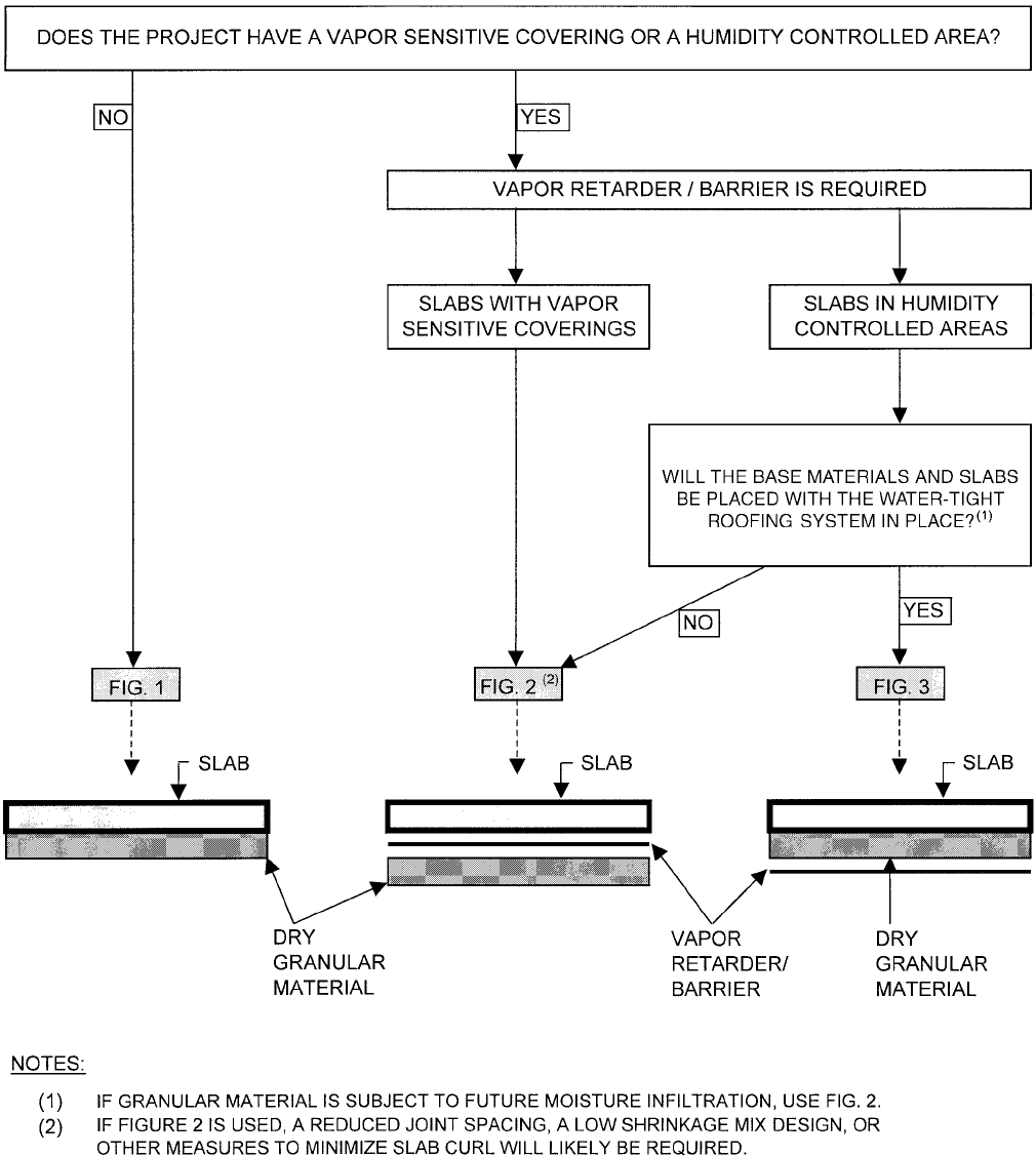
all appropriate parties before construction. Figure 3.1 can be
used to assist this evaluation process.
3.2.4 Reinforcement for crack-width control—Reinforce-
ment restrains movement resulting from slab shrinkage and
can actually increase the number of random cracks experi-
enced, particularly at wider joint spacing (Section 3.2.5.3).
Reinforcement in nonstructural slab-on-ground installations
is provided primarily to control the width of cracks that
occur (Dakhil, Cady, and Carrier 1975; CRSI 1990). This
reinforcement is normally furnished in the form of deformed
steel bars, welded wire reinforcing, steel fibers, or post-
302.1R-8 ACI COMMITTEE REPORT
tensioning tendons. Combinations of various forms of
reinforcement have proved successful.
Normally, the amount of reinforcement used in nonstruc-
tural slabs is too small to have a significant influence on
restraining movement resulting from volume changes. Refer
to Section 3.2.5 for a detailed discussion of the relationship
between joint spacing and amount of reinforcement.
Temperature and shrinkage cracks in unreinforced slabs-on-
ground originate at the surface of the slab and are wider at the
surface, narrowing with depth. For maximum effectiveness,
temperature and shrinkage reinforcement in slabs-on-ground
should be positioned in the upper third of the slab thickness.
The Wire Reinforcement Institute recommends that welded
wire reinforcement be placed 2 in. (50 mm) below the slab
Fig. 3.1—Decision flow chart to determine if a vapor retarder/barrier is required and where it is to be placed.
CONCRETE FLOOR AND SLAB CONSTRUCTION 302.1R-9
surface or within the upper third of slab thickness, whichever
is closer to the surface (CRSI 2001; Snell 1997). Rein-
forcement should extend to within 2 in. (50 mm) of the slab
side edge.
Deformed reinforcing steel or post-tensioning tendons
should be supported and tied together sufficiently to minimize
movement during concrete placing and finishing operations.
Chairs with sand plates or precast-concrete bar supports are
generally considered to be the most effective method of
providing the required support. When precast-concrete bar
supports are used, they should be at least 4 in. (100 mm)
square at the base, have a compressive strength at least equal
to the specified compressive strength of the concrete being
placed, and be thick enough to support reinforcing steel or
post-tensioning tendons at the proper elevation while main-
taining minimum concrete cover requirements.
When welded wire reinforcement is used, its larger flexi-
bility dictates that the contractor pay close attention to estab-
lishing and maintaining adequate support of the
reinforcement during the concrete placing operations.
Welded wire reinforcement should not be placed on the
ground and pulled up after placement of the concrete, nor
should the mats be walked in after placing the concrete.
Proper support spacing is necessary to maintain welded wire
reinforcement at the proper elevation; supports should be
close enough that the welded wire reinforcement cannot be
forced out of location by construction foot traffic. Support
spacing can be increased when heavier gage wires or a
double mat of small gage wires is used.
Reinforcing bars or welded wire reinforcement should be
discontinued at any joints where the intent of the designer is to
let the joint open and reduce the possibility of shrinkage and
temperature cracks in an adjacent panel. Where the reinforce-
ment is continued through the joint, cracks are likely to occur
in adjacent panels because of restraint at the joint (WRI/
CRSI 1991). When used in sufficient quantity, reinforce-
ment will hold out-of-joint cracks tightly closed. Some
designers prefer partial discontinuance of the reinforcement
at contraction joints to obtain some load-transfer capacity
without the use of dowel baskets. Refer to Section 3.2.7.
3.2.4.1 Steel fibers—In some installations, steel fibers
specifically designed for such use can be used with or
without conventional mild steel shrinkage and temperature
reinforcement in slab-on-ground floors. As in the case of
conventional reinforcement, steel fibers will not prevent
cracking of the concrete. Use of steel fibers through the
contraction joints reduces the width of joint openings and
that increases the likelihood of cracking occurring between
joints. The crack width, however, should remain narrow and,
in most cases, there are nondetectible microcracks providing
sufficient quantities of fibers used for the given slab joint
spacing and thickness, and subgrade conditions and concrete
material shrinkage properties are taken into consideration.
3.2.4.2 Synthetic fibers—Polypropylene, polyethylene,
nylon, and other synthetic fibers can help reduce segregation
of the concrete mixture and formation of shrinkage cracks
while the concrete is in the plastic state and during the first
few hours of curing. As the modulus of elasticity of concrete
increases with hardening of concrete, however, most
synthetic fibers at typical dosage rates recommended by the
fiber manufacturers will not provide sufficient restraint to
inhibit cracking.
3.2.4.3 Post-tensioning reinforcement The use of
high-strength steel tendons as reinforcement instead of
conventional mild steel temperature and shrinkage reinforce-
ment allows the contractor to introduce a relatively high
compressive stress in the concrete by means of post-
tensioning. This compressive stress provides a balance for
the crack-producing tensile stresses that develop as the
concrete shrinks during the curing process. Stage stressing,
or partial tensioning, of the slab on the day following place-
ment can result in a significant reduction of shrinkage
cracks. Construction loads on the concrete should be mini-
mized until the slabs are fully stressed (PTI 1990; PTI 1996).
For guidelines on installation details, contact a concrete floor
specialty contractor who is thoroughly experienced with this
type of installation.
3.2.4.4 Causes of cracking over reinforcement Plastic
settlement cracking over reinforcement is caused by inade-
quate consolidation of concrete, inadequate concrete cover
over the reinforcement, use of large diameter bars (Dakhil,
Cady, and Carrier 1975), higher temperature of reinforcing
bars exposed to direct sunlight, higher-than-required slump
in concrete, revibration of the concrete, inadequate curing of
the concrete, or a combination of these items.
3.2.5 Joint design—Joints are used in slab-on-ground
construction to limit the frequency and width of random cracks
caused by volume changes and to reduce the magnitude of slab
curling. Generally, if limiting the number of joints by
increasing the joint spacing can be accomplished without
increasing the number of random cracks, floor maintenance
will be reduced. The layout of joints and joint details should be
provided by the designer. If the joint layout is not provided, the
contractor should submit a detailed joint layout and placing
sequence for approval of the designer before proceeding.
As stated in ACI 360R, every effort should be made to
isolate the slab from restraint that might be provided by any
other element of the structure. Restraint from any source,
whether internal or external, will increase the potential for
random cracking.
Three types of joints are commonly used in concrete slabs-
on-ground: isolation joints, contraction joints, and construction
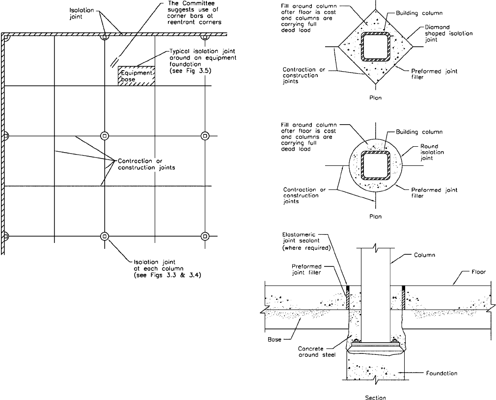
joints. Appropriate locations for isolation joints and contraction
joints are shown in Fig. 3.2. With the designer’s approval,
construction joint and contraction joint details can be inter-
changed. Refer to ACI 360R for a detailed discussion of
joints. Joints in topping slabs should be located directly over
joints in the base slab.
3.2.5.1 Isolation joints—Isolation joints should be used
wherever complete freedom of vertical and horizontal
movement is required between the floor and adjoining
building members. Isolation joints should be used at junc-
tions with walls (not requiring lateral restraint from the slab),
columns, equipment foundations, footings, or other points of
restraint such as drains, manholes, sumps, and stairways.
Isolation joints are formed by inserting preformed joint filler
302.1R-10 ACI COMMITTEE REPORT
between the floor and the adjacent member. The joint mate-
rial should extend the full depth of the slab and not protrude
above it. The joint filler will be objectionably visible where
there are wet conditions, or hygienic or dust-control require-
ments. Two methods of producing a relatively uniform depth
of joint sealant are as follows:
1) Score both sides of the preformed filler at the depth to
be removed by using a saw. Insert the scored filler in the
proper location and remove the top section after the concrete
hardens by using a screwdriver or similar tool.
2) Cut a strip of wood equal to the desired depth of the
joint sealant. Nail the wood strip to the preformed filler and
install the assembly in the proper location. Remove the wood
strip after the concrete has hardened.
Alternatively, a premolded joint filler with a removable
top portion can be used. Refer to Fig. 3.3 and 3.4 for typical
isolation joints around columns. Figure 3.5 shows an isolation
joint at an equipment foundation.
Isolation joints for slabs using shrinkage-compensating
concrete should be dealt with as recommended in ACI 223.
3.2.5.2 Construction joints—Construction joints are
placed in a slab to define the extent of the individual concrete
placements, generally in conformity with a predetermined joint
layout. If concreting is ever interrupted long enough for the
placed concrete to harden, a construction joint should be used.
If possible, construction joints should be located 5 ft (1.5 m) or
more from any other joint to which they are parallel.
In areas not subjected to traffic, a butt joint is usually
adequate. In areas subjected to hard-wheeled traffic, heavy
loadings, or both, joints with dowels are recommended
(Fig. 3.6). Refer to Section 3.2.7 for a detailed discussion on
dowel joints. Keyed joints are not recommended where load
transfer is required because the two sides of the keyway lose
contact when the joint opens due to drying shrinkage
(Section 3.2.7).
3.2.5.3 Contraction joints—Contraction joints are
usually located on column lines with intermediate joints
located at equal spaces between column lines as shown in
Fig. 3.2. The following factors are normally considered
when selecting spacing of contraction joints:
• Method of slab design (ACI 360R);
• Thickness of slab;
• Type, amount, and location of reinforcement;
• Shrinkage potential of the concrete (cement type and
quantity; aggregate size, quantity, and quality; w/cm;
type of admixtures; and concrete temperature);
• Base friction;
• Floor slab restraints;
• Layout of foundations, racks, pits, equipment pads,
trenches, and similar floor discontinuities;
• Environmental factors such as temperature, wind, and
humidity; and
Fig. 3.2—Appropriate locations for joints.
Fig. 3.3—Typical isolation joints at tube columns.

CONCRETE FLOOR AND SLAB CONSTRUCTION 302.1R-11
• Methods and quality of concrete curing.
As previously indicated, establishing slab joint spacing,
thickness, and reinforcement requirements is the responsi-
bility of the designer. The specified joint spacing will be a
principal factor dictating both the amount and the character
of random cracking to be experienced, so joint spacing
should always be carefully selected.
Curling of the floor surface at joints is a normal consequence
of volume change resulting from differential moisture loss
from concrete slab to the surrounding environment. This
distortion can result in conflict with respect to installation of
some floor coverings in the months after concrete placement.
Current national standards for ceramic tile and wood
flooring, such as gymnasium floors, are two instances that
require the concrete slab surface to comply with stringent
surface tolerances that cannot be met under typical slab
curling behavior. The designer should consider the require-
ments for successful installation of floor coverings contained
in Division 9 of the project specifications when performing
the concrete slab design (ACI 360R).
For unreinforced, plain concrete slabs, joint spacings of 24
to 36 times the slab thickness, up to a maximum spacing of
18 ft (5.5 m), have produced acceptable results. Some
random cracking should be expected; a reasonable level
might be random visible cracks to occur in 0 to 3% of the
surface area floor slab panels formed by saw-cutting,
construction joints, or a combination of both. If slab curl is
of greater concern than usual, joint spacing, mixture propor-
tion, and joint details should be carefully analyzed.
Joint spacing in nominally reinforced slabs (approximately
0.2% steel placed within 2 in. [50 mm] of the top of the slab)
can be increased somewhat beyond that recommended for
unreinforced, plain concrete slabs, but the incidence of random
cracking and curling will increase. Reinforcement will not
prevent cracking. If the reinforcement is properly sized and
located, cracks that do occur should remain tightly closed.
Contraction joints can be reduced or eliminated in slabs
reinforced with at least 0.5% continuous reinforcing steel
placed within 2 in. (50 mm) of the top of the slab or upper
one-third of slab thickness, whichever is closer to the slab
top surface. This will typically produce a larger number of
closely spaced fine cracks throughout the slab.
Joints in either direction can be reduced or eliminated by
post-tensioning that introduces a net compressive force in
the slab after all tensioning losses.
The number of joints can also be reduced with the use of
shrinkage-compensating concrete; however, the recommen-
dations of ACI 223 should be carefully followed.
Contraction joints should be continuous, not staggered or
offset. The aspect ratio of slab panels that are unreinforced,
reinforced only for shrinkage and temperature, or made with
shrinkage-compensating concrete should be a maximum of
1.5 to 1; however, a ratio of 1 to 1 is preferred. L- and T-
shaped panels should be avoided. Figure 3.7 shows various
types of contraction joints. Floors around loading docks have
a tendency to crack due to their configuration and restraints.
Fig. 3.4—Typical isolation joint at wide flange column.
Fig. 3.5—Typical isolation joint around an equipment
foundation.
Fig. 3.6—Typical doweled construction joint.

302.1R-12 ACI COMMITTEE REPORT
Figure 3.8 shows two methods that can be used to minimize
slab cracking at reentrant corners of loading docks.
Plastic or metal inserts are not recommended for
constructing or forming a contraction joint in any exposed
floor surface that will be subjected to wheeled traffic.
3.2.5.4 Saw cutting joints—Contraction joints in industrial
and commercial floors are usually formed by sawing a
continuous slot in the slab to result in a weakened plane,
below which a crack will form (Fig. 3.7). Further details on
saw cutting of joints are given in Section 8.3.12
3.2.6 Joint filling—Contraction and construction joints in
floor areas subject to the hard wheels of material handling
vehicle traffic should be filled with a semirigid filler to
minimize wear and damage to joint edges. Construction joints
should be saw-cut 1 in. (25 mm) deep before filling. Joints
should be as narrow as possible to minimize damage due to
wheels loads while still being wide enough to be properly filled.
Where wet conditions or hygienic requirements exist, joints
should be sealed with an elastomeric liquid sealant or a
preformed elastomeric device. If there is also industrial vehic-
ular traffic in these areas, consideration should be given to
strengthening the edge of the joint through alternative means.
Refer to Section 5.12 for a discussion of joint materials,
Section 9.10 for installation of joint fillers, and ACI 504R for
joint sealants.
3.2.7 Load-transfer mechanisms—Doweled construction
and contraction joints (Fig. 3.6 and 3.9) are recommended
when load transfer is required, unless a sufficient
post-tensioning force is provided across the joint to transfer
the shear. Dowels force the concrete sections on both sides of
a joint to undergo approximately equal vertical displacements
subjected to a load and help prevent damage to an exposed
edge when the joint is subjected to vehicles with hard-wheels
such as forklifts. Table 3.1 provides recommended dowel
sizes and spacing for round, square, and rectangular dowels.
For dowels to be effective, they should be smooth, aligned,
and supported so they will remain parallel in both the horizontal
and the vertical planes during the placing and finishing opera-
tion. All dowels should be sawn and not sheared. Properly
aligned, smooth dowels allow the joint to open as concrete
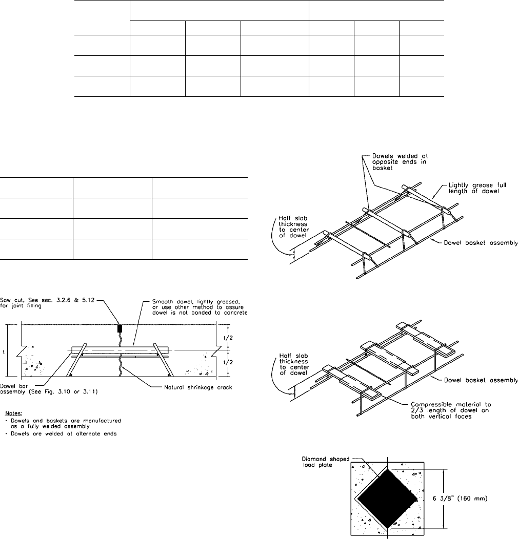
shrinks. Dowel baskets (Fig. 3.9 to 3.11) should be used to
maintain alignment of dowels in contraction joints, and
alignment devices similar to the one shown in Fig. 3.6 should
be used when detailing the doweled construction joints.
Dowels should be placed no closer than 12 in. (300 mm)
from the intersection of any joints.
Diamond-shaped load plates (a square plate turned so that
two corners line up with the joint, Fig. 3.12) can be used to
replace dowels in construction joints (Walker and Holland
1998). The diamond shape allows the slab to move horizontally
without restraint when the slab shrinkage opens the joint
(Fig. 3.13). Table 3.2 provides the recommended size and
Fig. 3.7—Saw-cut contraction joint.
Fig. 3.8—Joint details at loading dock.
CONCRETE FLOOR AND SLAB CONSTRUCTION 302.1R-13
spacing of diamond-shaped load plates. This type of load-
transfer device can be placed within 6 in. (150 mm) of an
intersection (Fig. 3.13). Square and rectangular dowels
cushioned on the vertical sides by a compressible material
also permit movement parallel and perpendicular to the joint
(Fig. 3.14). These types of load-transfer devices are useful in
other slab types where the joint should have load-transfer
capability while allowing some differential movement in the
direction of the joint, such as might be necessary in
post-tensioned and shrinkage-compensating concrete slabs
or in slabs with two-directional doweling (Schrader 1987).
In saw-cut contraction joints, aggregate interlock should not
be relied upon for effective load transfer for wheeled traffic
if the expected joint width exceeds 0.035 in. (0.9 mm)
(Colley and Humphrey 1967).
Deformed reinforcing bars should not be used across
contraction joints or construction joints because they restrain
joints from opening as the slab shrinks during drying.
Continuation of a part of the slab reinforcing through
contraction joints can provide some load-transfer capability
without using dowels but significantly increases the probability
of out-of-joint random cracking.
Round, square, and rectangular dowels for slab-on-ground
installation should meet ASTM A 36. The diameter or cross-
sectional area, length, shape, and specific location of dowels
as well as the method of support should be specified by the
designer. Refer to Table 3.1 and Fig. 3.9 to 3.14.
Fig. 3.9—Typical doweled contraction joint.
Fig. 3.10—Dowel basket assembly.
Table 3.1—Dowel size and spacing for round, square, and rectangular
dowels (ACI Committee 325 1956)
Slab depth, in.
(mm)
Dowel dimensions
*
, in. (mm)
Dowel spacing
center-to-center, in. (mm)
Round Square Rectangular
†
Round Square Rectangular
5 to 6
(125 to 150)
3/4 x 14
(19 x 350)
3/4 x 14
(19 x 350)
3/8 x 2 x 12
(10 x 50 x 300)
12 (300) 14 (350) 19 (475)
7 to 8
(175 to 200)
1 x 16
(25 x 400)
1 x 16
(25 x 400)
1/2 x 2-1/2 x 12
(12 x 60 x 300)
12 (300) 14 (350) 18 (450)
9 to 11
(225 to 275)
1-1/4 x 18
(30 x 450)
1-1/4 x 18
(30 x 450)
3/4 x 2-1/2 x 12
(19 x 60 x 300)
12 (300) 12 (300) 18 (450)
*
Total dowel length includes allowance made for joint opening and minor errors in positioning dowels.
†
Rectangular plates are typically used in contraction joints.
Notes: Table values based on a maximum joint opening of 0.20 in. (5 mm). Dowels must be carefully aligned and supported during
concrete operations. Misaligned dowels cause cracking.
Table 3.2—Dowel size and spacing for diamond-
shaped load plates
Slab depth, in. (mm)
Diamond load plate
dimensions, in. (mm)
Diamond load plate spacing
center-to-center, in. (mm)
5 to 6 (125 to 150)
1/4 x 4-1/2 x 4-1/2
(6 x 115 x 115)
18 (450)
7 to 8 (175 to 200)
3/8 x 4-1/2 x 4-1/2
(10 x 115 x 115)
18 (450)
9 to 11 (225 to 275)
3/4 x 4-1/2 x 4-1/2
(19 x 115 x 115)
20 (500)
Notes: Table values based on a maximum joint opening of 0.20 in. (5 mm). The
construction tolerances required make it impractical to use diamond-shaped load
plates in contraction joints.
Fig. 3.11—Rectangular load plate basket assembly.
Fig. 3.12—Diamond-shaped load plate at construction joint.

302.1R-14 ACI COMMITTEE REPORT
Keyed joints are not recommended for load transfer in
slabs-on-ground where heavy-wheeled traffic load is antici-
pated, because they do not provide effective load transfer.
When the concrete shrinks, the keys and keyways do not
retain contact and do not share the load between panels; this
can eventually cause a breakdown of the concrete joint
edges. For long post-tensioned floor strips and floors using
shrinkage-compensating concrete with long joint spacing, care
should be taken to accommodate significant slab movements.
In most instances, post-tensioned slab joints are associated
with a jacking gap. The filling of jacking gaps should be
delayed as long as possible to accommodate shrinkage and
creep (PTI 1990; PTI 2000). Where significant slab movement
is expected, steel plating of the joint edges is recommended;
for strengthening the edges (Fig. 3.15 and 3.16).
A doweled joint detail at a jacking gap in a post-tensioned
slab (ASTM 1994; Spears and Panarese 1992) is shown in
Fig. 3.16.
3.3—Suspended slabs
3.3.1 Required design elements—In addition to many of
the items listed in Section 1.1.2, the following items specifi-
cally impact the construction of suspended slabs and should
be included in the contract documents prepared by the
designer:
• Frame geometry (member size and spacing);
• Reinforcement (type, size, location, and method of
support);
• Shear connectors, if required;
• Construction joint location;
• Metal deck (type, depth, and gage), if required;
• Shoring, if required; and
• Tolerances (forms, structural steel, reinforcement, and
concrete).
3.3.2 Suspended slab types—In general, suspended floor
systems fall into four main categories:
1. Cast-in-place suspended floors;
2. Slabs with removable forms;
3. Slabs on metal decking; and
4. Topping slabs on precast concrete.
Design requirements for cast-in-place concrete suspended
floor systems are covered by ACI 318 and ACI 421.1R.
Refer to these documents to obtain design parameters for
various cast-in-place systems. Slabs on metal decking and
topping slabs on precast concrete are hybrid systems that
involve design requirements established by ANSI, ASCE,
The American Institute of Steel Construction, Precast/
Prestressed Concrete Institute, and tolerances of ACI 117.
The levelness of suspended slabs depends on the accuracy
of formwork and strikeoff but is further influenced (espe-
cially in the case of slabs on metal decking) by the behavior
of the structural frame during and after completion of
construction. Each type of structural frame behaves some-
what differently; it is important for the contractor to recog-
nize these differences and plan accordingly.
Fig. 3.14—Doweled joint detail for movement parallel and
perpendicular to the joint.
Fig. 3.13—Diamond-shaped load plates at slab corner.
Fig. 3.15—Typical armored construction joint detail.
Fig. 3.16—Typical doweled joint detail for post-tensioned slab.
CONCRETE FLOOR AND SLAB CONSTRUCTION 302.1R-15
The presence of camber in some floor members and the
ACI 117 limitation on tolerances in slab thickness dictate
that concrete be placed at a uniform thickness over the
supporting steel. When placing slabs on metal decking, the
contractor is cautioned that deflections of the structural steel
members can vary from those anticipated by the designer.
Achieving a level deflected surface can require increasing
the slab thickness more than 3/8 in. (9.5 mm) in local areas.
The committee recommends that concrete placement
procedures and the basis for acceptance of the levelness of a
completed concrete floor surface be established and agreed
upon by key parties before beginning suspended floor
construction (Tipping 1992).
3.3.3 Slabs with removable forms—Cast-in-place concrete
construction can be either post-tensioned or conventionally
reinforced. Both of these systems are supported during initial
concrete placement, and they will deflect when supporting
shores are removed.
Post-tensioned systems are normally used when larger
spans are necessary or when the structural system is relatively
shallow for the spans considered. Post-tensioned systems use
high-strength steel tendons that are tensioned using a
hydraulic jack designed for that purpose. The magnitude of
floor slab deflection after supports are removed is less than
that of comparable floors reinforced with conventional
deformed reinforcing steel. At times, dead load deflection is
entirely eliminated by the use of post-tensioning.
The magnitude of deflection in a conventionally mild steel
reinforced floor system is dependent on a number of variables
such as span, depth of structure, age at the time forms are
stripped, concrete strength, and amount of reinforcement. In
locations where the anticipated dead load deflection of a
member is deemed excessive by the designer, an initial
required camber, generally 1/2 in. (13 mm) or more, can be
required. The amount of camber is determined by the designer
based on an assessment of the loading conditions discussed.
Ideally, the cambered floor system will deflect down to a level
position after removal of the supporting shores.
3.3.4 Slabs on carton forms—Slabs on carton forms are a
special application of slabs with removable forms (Tipping
and North 1998). These slabs are necessary when slabs at
ground level should remain independent of soil movement.
Slabs on carton forms are most commonly used when soils at
the building site are expansive clays subject to significant
movement as a result of moisture variation. They provide a
more economical construction solution than conventional
framing systems, which require a crawl space to remove
forms. The cardboard carton forms deteriorate in the months
following construction, eventually leaving the desired void
space below the slab and forcing the slab to span between
supporting foundation elements.
Experience has shown that certain types of wet cardboard
carton forms can fail locally under the weight of concrete
and construction activities, with a resultant loss of part or all
of the desired void space in the vicinity of the form failure.
This failure can be instantaneous but can also occur 30 or
45 min after strikeoff. The latter type of failure, in addition
to reducing desired void space, can result in a loss of local
slab levelness. Forms that have been damaged by rain should
be replaced or allowed to dry thoroughly, with their capacity
verified, before placement of concrete.
3.3.5 Slabs on metal deck—Construction of slabs on metal
deck involves the use of a concrete slab and a supporting
platform consisting of structural steel and metal deck. The
structural steel can be shored or unshored at the time of
concrete placement, and the metal deck serves as a stay-in-
place form for the concrete slab. This construction can be
composite or noncomposite.
The supporting steel platform for slabs on metal deck is
seldom level. Variation in elevations at which steel beams
connect to columns and the presence of camber in some floor
members combine to create variations in the initial elevation
of steel members. Regardless of the initial levelness of the
steel frame, unshored frames will deflect during concrete
placement. These factors make the use of a laser or similar
instrument impractical for the purpose of establishing a
uniform elevation for strikeoff of the concrete surface of a
slab on metal deck, unless the frame is preloaded to allow
deflection to take place before strikeoff, and slab thickness is
allowed to vary outside norms dictated by ACI 117. The
presence of camber in some floor members and the ACI 117
limitation on variation in slab thickness generally dictates
that concrete be placed to a uniform thickness over the
supporting steel.
3.3.5.1 Composite slabs on metal deck—In composite
construction, the composite section (concrete slab and steel
beams) will work together to support any loads placed on the
floor surface after the concrete has hardened. Composite
behavior is normally developed through the use of shear
connectors welded to the structural steel beam. These shear
connectors physically connect the concrete slab to the beam
and engage the concrete slab within a few feet of the steel
beam; the resulting load-carrying element is configured much
like a capital T. The steel beam forms the stem of the T, and
the floor slab forms the cross-bar. Construction joints that are
parallel to structural steel beams should be located far enough
away to eliminate their impact on composite behavior.
Questions about the location of construction joints should be
referred to the designer on the project (Ryan 1997).
Unshored composite construction is the more common
method used by designers because it is less expensive than
shored construction. In unshored construction, the structural
steel beams are sometimes cambered slightly during the
fabrication process. This camber is intended to offset the
anticipated deflection of that member under the weight of
concrete. Ideally, after concrete has been placed and the
system has deflected, the resulting floor surface will be level
(Tipping 2002).
Shored composite concrete slabs on metal deck are similar
to slabs with removable forms in that both are supported
until the concrete has been placed and reaches the required
strength. Structural steel floor framing members for shored
composite slabs on metal deck are usually lighter and have
less camber than those used for unshored construction with
similar column spacings and floor loadings. One major
concern with shored composite construction is the tendency
302.1R-16 ACI COMMITTEE REPORT
for cracks wider than 1/8 in. (3 mm) to form in the concrete
slab when the supporting shores are removed. These cracks
do not normally impair the structural capacity of the floor but
can become a severe aesthetic problem. The contractor is
cautioned that this issue and any measures taken by the
designer to avoid the formation of this type of crack should
be addressed to the satisfaction of key parties before beginning
suspended floor construction.
3.3.5.2 Noncomposite slabs on metal deck—In noncom-
posite construction, the slab and supporting structural steel
work independently to support loads imposed after hard-
ening of the concrete slab.
3.3.6 Topping slabs on precast concrete—A cast-in-place
concrete topping on precast-prestressed concrete units
involves the use of precast elements as a combination form
and load-carrying element for the floor system. The cast-in-
place portion of the system consists of a topping of some
specified thickness placed on top of the precast units. The
topping can be composite or noncomposite. In either case,
added deflection of precast units under the weight of the
topping slab is normally minor, so the finished surface will
tend to follow the surface topography established by the
supporting precast units. The camber in precast members, if
they are prestressed, can change with time as a result of
concrete creep. Depending on the length of time between
casting of precast units and erection, this potential variation
in camber of similar members can create significant challenges
for the contractor. Care should be taken in the scheduling of
such operations to minimize the potential impact of these
variations. Precast members are less flexible and adaptable
to changes or modifications that can be required on the
jobsite than are the previously discussed systems.
3.3.7 Reinforcement—For cast-in-place concrete suspended
slabs, reinforcing steel location varies as dictated by the
contract documents. Post-tensioning reinforcement, when
used, is enclosed in a plastic or metal sleeve and is tensioned
by a hydraulic jack after the concrete reaches sufficient
compressive strength. Elongation and subsequent anchoring
of the ends of post-tensioning tendons results in the transfer
of compressive force to the concrete (PTI 1990).
For slabs on metal deck, reinforcement is normally
provided by deformed reinforcing steel, welded wire reinforce-
ment, or a combination thereof.
3.3.8 Construction joints—The designer should provide
criteria for location of construction joints in suspended slabs.
The following is a general discussion of criteria that can
influence these decisions.
3.3.8.1 Slabs on removable forms—Construction joints
can introduce weak vertical planes in an otherwise monolithic
concrete member, so they should be located where shear
stresses are low. Under most gravity load conditions, shear
stresses in flexural members are low in the middle of the span.
ACI 318 requires that construction joints in floors be located
within the middle third of spans of slabs, beams, and primary
beams. Joints in girders should be offset a minimum distance
of two times the width of any intersecting beams.
3.3.8.2 Composite slabs on metal deck—An important
consideration when deciding on the location of construction
joints in composite slabs on metal deck is that the joint location
can influence deflection of the floor framing near the joint.
A composite member (steel beam and hardened concrete
slab working together) is stiffer and, therefore, deflects less
than a noncomposite member (steel beam acting alone).
Most composite slabs on metal deck are placed on an
unshored structural steel floor frame. Often, structural steel
members have initial camber to offset anticipated noncom-
posite deflection resulting from concrete placement. After
hardening of the concrete, however, the composite member
deflects much less than a comparable noncomposite beam or
primary beam.
Following are general guidelines for deciding on the location
of construction joints in composite slabs on metal deck:
1. Construction joints that parallel secondary structural
steel beams should normally be placed near the midspan of
the slab between beams;
2. Construction joints that parallel primary structural steel
beams and cross secondary structural steel beams should be
placed near the primary beam. The primary structural steel
beam should not be included in the initial placement. It is
important to place the construction joint far enough away from
the primary beam to allow sufficient distance for development
of the primary beam flange width. Placing the construction
joint a distance of 4 ft (1.2 m) from the primary beam is
usually sufficient for this purpose. This construction joint
location allows nearly the full dead load from concrete place-
ment to be applied to secondary beams that are included in the
initial concrete placement. The primary beam should gener-
ally be included in the second placement at the construction
joint. This will allow the primary beam to deflect completely
before concrete at the primary beam hardens; and
3. Construction joints that cross primary structural steel
beams should be placed near a support at one end of the
primary beam. This will allow the beam to deflect
completely before concrete at the beam hardens.
3.3.8.3 Noncomposite slabs on metal deck—The place-
ment of construction joints in noncomposite slabs on metal
deck should follow the same general guidelines discussed for
slabs on removable forms in Section 3.3.7.1.
3.3.8.4 Topping slabs on precast concrete—Construc-
tion joints in topping slabs on precast concrete should be
placed over joints in the supporting precast concrete.
3.3.9 Cracks in slabs on metal deck—Cracks often
develop in slabs on metal deck. These cracks can result from
drying shrinkage and thermal contraction or variations in
flexibility of the supporting structural steel and metal deck.
In a composite floor framing system, primary beams are the
stiffest elements and generally deflect less than secondary
beams. The most flexible part of the floor framing assembly
is the metal deck, which is often designed for strength rather
than for flexibility consideration.
Vibration as a result of power floating and power troweling
operations can produce cracking over the structural steel
beams during concrete finishing operations if the metal deck
is flexible. As the concrete cures and shrinks, these cracks
will open wide if not restrained by reinforcing steel, usually
CONCRETE FLOOR AND SLAB CONSTRUCTION 302.1R-17
welded wire reinforcement, located near the top surface of
the slab.
3.4—Miscellaneous details
3.4.1 Heating ducts—Heating ducts embedded in a
concrete slab can be of metal, rigid plastic, or wax-impreg-
nated cardboard. Ducts with waterproof joints are recom-
mended. When metal ducts are used, calcium chloride
should not be used in the concrete. Refer to Section 5.7.3 for
a discussion on chlorides in concrete and Section 4.5.2 for
installation of heating ducts.
3.4.2 Edge insulation—Edge insulation for slabs-on-
ground is desirable in most heated buildings. The insulation
should be in accordance with ASHRAE 90.1. It should not
absorb moisture and should be resistant to fungus, rot, and
insect damage; it should not be easily compressed.
Insulation should preferably be placed vertically on the
inside of the foundation. It can also be placed in an L-shape
configuration adjacent to the inside of the foundation and
under the edge of the slab. If the L-shape configuration is
used, the installation should extend horizontally under the
slab a total distance of 24 in. (600 mm).
3.4.3 Radiant heating: piped liquids—Slabs can be heated
by circulating heated liquids through embedded piping.
Ferrous, copper, or plastic pipe is generally used with
approximately 2 in. (50 mm) of concrete cover (not less than
1 in. [25 mm]) under the pipe and with 2 to 3 in. (50 to 75 mm)
of concrete cover over the pipe. The slab is usually monolithic
and the concrete is placed around the piping, which is fixed in
place. Two-course slab construction has also been used,
wherein the pipe is laid, connected, and pressure tested for
tightness on a hardened concrete base course. Too often,
however, the resulting cold joint is a source of distress during
the service life.
Insulating concrete made with vermiculite or perlite
aggregate or cellular foam concrete can be used as a
subfloor. The piping should not rest directly on this or any
other base material. Supports for piping during concreting
should be inorganic and nonabsorbent; precast concrete bar
supports (Section 3.2.4) are preferred to random lengths of pipe
for use as supports and spacers. Wood, brick, or fragments of
concrete or concrete masonry should not be used.
Sloping of the slab, where possible, can simplify
sloping of the pipe. Reinforcement, such as welded wire
reinforcement, should be used in the concrete over the
piping. Where pipe passes through a contraction or
construction joint, a provision should be made for
possible movement across the joint. The piping should
also be protected from possible corrosion induced by
chemicals entering the joint. The piping should be pres-
sure-tested before placing concrete, and air pressure (not
water pressure) should be maintained in the pipe during
concreting operations. After concreting, the slab should
not be heated until curing is complete. The building owner
should be warned to warm the slabs gradually using luke-
warm liquid in the system to prevent cracking of the cold
concrete.
3.4.4 Radiant heating: electrical—In some electrical
radiant heating systems, insulated electrical cables are laid
singly in place within the concrete or fastened together on
transverse straps to form a mat. One system employs cable
fastened to galvanized wire sheets or hardware cloth. The
cables are embedded 1 to 3 in. (25 to 75 mm) below the
concrete surface, depending on their size and operating
temperature. In most systems the wires, cables, or mats are
laid over a bottom course of unhardened concrete, and the
top course is placed immediately over this assemblage with
little lapse of time, thus avoiding the creation of a horizontal
cold joint (ASHVE 1955).
Calcium chloride should not be used where copper wiring is
embedded in the concrete; damage to insulation and subsequent
contact between the exposed wiring and reinforcing steel
will cause corrosion. If admixtures are used, their chloride
contents should comply with the limits recommended by
ACI 222R.
3.4.5 Snow-melting—Systems for melting snow and ice
can be used in loading platforms or floor areas subjected to
snow and ice. The concrete should be air-entrained for
freezing-and-thawing resistance. Concrete surfaces should
have a slope not less than 1/4 in./ft (20 mm/m) to prevent
puddles from collecting. Piping systems should contain a
suitable liquid heat-transfer medium that does not freeze at
the lowest temperature anticipated. Calcium chloride should
not be used (Section 5.7.3). Experience has shown that these
snow-melting piping systems demand high energy consump-
tion while displaying a high potential for failure and thermal
cracking. The most successful applications appear to have
been at parking garage entrances.
Some electrical systems are in use. These internally heated
snow-melting systems have not been totally satisfactory.
3.4.6 Pipe and conduit—Water pipe and electrical conduit,
if embedded in the floor, should have at least 1-1/2 in. (38 mm)
of concrete cover on both the top and bottom.
3.4.7 Slab embedments in harsh environments—Care
should be exercised in using heating, snow-melting, water,
or electrical systems embedded in slabs exposed to harsh
environments such as parking garages in northern climates
and marine structures. If not properly embedded, systems
can accelerate deterioration by increasing seepage of salt-
water through the slab or by forming electrical corrosion
circuits with reinforcing steel. If concrete deterioration
occurs, the continuity and effective functioning of embedded
systems are invariably disrupted.
