
Fotolia/...
Relays and Optocouplers
Versatile Oering for Every Application
Table of Contents
Overview 3
Features and Advantages 5
Selection Criteria for Relays 7
859 Series 9
857 Series 13
788 Series 17
858 Series 21
859, 857, 788, 858 Series Accessories 24
2042 Series 25
Functional Safety 29
Glossary 31
Connection Technology 34
2

RELAYS AND OPTOCOUPLERS
Overview
3
WAGO provides a broad range of relays and
optocouplers to support applications where
electrical signals must be transmitted, isolated,
adjusted or amplied. To perform these tasks
many cost-eective solutions are available in
easy to install packages.
A wide product oering includes dierent
housing options, wide voltage ranges,
switchable loads from 1 mA to 16 A, pluggable
relays, easy termination of conductors from 28-
12 AWG and several accessories designed to
optimize machine safety and uptime.
ADVANTAGES:
• Jumpering capabilities
• Reliability
• Compact design to maximize cabinet space
• Wide product oering accommodates most applications
• Easy to install

4
859 Series 857 Series 788 Series
WAGO RELAYS AND OPTOCOUPLERS
858 Series 2042 Series

iStock.com/ lagereek
FEATURES AND ADVANTAGES
Relays/Optocouplers
Relay or Optocoupler?
Relay Optocoupler/Solid-State Relay
• Electrically isolate input and output circuits • Adjust dierent signal levels • Amplify and/or multiply signals
Immunity to electromagnetic interference and transient voltages
Long service life – no mechanical wear on contacts
High, short-term overload on both input and output sides without losing
functionality
High switching frequency due to short switch-on and switch-o times
Minimal switching loss/high switching power Immune to shock and vibration
A single module switches both DC and AC
(highly versatile)
No contact bouncing
No leakage current in the load circuit “Noiseless” switching
Multiple contacts possible
(control signal switches multiple load circuits)
Low control power
Switching state is partially visible to the naked eye Short response times
Safe isolation between coil and contact set
No electromagnetic radiation from switching sparks or coils – no
interference with adjacent modules or electronic components during
switching
5

Distinguishing between Optocoupler and Solid-State Relay
Optocoupler Solid-State Relay
Mounted or soldered to the PCB
- Not replaceable
Pluggable on socket
- Can be replaced in case of repair
A large number of variants enhances application exibility and range Seamless change from electronic to electromechanical switching element
©leungchopan/Fotolia.com
6

7
SELECTION CRITERIA FOR RELAYS
It’s in the Details
1) Coil
Coil voltage; maximum continuous voltage;
response voltage and pick-up current;
drop-o voltage and dropout current
In industrial applications, relays are proven to handle
a variety of tasks. However, some points must be
considered when selecting the right relay module . These
points include the nominal voltage of the coil, as well as
the number of relay break contacts, make contacts and
changeover contacts. The contacts are important for
the service life. The contact material has to be selected
depending on whether inductive, capacitive or resistive
loads will be connected.
2) Contacts
Contact arrangement; contact loading;
contact material; service life; contact resistance;
isolation requirements; limiting continuous current
5) Other criteria
Ambient temperature;
dielectric strength;
mounting conditions,
IP degree of protection;
approvals

©Friedberg/Fotolia.com
iStock.com/Bartosz Hadyniak ©Netzer Johannes/Fotolia.com
8
SELECTION CRITERIA FOR RELAYS
3) Switching time
Response time; drop-out time;
switching frequency; bounce time
4) Mechanical properties
Vibration resistance; shock resistance;
size and space

With a large variety of relays and optocouplers, the 859 Series will suit any industrial interface appli-
cation. The compact housing is ideal for space-restricted control panels. Simple commoning at the
control and load-side level saves valuable wiring time and reduces errors.
• 6 mm wide housing for DIN rail mounting
• Jumpering capabilities
• LED indication
• Integrated test port at each termination
• Marking options
• Custom solutions available - please contact factory
rg1
Within railway applications, there are special requirements for relays including operating voltage,
ambient temperature and shock/vibration resistance: Relays from WAGO meet these requirements.
©TTstudio/Fotolia.com
859 SERIES
6 mm Wide Terminal Blocks with
Soldered PCB Relays or Optocouplers
9

10
Vibration-proof - fast - maintenance-free
CAGE CLAMP® COMPACT handling for all types of conductors
Solid Stranded Ferruled
CAGE CLAMP® COMPACT

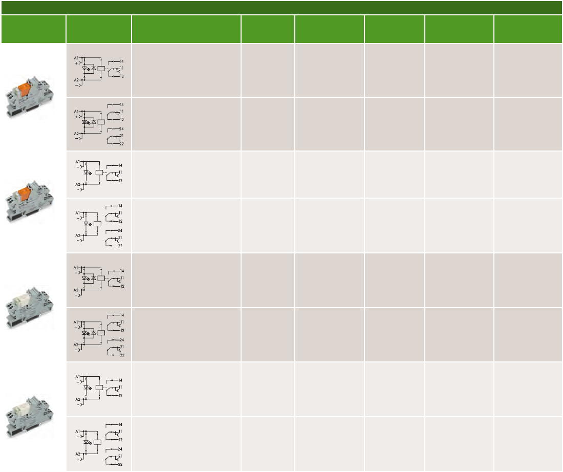
859 Series - 6 mm Wide Terminal Blocks with Soldered PCB Relays
Circuit
Diagram
Description Item No.
Nominal Input
Voltage
Max. Switching
Voltage
Max. Continuous
Current
Approvals
A1
+
14
12
11
A2
–
Relay with SPDT
(1 C/O)
859-302
859-303
859-304
859-305
859-306
859-307
859-308
5 VDC
12 VDC
24 VDC
48 VDC
60 VDC
110 VDC
220 VDC
250 VAC 5 A
r g 1
14
12
11
A1
A2
Relay with SPDT
(1 C/O)
859-353
859-354
859-355
859-357
859-358
12 VAC/VDC
24 VAC/VDC
48 VAC/VDC
115 VAC/VDC
230 VAC/VDC
250 VAC 5 A
r g 1
A1
+
14
12
11
A2
–
Relay with SPDT (1 C/O),
with gold contacts
859-314 24 VDC
250 VAC*
5 A*
r g 1
Relay with SPDT (1 C/O),
with gold contacts,
extended input voltage,
and temperature range
859-392
859-386
859-317
24 VDC
36 VDC
115 VDC
250 VAC*
3 A*
r g 1
14
12
11
A1
~
A2
~
Relay with SPDT (1 C/O),
with gold contacts
859-359 230 VAC
250 VAC*
5 A*
r g 1
Relay with SPDT (1 C/O),
with gold contacts
859-360 115 VAC
250 VAC*
5 A*
Relay with SPDT (1 C/O) 859-367 115 VAC
250 VAC
5 A
r g 1
14
12
11
A1
~
A2
~
Relay with SPDT (1 C/O),
with specied turn-on and
turn-o threshold
859-368 230 VAC
250 VAC
5 A
r g 1
14
12
11
A1
+
A2
–
Relay with SPDT (1 C/O),
with extended input
voltage and temperature
range
859-390 24 VDC
250 VAC
3 A
r g 1
14
12
11
A1
+
A2
–
Relay with SPDT (1 C/O),
with extended input
voltage and temperature
range
859-391 110 VDC
250 VAC
3 A
r g 1
Relay with SPDT (1 C/O),
with extended input
voltage and temperature
range
859-398
859-394
859-397
859-393
859-399
24 VDC
36 VDC
48 VDC
72 VDC
110 VDC
250 VAC
3 A
r g 1
* To avoid damage to the gold layer, the specied switching voltages and switching currents should not be exceeded.
The evaporation of the gold layer can reduce the life of the relay.
11

859 Series - 6 mm Wide Terminal Blocks with Soldered Optocoupler
Circuit
Diagram
Description Item No.
Nominal Input
Voltage
Max. Switching
Voltage
Max. Continuous
Current
Approvals
A1
+
A2
–
1
+
2
–
R
L
Optocouplers with ex-
tended output voltage
and temperature range
for railway applications
859-793 5 VDC 3 ... 60 VDC 100 mA
r g 1
A1
+
A2
–
1
+
2
–
R
L
Optocouplers with ex-
tended output voltage
and temperature range
for railway applications
859-791
859-794
24 VDC
24 VDC
7 ... 60 VDC
9 ... 60 VDC
100 mA
100 mA
r g 1
A1
+
A2
–
1
+
2
–
R
L
Optocoupler
859-796 24 VDC 3 ... 30 VDC 100 mA
r g 1
A1
+
A2
–
1
+
2
–
R
L
859-795 5 VDC 3 ... 30 VDC 100 mA
r g 1
A1
+
A2
–
R
L
0V
A
24V
Optocoupler, negative
switching, power optocou-
pler
859-720 24 VDC 10 ... 30 VDC 100 mA
r g 1
A1
+
A2
–
R
L
+A
-2
-2
Optocoupler, power opto-
coupler
859-730 24 VDC 3 ... 30 VDC 3 A
r g 1
13+
14
A2
−
A1
+
Optocoupler, power opto-
coupler
859-740 24 VDC 3 ... 30 VDC 3 A
r g 1
A1
+
A2
–
R
L
+A
-2
Optocoupler, power opto-
coupler
859-744 12 ... 48 VDC 3 ... 53 VDC 4 A
r g 1
R
L
1
+
3
2
–
24 V
A
0 V
A2
~
A1
~
Optocoupler PNP,
increased input voltage,
frequency to 100 Hz, input
voltage up to 270 VAC
859-772 230 VAC 20 ... 30 VDC 500 mA
r g 1
A2
~
A1
~
0 V
+24 V
A
R
L
Optocoupler, negative
switching
859-712 24 VDC 20 ... 30 VDC 500 mA
r g 1
A2
—
A1
+
0 V
+24
V
A
R
L
Optocoupler, negative
switching
859-702 5 VDC 20 ... 30 VDC 500 mA
r g 1
A2
—
A1
+
0 V
+24
V
A
R
L
Optocoupler, negative
switching
859-708 24 VDC 20 ... 30 VDC 500 mA
r g 1
A2
—
A1
+
0 V
+5 V
A
R
L
Optocoupler, negative
switching
859-706 24 VDC 4 ... 6.25 VDC 500 mA
r g 1
A2
—
A1
+
0 V
+24 V
A
R
L
Optocoupler, positive
switching
859-752 5 VDC 20 ... 30 VDC 500 mA
r g 1
A2
—
A1
+
0 V
+24 V
A
R
L
Optocoupler, positive
switching
859-758 24 VDC 20 ... 30 VDC 500 mA
r g 1
Optocoupler, positive
switching
859-756 24 VDC 4 ... 6.25 VDC 500 mA
r g 1
Optocoupler 859-902 5 VDC 24 ... 260 VAC 500 mA
r g 1
12

With a common prole and 6 mm-wide housing, 857 Series relays and optocouplers provide a pow-
erful compact solution for switching applications. An optional interface adapter plugs into the input
or output side, combining eight modules to reduce wiring time and errors.
• Pluggable relays or optocouplers
• Jumpering capabilities
• LED indication
• Wide input voltage range (5 - 230 VAC/VDC versions)
• Up to 6 A switching current
• Marking options
• Can be used with 857 Series signal conditioners
rg1
4 ANSI .
857 SERIES
6 mm Wide Terminal Block Style with
Pluggable PCB Relays or Optocouplers
13

14
Push-in CAGE CLAMP®
Vibration-proof - fast - maintenance-free
Push-in CAGE CLAMP® handling for all types of conductors
StrandedSolid Ferruled

857 Series - 6 mm Wide Sockets with Pluggable PCB Relays or Optocouplers
Circuit
Diagram
Description Item No.
Nominal Input
Voltage
Max. Switching
Voltage
Max. Continuous
Current
Approvals
Relay with SPDT (1 C/O)
857-303
857-304
857-305
857-306
12 VDC
24 VDC
48 VDC
60 VDC
250 VAC 6 A
r g 1
4 ANSI .
A2
A1
857-354
857-357
857-358
857-359
24 VAC/VDC
115 VAC/VDC
230 VAC/VDC
24 ... 230 VAC/VDC
250 VAC 6 A
r g 1
4 ANSI .
Relay with SPDT (1 C/O),
with gold contacts
857-314 24 VDC 250 VAC* 6 A**
r g 1
4 ANSI .
A2
A1
857-364
857-367
857-368
857-369
24 VAC/VDC
115 VAC/VDC
230 VAC/VDC
24 ... 230 VAC/VDC
250
VAC
*
6 A**
r g 1
4 ANSI .
13
N.
C.
14
Optocouplers
857-704 24 VDC
0 ... 48
VDC
100 mA
r 1
4 .
857-707 115 VAC/VDC 0 ... 48 VDC
100
mA
r 1
4 .
13
14
N.C.
A2
A1
857-708
230 VAC/VDC 0 ... 48 VDC 100 mA
r 1
4 .
13
14
N.
C.
Optocouplers
857-714
24 VDC 24 ... 240 VAC 1 A
r 1
4 .
857-717 115 VAC/VDC 24 ... 240 VAC 1 A
r 1
4 .
A2
A1
13
14
N.C.
857-718
230 VAC/VDC 24 ... 240 VAC 1 A
r 1
4 .
13
14
N.
C.
Optocouplers
857-724 24 VDC 0 ... 24 VDC 2 A
r 1
4 .
857-727 115 VAC/VDC 0 ... 24 VDC 2 A
r 1
4 .
A2
A1
13
14
N.C.
857-728
230 VAC/VDC 0 ... 24 VDC 2 A
r 1
4 .
** To avoid damage to the gold layer, the specied switching voltages and switching currents should not be exceeded.
The evaporation of the gold layer can reduce the life of the relay.
15

857 Series - 6 mm Wide Sockets with Pluggable PCB Timer Relays
Circuit
Diagram
Description Item No.
Input Voltage
Range
Output Voltage
Range
Max. Continuous
Current
Approvals
A1+
A2–
S1 … S4
14
11
12
24 V
5 V
μC
Multifunction timer with
SPDT (1 C/O), 4 functions,
4 time ranges: 0.1 s ... 30
min
857-604
16.8 … 31.2
VDC 250 VAC 6 A
r 1
A1+
A2–
S1 … S4
14
R
L
13
+
N.C.
24 V
5 V
μC
Solid -state relay with 1 NO
contact, 4 functions, 4 time
ranges: 0.1 s ... 30 min
857-624
20.4 … 31.2
VDC 0 … 24 VAC 2 A
r 1
A1+
A2–
S1 … S4
14
R
L
13
+
N.C.
24 V
5 V
μC
Solid -state relay with 1 NO
contact, 4 functions, 4 time
ranges: 0.1 s ... 30 min
857-634
20.4 … 31.2
VDC 24 … 230 VAC 1 A
r 1
U
S
GND
DO
S1 … S10
St
14
11
12
24 V
5 V
μC
Multifunction timer with
SPDT (1 C/O), 14 functions,
8 time ranges
857-640
16.8 … 31.2
VDC 250 VAC 6 A
r 1
U
S
GND
DO
S1 … S10
St
14
11
12
24 V
5 V
μC
Multifunction timer with
SPDT (1 C/O), 7 functions,
2 x 8 time ranges
857-642
16.8 … 31.2
VDC
250
VAC 6 A
r 1
857 Series - 8 - Port Interface Adapter for System Wiring
Circuit
Diagram
Description Item No.
Input Voltage
Range
Current Carrying
Capacity
Max. Continuous
Current
Approvals
1
2
3+―
4
5
6
7
8
9
10
11
12
13
14
Interface
FLK 14
8-port adapter, with 14 -pin
ribbon cable connectors,
input positive switching **
857-981 24 VDC 1 A 2.5 A
Y g
1
2
3+―
4
5
6
7
8
9
10
11
12
13
14
Interface
FLK 14
8-port adapter, with 14-pin
ribbon cable connectors,
output PNP ***
857-982 24 VDC 1 A 2.5 A
Y g
+―1
9
Interface
SUB-D
8-port adapter, with D-sub
male connector, input with
15-pin ribbon cable plug
connectors, plus switching
**
857-986 24 VDC 1 A 2.5 A
g
** Use on the coil side of the 857 - socket *** Use the contact page of the 857 - socket
857 Series - 6 mm Wide Sockets with Pluggable PCB Relays - Base Load Module for Long Cable Runs or 2-wire Sensors or Capacitive Loads
Circuit
Diagram
Description Item No.
Input Voltage
Range
Output Voltage
Range
Max. Continuous
Current
Approvals
A1
A2
14
11
12
Relay with SPDT (1 C/O)
with integrated base load
module
857-358
/006-000
230 VAC
250 VAC
6 A
1
A1
A2
14
11
12
Relay with SPDT (1 C/O)
with integrated base load
module and gold-plated
contacts
857-368
/006-000
230 VAC
250 VAC
6 A
1
16

788 Series pluggable PCB relay modules provide and excellent cost-eective
platform for industrial and process automation applications. A robust, easy-to-
use lever simplies replacement.
• Relays with SPDT (1 C/O) or DPDT (2 C/O)
• Up to 16 A and 250 V of switching power
• DIN rail mount
• Pluggable LED indicator
• Integrated test ports
• Marking options
rg1
788 SERIES
15 mm Wide Socket Style Pluggable PCB
Relays or Optocouplers
17

18
Push-in CAGE CLAMP®
Vibration-proof - fast - maintenance-free
Push-in CAGE CLAMP® handling for all types of conductors
StrandedSolid Ferruled
788 Series - 15 mm Wide Sockets with Pluggable PCB Relays
Circuit
Diagram
Description Item No.
Nominal Input
Voltage
Max. Switching
Voltage
Max. Continuous
Current
Approvals
Relay with SPDT (1 C/O)
and power indicator
(mounting height: 15 mm)
788-303
788-304
788-305
788-306
788-307
12 VDC
24 VDC
48 VDC
60 VDC
110 VDC
250 VAC 16 A
r g 1
Relay with DPDT (2 C/O)
and power indicator
(mounting height: 15 mm)
788-311
788-312
788-313
788-314
788-315
12 VDC
24 VDC
48 VDC
60 VDC
110 VDC
250 VAC 2 x 8 A
r g 1
Relay with SPDT (1 C/O)
and power indicator
(mounting height: 15 mm)
788-506
788-507
788-508
24 VAC
115 VAC
230 VAC
250 VAC 16 A
r g 1
Relay with DPDT (2 C/O)
and power indicator
(mounting height: 15 mm)
788-512
788-515
788-516
24 VAC
115 VAC
230 VAC
250 VAC 2 x 8 A
r g 1
Relay with SPDT (1 C/O),
with gold contacts and
power indicator
(mounting height: 15 mm)
788-404 24 VDC 250 VAC* 16 A*
r g 1
Relay with DPDT (2 C/O),
with gold contacts and
power indicator
(mounting height: 15 mm)
788-412 24 VDC 250 VAC* 2 x 8 A*
r 1
Relay with SPDT (1 C/O),
with gold contacts and
power indicator
(mounting height: 15 mm)
788-607
788-608
115 VAC
230 VAC
250 VAC* 16 A*
r g 1
Relay with DPDT (2 C/O),
with gold contacts and
power indicator
(mounting height: 15 mm)
788-615
788-616
115 VAC
230 VAC
250 VAC* 2 x 8 A*
r g 1
** To avoid damage to the gold layer, the specied switching voltages and switching currents should not be exceeded.
The evaporation of the gold layer can reduce the life of the relay.
19

788 Series - 15 mm Wide Sockets with Pluggable PCB Relays
Circuit
Diagram
Description Item No.
Input Voltage
Range
Output Voltage
Range
Max. Continuous
Current
Approvals
Relay with SPDT (1 C/O)
and power indicator
(mounting height: 15 mm)
788-354 24 VDC 250 VAC 16 A
r g 1
Safety relay SR2M DPDT
(2 C/O), with force guided
contacts and power
indicator
788-384 24 VDC 250 VAC 6 A
r 1
A1
+
A2
-
14
11
12
Relay with SPDT (1 C/O),
manual operation and
power indicator with
extended input voltage and
temperature range
788-391 24 VDC 250 VAC 16 A
1
14
11
12
24
21
22
A1
+
A2
-
Relay with DPDT (2 C/O),
manual operation and
power indicator with
extended input voltage and
temperature range
788-390 24 VDC 250 VAC 2 x 8 A
1
788 Series - 15 mm Wide Sockets with Pluggable PCB Optocouplers
Circuit
Diagram
Description Item No.
Input Voltage
Range
Current Carrying
Capacity
Max. Continuous
Current
Approvals
13 +
A1
+
A2
-
14 -
Optocouplers 788-700 24 VDC 0 ... 24 VDC 3.5 A
r 1
13 +
A1
+
A2
-
14 -
Optocouplers 788-701 24 VDC 0 ... 24 VDC 5 A
r 1
A1
+
A2
-
13
14
Optocouplers 788-720 24 VDC 24 ... 240 VAC 1 A
r 1
14
()
Last
A1
A2
13 (L)
Optocouplers 788-721 24 VAC/VDC 12 ... 275 VAC 4 A
r 1
20

For conventional relay applications with standard pin spacing, 858 Series relay modules provide
exible DIN rail mounted solutions. The sockets carry 33.5 to 35.5 mm high relays equipped with
DPDT (2 C/O) or 4PDT (4 C/O).
• Relays with 5 A power contacts or 50 mA gold contacts for dry switching applications
• LED indication
• Jumpering capabilities
• Marking options
• Manual switch feature on all relays
rg1
858 SERIES
31 mm Wide Socket Style Pluggable
“Ice Cube“ Relays
21

Push-in CAGE CLAMP®
22
Vibration-proof - fast - maintenance-free
Push-in CAGE CLAMP® handling for all types of conductors
Solid Stranded Ferruled

858 Series - 31 mm Wide Socket with Pluggable “Ice Cube“ Relays
Circuit
Diagram
Description Item No.
Nominal Input
Voltage
Max. Switching
Voltage
Max. Continuous
Current
Approvals
14
34
24
44
12
32
22
42
11
31
21
41
A1
A2
-
+
Relay with 4PDT (4 C/O) 858-304 24 VDC 250 VAC 4 x 5 A
r g 1
Relay with 4PDT (4 C/O),
with gold contacts
858-314 24 VDC 250 VAC* 4 x 5 A*
r g 1
14
34
24
44
12
32
22
42
11
31
21
41
A1
-
A2
+
Relay with 4PDT (4 C/O)
858-507
858-508
115 VAC
230 VAC
250 VAC 4 x 5 A
r g 1
Relay with 4PDT (4 C/O),
with gold contacts
858-517
858-518
115 VAC
230 VAC
250 VAC* 4 x 5 A*
r g 1
14
34
24
44
12
32
22
42
11
31
21
41
A1
+
A2
-
Relay with 4PDT (4 C/O),
with extended input volta-
ge and temperature range
858-354
858-355
24 VDC 250 VAC 4 x 5 A
1
24
14
22
12
21
11
A1
+
A
2
-
Relay with DPDT (2 C/O)
858-324 24 VDC
250 VAC 2 x 12 A
1
24
14
22
12
21
11
A1
A
2
858-528 230 VAC
** To avoid damage to the gold layer, the specied switching voltages and switching currents should not be exceeded.
The evaporation of the gold layer can reduce the life of the relay.
23

Pluggable Relays - Accessories
Description V
N
Item No. V
N
Item No.
788 Series - Pluggable PCB style relays
SPDT (1 C/O) DPDT (2 C/O)
12 VDC 788-150 12 VDC 788-152
24 VDC 788-154 24 VDC 788-156
48 VDC 788-158 48 VDC 788-160
60 VDC 788-162 60 VDC 788-164
110 VDC 788-166 110 VDC 788-168
24 VAC 788-170 24 VAC 788-172
115 VAC 788-174 115 VAC 788-176
230 VAC 788-178 230 VAC 788-180
12 VDC 788-155* 12 VDC 788-157*
115 VAC 788-175* 115 VAC 788-177*
230 VAC 788-179* 230 VAC 788-181*
857 Series - Pluggable PCB style relays - 60 VDC replace-
ment relays must be used with 60 VDC, 110 VDC, 220 VDC
and 115 VAC/VDC, 230 VAC/VDC relay modules.
12 VDC 857-150
24 VDC 857-152 24 VDC 857-153*
48 VDC 857-154
60 VDC 857-155 60 VDC 857-157*
857 Series - Pluggable PCB style optocouplers
24 VDC 857-161 0 ... 24 VAC
24 VDC 857-164 0 ... 28 VDC
24 VDC 857-167 24 ... 240 VAC
60 VDC 857-162 35 ... 72 VDC
60 VDC 857-165 52 ... 72 VDC
60 VDC 857-168 24 ... 240 VAC
858 Series - Pluggable “Ice Cube“ style relays
12 VDC 858-150 24 VAC 858-154
230 VAC 858-151
24 VDC 858-152* 230 VAC 858-153*
*With gold plated contacts
788 & 858 Series - Accessories - Jumpers
Description - For use with 788 and 858 relays
Item No.
Push-in jumper bar,
I max. 18 A
(module/module)
2-way 788-113
3-way 788-114
4-way 788-115
6-way 788-116
8-way 788-117
Push-in type jumper bar 858-402
Description - for use with 859 & 857 relays Item No.
Push-in type jumper bars,
light gray, insulated, 18 A
2-way 859-402*
3-way 859-403
4-way 859-404
5-way 859-405
6-way 859-406
7-way 859-407
8-way 859-408
9-way 859-409
10-way 859-410
Item no. sux for colored
push-in type jumper bars
yellow .../000-029
red .../000-005
blue .../000-006
*Can be used for 788 load side
788, 857 & 858 Series - Accessories - Relay Sockets
Description - for use with 788, 858 and 857 relays Item No.
Socket without relay, for DIN 35
Relay height 15 mm, SPDT (1 C/O)
788-100
Relay height 15 mm, DPDT (2 C/O) 788-102
Relay Socket with “Ice Cube“ for
DIN rail
858-100
Socket for pluggable PCB style
relays or optocouplers, 24 VAC/VDC
for DIN rail
857-104
Socket for pluggable PCB style
relays or optocouplers, 110 VAC/
VDC for DIN rail
857-107
Socket for pluggable PCB style
relays or optocouplers, 230 VAC/
VDC for DIN rail
857-108
24

Born out of the 286 Series comes the more modern 2042 pluggable modules for
TOPJOB® S terminal blocks. This pluggable module provides application exibility for
relays, optocouplers and custom electronics that can be plugged into existing terminal
blocks in a control panel thus reducing wiring time and maximizing panel space.
• Wide input voltage range
• Easy replacement
• Familiar rail-mount terminal block installation
• LED indication
• Marking Options
• Custom solutions available - please contact factory
• Clear housing
1 r
*
2042 SERIES
Pluggable Relay Modules for TOPJOB® S
Rail-Mount Terminal Blocks
*Pending
25

26
Input Voltage
Wide input voltage range
(16.8 ... 253 V) provides
applications exibility; even
for railway applications
Vibration and Shock
Tested according to
EN61373 (1A, 1B) for use
in railway applications
Ambient Temperature
Wide temperature range
of -40 ºC to +70 ºC
allows for use in extreme
environments
EMC Testing
Tested according to EN
50121 -3 -2 for use in
non-shielded areas
Marking
Versatile and time saving
marking including WAGO‘s
continuous marking strip
Push-in CAGE CLAMP®
Vibration-proof - fast - maintenance-free
Push-in CAGE CLAMP® handling for all types of conductors
StrandedSolid Ferruled

2042 Series - Technical Data - Relay Modules
Nominal Input
Voltage
Input Voltage
Range
Switching
Voltage
Limiting
Continuous
Current
No. of Carrier
Terminal
Blocks *
Item No. Approvals
24 VDC -30 ... +25%
250 VAC
6 A 1 2 2042-3004
r 1
8 A 2 4 2042-3014
r 1
5 A 4 5 2042-3024
r 1
10 A 1 3 2042-3034
r 1
8 A 2 4 2042-3044
r 1
6 A 1 3 2042-3054
r 1
8 A 1 1 4 2042-3064
r 1
5 A 1 3 5 2042-3074
r 1
5 A 2 2 5 2042-3084
r 1
24 ... 230 VAC/
VDC
+/- 10%
3 A 1 2 2042-3809
r 1
5 A 2 4 2042-3819
r 1
3 A 4 5 2042-3829
r 1
4 A 1 3 2042-3839
r 1
5 A 2 4 2042-3849
r 1
6 A 1 2 2042-3859
r 1
5 A 1
1 4
2042-3869
r 1
3 A 1
3 5
2042-3879
r 1
3 A 2
2 5
2042-3889
r 1
* No. of carrier terminal blocks x 5.2 mm + module width
** cULus Pending
Model Code Key:
2042 Series = Pluggable Relay Modules for
TOPJOB® S Rail-Mount Terminal Blocks
A = Product Variation
3 = Relay Module
B = Coil/Contact
0 = DC/Standard
8 = AC/DC/Standard
C = Contacts
0 = 1 NO
1 = 2 NO
2 = 4 NO
3 = 1 CO
4 = 2 CO
5 = 1 NC
6 = 1 NC/1 NO
7 = 1 NC/3 NO
8 = 2 NC/2 NO
D = Coil Voltage
4 = 24 V
9 = 24 V ... 230 V
2042-ABCD
27

2-Conductor Carrier Terminal Block Item No.
0.25 ... 2.5 (4) mm
2
/ 22 ... 12 AWG
Terminal block width: 5.2 mm / 0.205 inch
gray 2002-1661
4-Conductor Carrier Terminal Block Item No.
0.25 ... 2.5 (4) mm
2
/ 22 ... 12 AWG
Terminal block width: 5.2 mm / 0.205 inch
gray 2002-1861
3-Conductor Carrier Terminal Block Item No.
0.25 ... 2.5 (4) mm
2
/ 22 ... 12 AWG
Terminal block width: 5.2 mm / 0.205 inch
gray 2002-1761
2-Conductor Carrier Terminal Block Item No.
0.25 ... 2.5 (4) mm
2
/ 22 ... 12 AWG
Terminal block width: 5.2 mm / 0.205 inch
gray 2002-1961
End and Intermediate Plate: 1 mm thick Item No.
Orange 2002-1692
Gray 2002-1691
End and Intermediate Plate: 1 mm thick Item No.
Orange 2002-1892
Gray 2002-1891
End and Intermediate Plate: 1 mm thick Item No.
Orange 2002-1792
Gray 2002-1791
End and Intermediate Plate: 1 mm thick Item No.
Orange 2002-1992
Gray 2002-1991
Additional accessories are available in the Full Line Catalog, Volume 1 or at www.wago.us
2042 Series - Appropriate TOPJOB® S Rail-Mount Terminal Block System
28

Signal monitoring: Relays with force-guided contacts make it
possible to quickly detect errors such as opening failures.
K1
K2
K2
14 24 34 42
13 23 33 41
Short circuit in the
output contact
Safety contacts,
force-guided
Auxiliary break contacts for
safety circuits prohibited
iStock.com/Richard Clark
To meet functional safety standards relay modules must have force-guided
contacts with at least one break and one make contact. In addition, they must be
mechanically connected so that the contacts cannot be opened or closed at the
same time, thus eliminating operating errors such as welding or sticking.
For relays with changeover contacts, EN 50205 requires that either the make or
break contact must be positively driven; because of this, only relays with at least
two changeover contacts can be used in safety circuits.
FUNCTIONAL SAFETY
Detect Errors in Safety-Related Circuits
29
Typ A Typ B
EN 50205 denes two sets of safety relays
:
Type A: Relays with force-guided mechanically
connected changeover contacts
Type B: Relays with force-guided mechanically
connected make and break contacts
Type A Type B
Relay Selection for Safety Relays
Description
Item No.
Nominal Input Voltage U
N
Limiting Continuous
Current
Approvals
Safety relay module SR2M
(2 changeover contacts) with
force-guided contacts (type
A) and status indication
788-384 24 VDC 6 A
r 1
Safety relay module SR2M
(2 changeover contacts) with
force-guided gold contacts
(type A) and status indication
788-906 24 VDC 0.3 A
u 1
Safety relay module with 4
break contacts and 4 make
contacts, relay pre-soldered
onto carrier, force-guided
contacts, type B
288-414 24 VAC/DC 6 A
1
©th-photo/Fotolia.com
30
GLOSSARY
Response
Change in the switching position of a relay from
the idle state (e.g., make contacts open) to the
working state (e.g., make contacts closed) caused
by applying the power; this process was formerly
called “tightening.”
Bistable relay
Electrical relay that remains in the achieved
switching state after switching o the power.
Inrush current
The indication of the maximum inrush current
species which peak current is allowed when
switching on a contact under dened conditions
(e.g., voltage, power factor, time response) without
the relay then malfunctioning. The inrush current
can often be much higher.
Electrical service life
Number of switching cycles until the relay fails
under a specied electrical load and dened
operating conditions; the standard service life
values usually apply to the maximum permissible
resistive load. For smaller switching loads, a much
longer service life is expected. For larger switching
loads, the service life is greatly reduced.
Electrical relay
Component that generates sudden predetermined
changes to one or more output criteria when certain
requirements in the coil circuit (input circuit) are
met.
Electromechanical relay
Electrical relay in which the electrical current
eects mechanical movements in the coil circuit
that execute the operation in the output circuit.
Freewheeling diodes
Recovery diodes are primarily used to protect
against overvoltages that arise when switching
o an inductive DC load (electric motor, relay coil).
Voltage peaks are limited to the value of the diode
forward voltage and overruns diverted via the diode.
However, this leads to a delay in the voltage drop
and switching operation.
Electrical isolation
Potential-free isolation between electrical parts;
with galvanic isolation, no charge carriers ow from
one circuit to another, i.e., there is no electrically
conductive connection between circuits. However,
the circuits can still exchange electrical power or
signals and specically via magnetic elds.
Solid-state relay
Solid-state relay with a switching element that is
an electronic component, e.g., transistor, thyristor
or triac; solid-state resistors boast wear-free
operation; compared to relays, they have a high
switching frequency. Galvanic isolation is achieved
by an integrated optocoupler.
Contact type
The three most important contact types (also called
the contact spring set) are make contact, closed
contact and changeover contact.
They are abbreviated as follows:
Germany
Make contact 1
Break contact 2
Changeover
contact 21
UK
make A
break B
changeover C
America
SPST-NO
(normally open)
SPST-NC
(normally closed)
SPDT
31
Creepage distance
Shortest distance between two conductive parts
measured along the surface of an insulating
material.
Short-circuit-protected
Switching o the nal stage of a solid-state relay
to protect the output circuit in the event of a short
circuit.
Load category (solid-state relay) Load
classication for solid-state relays according to EN
62314
LC A – Resistive loads or low inductive loads
LC B – Inductive loads
LC C – Electrical discharge lamps
LC D – Incandescent lamps
LC E – Transformers
LC F – Capacitive loads
Leakage current
Current on the load side of an optocoupler that
ows in the locked state of the output stage.
Mechanical service life
Number of switching cycles during which the relay
remains functional with current-free switching
contacts.
Monostable relay
Electrical relay that returns to its initial state after
switching o the power.
Normally closed contact
The contact is closed when the relay is in the idle
state and open when the relay is in the working
state.
Optocoupler
Optocouplers are electronic components which a
load current is switched via a control circuit. Unlike
electromechanical relays, optocouplers have no
mechanical parts prone to wear. In the control
circuit, a light signal is triggered for the switching
operation via an LED. Sender (LED) and receiver
(e.g., phototransistor) are embedded in a light-
conductive plastic and surrounded by an opaque
envelope that protects against external inuences.
Bounce time
Time from the rst to the nal closure (or opening)
of a contact caused by shock processes of the
contact movement; these shock processes are
called “contact bouncing.”
Release time
Time between switching o the coil excitation and
the rst opening of the make contact or rst closing
of the break contact.
Switching inductive load
For inductive loads mainly present when using
coils in the load circuit, the problem arises when
switching o. A magnetic eld forms from the
current ow in the coil that suddenly collapses and
generates a high induction voltage. This voltage
peak must be short circuited by a diode connected
in parallel. However, the time needed leads to a fall
delay.
Switching capacitive load
Capacity loads occur when there is capacitor in
the load circuit. This acts like a short circuit when
switching on and causes a high inrush current.
If the current is no limited, it can destroy the
semiconductor.
32
GLOSSARY
Switching resistive load
Because the amperage in the load circuit and the
voltage via the semiconductor behave inversely
proportional to each other for resistive loads, there
is usually no problem. Maintaining the maximum
amperage and voltage levels of the components is
sucient. There is a special case when switching
incandescent bulbs. Due to the low cold resistance,
overcurrents at 10 to 20 times the operating current
can arise when switching on. The components must
be designed for these potential overloads that
correspond to the eect with capacitive load.
In special occasions due to low resistance (e.g., in
incandescent lighting applications) over currents
can arise at switch on. Thus components must be
designed with this possibility in mind.
Switching cycle
The response and relapse of a relay as a result of
switching on and o the power.
Make contact
The contact is closed when the relay is in the
working state and open when the relay is in the idle
state.
Switching current
Current (AC or DC) that can switch a relay contact
on and o. Degree of protection, categories for
elementary relays according to IEC 61810:
RT 0: Open relay
Relay not provided with a protective housing.
RT I: Dust-protected relay
Relay provided with a housing that protects its
mechanisms from dust.
RT II: Flux-proof relay
Relay capable of being automatically soldered
without allowing the migration of solder uxes
beyond the intended areas.
RT III: Wash tight (washable) relay
Relay capable of being automatically soldered and
subsequently undergoing a washing process to
remove ux residues without allowing the ingress of
ux or washing solvents.
RT IV: Sealed relay
Relay provided with a housing that has no vents to
the outside atmosphere, and has a time constant
better than > 2x10
4
s (IEC60068-2-17).
RT V: Hermetically sealed relay
Sealed relay having an enhanced level of sealing,
assuring a time constant better than > 2x10
6
s
(IEC60068-2-17).
Changeover contact
Compound contact consisting of break contact and
make contact with a common terminal; if one of the
contact circuits is open, the other is closed.
33

This connection technology is included in the following:
788 Series 857 Series 858 Series
This connection technology is included in the following:
859 Series 288 Series
CONNECTION TECHNOLOGY
Push-In CAGE CLAMP®
CAGE CLAMP® COMPACT
34
Vibration-proof - fast - maintenance-free
Push-in CAGE CLAMP® handling for all types of conductors
The Push-in CAGE CLAMP® unites the advantages of the PUSH-WIRE® connection with the benets of CAGE CLAMP®. Solid and
ferruled conductors can be simply pushed in while stranded conductors are terminated with an operating tool for hands-free
operation just like the original CAGE CLAMP.
Vibration-proof - fast - maintenance-free
CAGE CLAMP® COMPACT handling for all types of conductors
• The industry’s rst spring connection
technology invented by WAGO in 1977.
• Reduces wiring time by up to 50% compared
to conventional screw type connections.
• Clamping forces automatically adjust to wire size , providing a reliable contact which is
virtually independent of operator skill. The end result is a secure, vibration proof and
maintenance free connection.
• Simply insert operating tool, insert stripped or ferruled conductor, then remove tool and done.

60374002 0888-0832/0000-0375 6/2018 - Printed in the United States
WAGO Canada Inc.
4145 North Service Rd., Unit 224
Burlington, ON
L7L 6A3
Telephone: 888 / WAGO 221 (924-6221)
info.ca@wago.com
www.wago.ca
WAGO SA DE CV
Carretera estatal 431 Km. 2+200. Lote 99 6
Parque Industrial Tecnologico Innovacion Queretaro
El Marques, Qro. 76246
Lada sin Costo: 01 800 288 WAGO (288-9246)
Telefono: 422 / 221-5946
info.mx@wago.com
www.wago.mx
WAGO Corporation
N120 W19129 Freistadt Road
Germantown, Wisconsin 53022
Telephone: 800 / DIN-Rail (346-7245)
Fax: 262 / 255-3232
info.us@wago.com
www.wago.us
