Trane Z-Wave Thermostat
TCONT624AZ32DAA
Installation and Users Instructions
DCN: 140-02089 Rev B
3/07/13

Installation
This thermostat is compatible with most HVAC systems, including the following:
24VAC systems Note: requires both the R and C wires unless battery powered.
Standard gas/oil/electric heating systems
o 1 stage heating and cooling
o 2 stage heating and cooling
Heat Pump systems:
o 1 stage heating and cooling
o 2 stage heating and cooling
o 2
nd
or 3
rd
stage Auxiliary heating (heat strips)
Do NOT use for line voltage controls (120/240VAC)
24VAC Power
The thermostat requires both the 24VAC common wire ”C” (typically blue wire) and the 24VAC hot wire, “R” (typically red wire) to
operate. If the C wire is not present, an external 24VAC transformer is required.
Installation Steps
Remove old thermostat
Install TZ45H
Set up the thermostat for the HVAC system
Install into a Z-Wave network
Remove old thermostat
Turn off power. Usually at the heating/cooling system or circuit- breaker panel.
Remove cover of old thermostat to expose the wiring terminals
Take a picture of the wiring terminals!
Mark the wires attached to the terminals with the wiring labels included
Use the terminal labels and not the wiring color to mark the wires
Remove the old thermostat base
Caution. Don’t let the wires slip into the wall.
Taking a picture of the old thermostat wiring terminals before you disconnect them is a good idea. If troubleshooting is required, this
information will be extremely useful for the technical support contact. If you need to reinstall the old thermostat, the picture will
guide the proper reconnection of the wires.
Wiring colors. While the wiring terminals markings are intended to match the wire color (R=red, G=green, W=white, Y=yellow), not
all installations were correctly installed this way.
Be sure to follow the terminal marking when marking the wires, even if the wire color doesn’t match.
Mount the thermostat base
Mount the thermostat base to the wall using the wall anchors and screws provided.
Level as required.
Connect the wires – most common connections
A) Single Stage Gas Heating & Cooling System.
Take a
Picture!
Typical thermostat connections.
* Note: the C wire (24V common) may not
be connected on the old thermostat.
** O or B for Heat Pump systems only
Mark the wires according to the terminal markings.
There may be additional wires. Mark these according to the
terminal markings. Y1, Y2, W1, W2, RC, RH
*C wire (24VAC common) must be installed. If no
C wire is available, an external transformer is
required. See page x
R
G
Y
24C
24RH
W1
O
RS1
RS1
RSC
H1
24RC
G
Y1
Y2
RS2
RS2
RSC
HC
W
C*
Y
C
R
W
G
Y
W
G
R
C*
O or B **
O/B

B) Single Stage Heat Pump System
If there are additional wires, see the wiring diagrams on page 4 and 5.
Check connections
Check that the wires are screwed into the terminal blocks firmly.
Gently pull on the wires to confirm the connection.
Push all the excess wiring back into the wall.
Mount the thermostat
Install the thermostat on to the base.
Turn on the power at the HVAC system or breaker panel.
R
G
Y
24C
24RH
W1
O
RS1
RS1
RSC
H1
24RC
G
Y1
Y2
RS2
RS2
RSC
HC
W
C*
O/B**

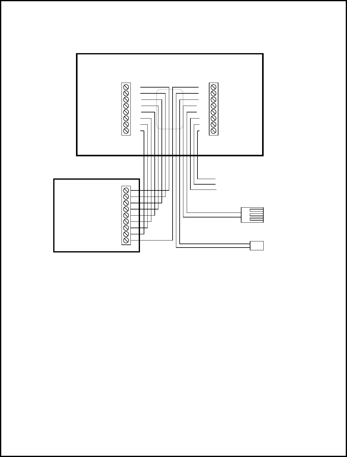
Wiring Diagrams
Standard Gas/Electric HVAC System
Standard HVAC System
Thermostat Connection
W1
1
R
W2
G
O/B
Y1
Y2
C
24VAC C
24VAC R
Heating stage 1
Heating stage 2
Changeover
Fan
Compressor Stage 1
Compressor Stage 2
PWM Fan Speed
Remote Temp Sensor
Outdoor Temp Sensor
Aux Relay NO
Aux Relay NC
Thermostat Back
Remote Indoor Sensor
RS
ODT
NO
ODT
C
NC
BK
RS
24VAC C
24VAC R
Heating stage 1 W1
Heating stage 2 W2
Fan G
Compressor Stage 1 Y1
Compressor Stage 2 Y2
Outdoor Temp Sensor
Remote Temp Sensor
Aux Relay Com
PWM Fan Speed BK
Aux Relay Outputs
Outdoor Temp Sensor
Normally Closed Contact
Normally Open Contact
Common
Wiring Diagrams
Heat Pump HVAC System
Heat Pump HVAC System
Thermostat Connection
W1
1
R
W2
G
O/B
Y1
Y2
C
24VAC C
24VAC R
Heating stage 1
Heating stage 2
Changeover
Fan
Compressor Stage 1
Compressor Stage 2
PWM Fan Speed
Remote Temp Sensor
Outdoor Temp Sensor
Aux Relay NO
Aux Relay NC
Thermostat Back
Remote Indoor Sensor
RS
ODT
NO
ODT
C
NC
BK
RS
24VAC C
24VAC R
Heating stage 1 W1
Heating stage 2 W2
Changeover O/B
Fan G
Compressor Stage 1 Y1
Compressor Stage 2 Y2
Outdoor Temp Sensor
Remote Temp Sensor
Aux Relay Com
PWM Fan Speed BK
Aux Relay Outputs
Outdoor Temp Sensor
Normally Closed Contact
Normally Open Contact
Common
Thermostat Setup
The thermostat must be set up to match the HVAC System type and configuration for proper operation.
Check the current configuration settings by pressing the Menu button to go to the Menu Selection Screen. Then select the
Thermostat Info menu item.
Thermostat Info Screen
Check the HVAC System Type and Fan Type info displayed.
If this matches the HVAC system, no further setup is required.
If not, press the Setup button to go the HVAC Mechanical settings menu.
Thermostat Setup
Select the settings to match the HVAC system:
1. HVAC system type: Gas/Electric or Heat Pump
2. Fan type (for gas/elec systems only): Gas or Electric
3. C/O (changeover valve – for Heat pump systems only) type: w/Cool or w/Heat
4. 2
nd
Stage Heat: N if no second stage, Y if yes.
5. Aux Heat (for Heat pump systems only): N if no Aux heat, Y if yes
6. 2
nd
Stage Cool: N if no second stage cooling, Y if yes
Done
Setup
TZ45H Ver: 1.02.02
ZVER: 02.16 ZNID: 000
ZHID: 00.00.00.00
System Type: Standard
Fan Type: Gas
Thermostat Info
Status
Press the Setup button to go to the HVAC System Mechanical Settings screen
Done
Type Gas/Elec
Fan Type Gas
C/O Type w/Cool
2
nd
Stage Heat N
Mechanical Settings
+
_

Advanced System Setup – Installer Settings
The TZ45H has advanced system setup options. These settings are accessed in the Installer Settings screen on the thermostat.
The Installer Settings is a hidden screen. To access it, press the MENU button to switch to the Menu Selection screen. Press and
hold the middle two buttons for 5 seconds to switch to the Installer Settings Screen.
Thermostat Main Menu
Installer Settings screen
Installer Settings Menu items
Display Lock Range: Y or N Default: N
Y = Display LOCKED
N = Display unlocked
Allows you to lock or unlock the thermostat buttons. When the buttons are locked, you can still access the main menu, but you will
not be allowed to select any menu options. The Installer Settings hidden button operation is always operational, allowing you to
return to this screen and turn Display Lock off.
Service Mode
Test Mode Range: Y or N Default: N
Y= Test mode on. Reduces all delays to 10 sec for quicker system testing
N= Test mode off. Normal system delays
CAUTION: in test mode all system safety delays are shorten. Do not operate the system compressor in test mode.
Disconnect Y1 or Y2 outputs if using test mode on a live system.
System Settings Submenu: Sets the HVAC operational settings below
Mechanical Settings Submenu: Sets HVAC system type and configuration
Type Range: Gas/Elec or Heat pump Default: Gas/Elec
Selects HVAC type, Gas/Electric or Heat pump
Fan Type Range: Gas or Elec Default: Gas
Selects the Fan type if system is Gas or Electric
C/O Type Range: w/Cool or w/Heat Default: w/Cool
Selects the Heat Pump Changeover Valve type
2
nd
Stage Heat Range: Y or N Default: N
Enables the 2
nd
Stage Heat operation
Aux Heat (HP) Range: Y or N Default: Y
Press and hold two middle buttons to enter the Installer Settings screen
Done
Select
User Settings
Away Setpoints
ZWave Install
Thermostat Info
Menu Selection
Done
Select
Display Lock N
Service Mode
System Settings
Max Heat SP 90
Installer Settings
+
_

Enables the Auxiliary Heat operation. Typically the Aux Heat will be heat-strips in a Heat Pump system
2
nd
Stage Cool Range: Y or N Default: N
Enables the 2
nd
Stage Cool operation
Schedule Enable Range: Y or N Default: N
When enabled, the local thermostats scheduler function is enabled.
Recovery Enable Range: Y or N Default: N
For Heat Pump Systems. Intelligent setback recovery is an automatic advance start of heating to allow the system to be at setpoint
by the schedule time, without the use of Aux heating.
Delta Settings : The Delta T Setting is the delta, or difference between, the setpoint and current temp for determining when a heat or
cool call comes on. The “delta” is the number of degrees away from setpoint.
H/C Delta Range: 3 - 15 degrees. Default: 3F (1C)
Sets the minimum separation between heating and cooling setpoints. Attempts to lower the cooling below the heating setpoint by
this amount will PUSH the heating setpoint down to maintain this separation. Same for setting the heating setpoint above the
cooling setpoint, it will PUSH the cooling setpoint up to maintain this separation.
Fan Purge Range: 0, 30 to 120 seconds Default: 0
Heating Delta Stage 1 ON Range: 1 to 8 degrees Default: 1
Sets the delta from setpoint that stage 1 heating starts.
Heating Delta Stage 1 OFF Range: 0 to 8 degrees Default: 0
Sets the delta from setpoint that stage 1 heating stops.
Stage 1 turns off at setpoint + Delta Stage 1.
Heating Delta Stage 2 ON Range: 1 to 8 degrees Default: 2
Sets the delta from setpoint that stage 2 heating starts.
Heating Delta Stage 2 OFF Range: 0 to 8 degrees Default: 0
Sets the delta from setpoint that stage 2 heating stops.
Stage 2 turns off at setpoint + Delta Stage 2.
Heating Delta Stage 3 ON Range: 1 to 8 degrees Default: 3
Sets the delta from setpoint that stage 3 heating starts.
Heating Delta Stage 3 OFF Range: 0 to 8 degrees Default: 0
Sets the delta from setpoint that stage 3 heating stops.
Stage 3 turns off at setpoint + Delta Stage 3.
Cooling Delta Stage 1 ON Range: 1 to 8 degrees Default: 1
Sets the delta from setpoint that stage 1 cooling starts.
Cooling Delta Stage 1 OFF Range: 0 to 8 degrees Default: 0
Sets the delta from setpoint that stage 1 Cooling stops.
Stage 1 turns off at setpoint - Delta Stage 1
Cooling Delta Stage 2 ON Range: 1 to 8 degrees Default: 2
Sets the delta from setpoint that stage 2 cooling starts.
Cooling Delta Stage 2 OFF Range: 0 to 8 degrees Default: 0
Sets the delta from setpoint that stage 2 Cooling stops.
Stage 2 turns off at setpoint -Delta Stage 2.
Max Heat SP Range: 40F to 109F (4C-43C) Default: 90F (32C)
Sets the maximum heating setpoint value. Will not ramp or accept setpoints higher that this maximum.
Min Cool SP Range: 44F to 113F (6C-45C) Default: 60F (15C)
Sets the minimum cooling setpoint value. Will not ramp or accept setpoints lower than this minimum.
Minimum Run Time (MRT) Range: 1- 9 Minutes Default: 3
Sets the minimum run time before a heating/cooling cycle can turn off.
Sets heating/cooling cycle time. Prevents rapid cycling.
Minimum Off Time (MOT) Range: 5-9 Minutes Default: 5
Sets the minimum off time before another heating/cooling cycle can begin. Provides compressor short cycle protection.
Fan Cycler
The fan cycler function cycles the HVAC system fan for an ON period followed by an Off period continuously. Used to provide
minimum air ventilation requirements. When the Fan ON time is set to a value greater than 0, an additional “Cycler” FAN mode is
present when pressing the FAN button.
Fan ON Time Range: 0-120 minutes Default: 0 (=OFF)
Fan OFF Time Range: 10-120 minutes Default: 10
Remote Sensors Submenu for Sensor Setup

RS1 Type Range: A curve, Type 2, Type 3 Default: Type 3
RS2 Type Range: A curve, Type 2, Type 3 Default: Type 3
RS2 Location Range: IN (indoors), OUT (outdoors) Default: IN
R1 Node ID ID for a Z-Wave remote sensor Default: 0
R2 Node ID ID for a Z-Wave remote sensor Default: 0
Humidity Settings: Submenu for humidity settings
RH Display Range: Off or On Default: On
Turns on or off the RH display on the main thermostat screen.
RH Setpoint Range: 20 to 80 in 5% steps Default: 55%
Sets the RH setpoint for Humidity control functions.
RH Setpoint Away Range: 20 to 80 in 5% steps Default: 65%
Sets the RH setpoint when in the AWAY mode.
RH Temp Delta Range: 1 to 5 deg Default: 2 deg
Sets the maximum overcooling temperature allowed for humidity control.
RH Setpoint Delta Range: 1 to 10 % Default: 5 %
Sets the % above the RH setpoint that the Humidity control will be activated.
RH On Time Range: 0 to 60 minutes Default: 30 min
Sets the maximum runtime for Humidity control to try to correct RH level.
RH Off Time Range: 0 to 60 minutes Default: 30 min
Sets the minimum off time for Humidity control after On time expires.
RH Off Delta Range: 0 to 10 % Default: 2%
Sets the % RH below the RH setpoint that the Humidity control will lower the room RH to before turning off.
Relay Setup (for aux relay A1 output)
A1 Relay mode Range: see below Default: Off
Off. No relay function
Humidify: Relay turns on when RH is below humidity setpoint
Dehumidify: Relay turns on when RH is above humidity setpoint
Net: Z-Wave commands turn Relay On and Off.
Configuration parameter #95 See Z-Wave Command Summary
Vent: Relay turns on when Vent is active.
DH-Fan: HVAC system fan speed control during dehumidification.
A1 Fan Interlock Range: Off, On Default: Off
Turns on fan output (G) when relay A1 is on
Restore Defaults Range: Yes, No Default: No
Restores all settings to factory defaults.
Press Yes to restore defaults
Press No to exit and not restore defaults

Model XR624
Operation Guide
XR624 Thermostat Screen
8$.5
88:88
AM
PM
Fan
$$$$$$$$$$$$$$$$$
Mon Tue Wed Thu Fri Sat Sun
Wake Day
Eve Night
Away Vac
Stg 234
Cooling
Heating
Yes
No
FC
Done
Menu
Sched
AwayBackVac
Off Next EM
Mode
CircSelectSCF
Save
HoldRunESM
CoolAutoHeat
On Auto On
88
5
HUMIDIFIER
SERVICE
FILTER
LOW BATT
Temporary
Override

Setting the System Mode
System Modes
Off: System is off. No heating or cooling will come on. If system was on, it will turn off immediately.
Heat: Only heating will occur.
Cool: Only cooling will occur.
Auto: Heating or cooling will come on according to the heating and cooling setpoints. The system will automatically
switch between heating and cooling modes as needed to maintain the setpoints.
Special Heat Pump Mode: Emergency Heat
Heat-E: An additional system mode, “Heat-E” for Emergency Heat will be displayed if the HVAC System Type is set to
Heat Pump. If there is a compressor failure with the Heat Pump system, setting the mode to Emergency Heat will allow
the supplemental Aux Heat to come on first whenever there is a call for heating. It also disables the compressor output to
prevent further damage to the HVAC system.
Caution! Emergency Heat should only be used for emergencies until the HVAC system can be repaired. Running the system in
Emergency Heat mode is commonly the most expensive mode since only the electric heat strips are being used instead of
the more efficient heat pump compressor.
Press MODE button to
change system mode
75
1135
AM
Fan
F
Menu
Sched
Mode
Run
Auto
Auto
70

Setting the Heating or Cooling Temperature Setpoint
Setpoint Change
To change the setpoint, press the Up or Down arrow buttons. The screen will switch to the setpoint change screen (as above) and
show the current setpoint of the current heating or cooling mode. Adjust setpoint temperature up or down with the arrow buttons.
Note! When in the Setpoint Change screen, pressing the MODE button will switch the setpoint being displayed between
the Heat and Cool setpoints.
Setpoint Push: The cooling setpoint cannot be set below the heating setpoint. The thermostat will “push” the heating setpoint
lower if the cooling setpoint is set below the current heating setpoint. A 3 degree separation is maintained between the heating and
cooling setpoints. The same is true for raising the heating setpoint above the cooling setpoint. The thermostat will “push” the
cooling setpoint up to maintain the 3 degree separation.
Press Up/Down
arrow buttons
to change setpoint
75
1135
AM
Fan
F
Menu
Sched
Mode
Run
Auto
Auto
70

Setting the Fan Mode
Fan Modes:
Auto: Fan automatically operated by the HVAC system. (normal setting)
On: Manual Fan mode. Fan stays on until mode is changed back to Auto,
independent of the heating or cooling system operation.
Press the FAN button to
change the fan mode
75
1135
AM
Fan
F
Menu
Sched
Mode
Run
Auto
Auto
70

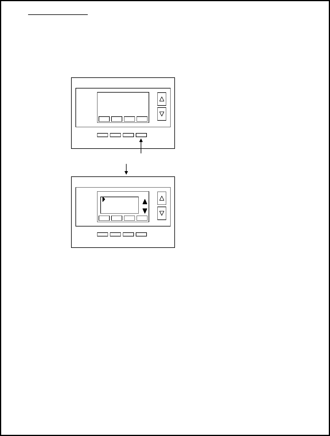
Thermostat Menu Mode
The Thermostat has a menu of setup and information displays.
To change to the Menu Mode, press the Mode button
The display will change to the Menu Mode and display the Setup screen.
Use the Up/Down arrow buttons to scroll through other menu items.
Menu Mode options
SETUP User preference settings
SYSTEM Thermostat HVAC system settings
ZWAVE Z-Wave network install or remove
CLOCK Setting the thermostat time and day
INFO Displays thermostat version and setup info
SETUP Menu
User preference settings.
FAHRENHEIT OR CELSIUS. Select the temperature display mode.
BACKLIGHT TIMEOUT. Sets the time from last button press that the backlight will turn off. Range:10-30 seconds. Note: long
backlight timeouts will reduce battery life.
If the thermostat is powered from 24VAC, the backlight timeout can be set to “0” which will keep the backlight on continuously.
SENSOR CALIBRATION Change the temperature calibration by +/- 7 degrees.
Use the Up/Dn arrow buttons to change to the desired display temperature.
SYSTEM Menu
SYSTEM TYPE. Select the system type, STANDARD or HEAT PUMP
FAN TYPE (Standard systems only).
Select fan type: GAS (typical default setting) or ELECTRIC
CHANGE OVER TYPE (Heat Pump systems only).
Select the Changeover type:
Changeover WITH COOL (typical default setting)
Changeover WITH HEAT
See Installation Guide for more information on System setup and the Advanced Systems Menu
Press the Menu button to go
to the Menu mode
75
1135
AM
Fan
F
Menu
Sched
Mode
Run
Auto
Auto
70

Z-WAVE Menu
This menu item allows the thermostat to be installed or uninstalled from a Z-Wave network. Follow the instructions in the Z-Wave
Installation section.
INSTALL Press to install the thermostat, if not already installed in a Z-Wave Network (when a controller is in install mode)
REMOVE Press to remove the thermostat from a Z-Wave Network
CLOCK Menu
Set the time and day of the week.
Press select to set the DAY. The current day of the week setting will be displayed.
Press the UP/DN arrows to change the day of the week desired.
Press select to set the TIME. The current time will be displayed.
Press the UP/DN arrows to change the time.
INFO Menu
The INFO menu displays information about the thermostat. Use the Up/Dn buttons to scroll through the various items.
Thermostat information displayed:
VERSION Thermostat firmware version
ZWAVE Z-Wave firmware version
NODE ID Z-Wave Node ID
HOME ID Z-Wave Home ID
SYSTEM TYPE displays current System Type setting
If System Type = Standard
FAN TYPE displays current Fan Type setting
If System Type = Heat Pump
CHANGEOVER TYPE displays current Change Over setting
Thermostat Operation
Minimum Run Time (MRT)
The thermostat has a Minimum Run Time (MRT) delay after the start of any heating or cooling call. This minimum run time assures
even heating and cooling cycles. The MRT will keep the system on, even if it reaches the setpoint room temperature, or you change
the setpoint to a temperature that would satisfy the call, until the MRT expires. Changing the Mode to OFF will cancel the MRT and
the system will turn off immediately. The MRT can be adjusted in the Advanced Settings menu of the thermostat.
Note: The MRT status is shown in the thermostat Status display.
Minimum Off Time (MOT)
The thermostat has a Minimum Off Time (MOT) delay after any heating or cooling cycle ends. This delay prevents rapid
heating/cooling cycles and also provides “short cycle protection” for the system compressor. This delay may be noticeable when
you change a setpoint and it does not respond immediately due to the MOT delay timer preventing the system from restarting. The
MOT delay time can be adjusted in the Advanced Settings menu of the thermostat but there is a minimum of 5 minutes delay to
assure compressor protection.
Note: The MOT status is shown in the thermostat Status display.

Z-Wave® Operation
The XR624 is based on the Slave Library in the Z-Wave Ecosystem.
Z-Wave controllers from various manufacturers support the Z-Wave process of adding or removing a device from a network. The
thermostat is a Z-Wave Slave and a Z-Wave controller is required as the primary controller to setup and maintain the network.
The following procedure will allow the thermostat to be installed (inclusion) or removed (exclusion) from a Z-Wave network.
NOTE: If the thermostat is installed in a network while running on batteries, it will be installed as a FLiRs Z-Wave type of device.
This is a power saving mode that converses the batteries by keeping the radio asleep most of the time. However, in this mode, the
thermostat does not act as a router node in the Z-Wave network.
If the THERMOSTAT is installed in a network while powered by 24VAC, it will be installed as an always-listening device and can act
as a router node in the Z-Wave network.
Caution! Once installed in a Z-Wave network, if you change how the thermostat is powered (from batteries to 24VAC or
vice versa), you must remove and re-install the thermostat in the Z-Wave network for it to work correctly.
Before installing the thermostat into a Z-Wave Network, check that is not already installed in a network by viewing the Home and
Zone ID’s located in the INFO screen. An un-installed thermostat will show a Node ID of 0. Consult your controller’s user manual
for details on removing a device from a Z-Wave network.
Inclusion: Installing the thermostat into an existing Z-Wave network
1. Set your primary controller to Install or Include mode, to add the THERMOSTAT as a node on your network (see your
controller’s user manual for detailed instructions).
2. Press the FAN button and hold until the screen changes to the Menu screen.
3. Press the UP button until ZWAVE is shown in the Status Display line then press Select.
4. INSTALL should be shown on the status line. Press Select to install in the network. The status line will show the
progress as the THERMOSTAT is added into the network. Wait until SUCCESS or FAILED is shown on the status
display.
5. Press Done to exit the ZWAVE screen.
6. Press Done again to exit the Menu screen.
7. The Radio Icon should be shown in the Thermostat Main screen indicating the thermostat is enrolled into a network.
Your controller will indicate the thermostat was successfully added to its network (see your controller’s user manual for details).
Also you can check if the thermostat was successfully added to the network by checking the Node ID and Home ID in the INFO
screen.
Z-Wave Network Note: Inclusion and exclusion are always done at normal transmit power mode.
Network Wide Inclusion
If your controller supports Network Wide Inclusion (NWI), then you can optionally set the primary to NWI include mode.
Please note that NWI inclusion mode does not end when you have included a new node. This allows multiple nodes to be
included without having to physically go back to the controller to initiate the next inclusion. Therefore you must manually
terminate NWI inclusion mode at the controller when you have finished including any new nodes to the network. Since
intermediate included nodes will assist the inclusion process by routing messages, we recommend that nodes close to the
primary controller be installed first, proceeding out in consecutive rings from the controller.
Exclusion: Removing the thermostat from a Z-Wave network
1. Set your primary controller to Uninstall or Remove mode to remove the thermostat as a node on your network (see your
controller’s user manual for detailed instructions).
2. Press the FAN button and hold until the screen changes to the Menu screen.
3. Press the UP button until ZWAVE is shown on the status line then press Select.
4. REMOVE should be displayed. Press Select to remove from the network. The status display will show the progress as
the thermostat has been removed from a network. Wait until SUCCESS or FAILED is shown on the status line.
5. The controller will indicate the thermostat has been removed from the network.
6. The Radio Icon will disappear from the Thermostat Main screen.
Note: You can confirm the thermostat has been removed by checking that the Node ID is 0 in the INFO screen.

FCC/IC
INFORMATION TO USER
This device complies with Part 15 of the FCC Rules. Operation is subject to the following two conditions: (1) This device may not
cause harmful interference, and (2) This device must accept any interference received, including interference that may cause
undesired operation.
This equipment has been tested and found to comply with the limits for Class B Digital Device, pursuant to Part 15 of the FCC
Rules. These limits are designed to provide reasonable protection against harmful interference in a residential installation. This
equipment generates and can radiate radio frequency energy and, if not installed and used in accordance with the instructions, may
cause harmful interference to radio communications. However, there is no guarantee that interference will not occur in a particular
installation. If this equipment does cause harmful interference to radio or television reception, which can be determined by turning
the equipment off and on, the user is encouraged to try to correct the interference by one or more of the following measures.
Reorient or relocate the receiving antenna
Increase the separation between the equipment and receiver
Connect the equipment into an outlet on a circuit different from that to which the receiver is connected
Consult the dealer or an experienced radio/TV technician for help
Any changes or modifications not expressly approved by the party responsible for compliance could void the user’s authority to
operate the equipment.
This device complies with Industry Canada license-exempt RSS standard(s). Operation is subject to the following two conditions: (1)
this device may not cause interference, and (2) this device must accept any interference, including interference that may cause
undesired operation of the device.
This Class B digital apparatus complies with Canadian ICES-003.
Cet appareil numérique de la classe[B est conforme à la norme NMB-003 du Canada.
Le présent appareil est conforme aux CNR d'Industrie Canada applicables aux appareils radio exempts de licence. L'exploitation est
autorisée aux deux conditions suivantes : (1) l'appareil ne doit pas produire de brouillage, et (2) l'utilisateur de l'appareil doit
accepter tout brouillage radioélectrique subi, même si le brouillage est susceptible d'en
compromettre le fonctionnement.
