William J. Hughes Technical Center
Verification Requirements Traceability
Matrix (VRTM)
Content and Format Guidance
Document # VVSPT-E5-GDE-017
Version # 3.0
Version Date November 20, 2018
FAA WILLIAM J. HUGHES TECHNICAL CENTER
ATLANTIC CITY INTERNATIONAL AIRPORT, NEW JERSEY 08405

VVSPT-E5-GDE-017 V3.0 ii 11/20/2018
Document Version Control
Version Description Of Change Date
1.0 Final 08/13/2008
2.0 508 Formatting 09/17/2016
2.1 Revising to match terminology of T&E
Handbook (RLB)
6/25/2018
2.2 Release for Peer Review 09/06/2018
2.3 Revised as of comments from Peer Review 10/15/2018
2.4 Revised as of ANG-E5A comments 11/13/2018
2.5 Revised as of Technical Editor updates 11/16/2018
3.0 Final 11/20/2018

VVSPT-E5-GDE-017 V3.0 iii 11/20/2018
CONTENTS
1 INTRODUCTION ................................................................................................................... 1
1.1 DEFINITION AND PURPOSE ....................................................................................... 1
1.2 BACKGROUND .............................................................................................................. 1
1.3 SCOPE ............................................................................................................................. 1
1.4 OVERVIEW OF THE TEMP VRTM ............................................................................. 2
1.5 OVERVIEW OF THE DT VRTM ................................................................................... 2
1.6 OVERVIEW OF THE OT VRTM ................................................................................... 3
1.7 RELATIONSHIPS AMONG THE VRTMS ................................................................... 4
1.8 REFERENCE DOCUMENTS ......................................................................................... 8
1.9 FAA DATABASE CONSIDERATIONS ........................................................................ 8
2 DETAILED TEMP VRTM CONTENT AND FORMAT ...................................................... 9
2.1 CONTENT OF THE TEMP VRTM ................................................................................ 9
2.2 FORMAT OF THE TEMP VRTM ................................................................................ 10
3 DETAILED DT VRTM CONTENT AND FORMAT.......................................................... 12
3.1 CONTENT OF THE DT VRTM ................................................................................... 12
3.2 FORMAT OF THE DT VRTM ..................................................................................... 14
4 DETAILED OT VRTM CONTENT AND FORMAT.......................................................... 17
4.1 CONTENT OF THE OT VRTM ................................................................................... 17
4.2 FORMAT OF THE OT VRTM ..................................................................................... 19
5 GLOSSARY .......................................................................................................................... 23
6 ACRONYM LISTING .......................................................................................................... 25

VVSPT-E5-GDE-017 V3.0 iv 11/20/2018
Intentionally Blank

VVSPT-E5-GDE-017 V3.0 1 11/20/2018
1 INTRODUCTION
1.1 DEFINITION AND PURPOSE
The Federal Aviation Administration (FAA) Systems Engineering Manual defines Verification
Requirements Traceability Matrix (VRTM) as a “matrix correlating requirements and the
associated verification method(s). The VRTM defines how each requirement (functional,
performance, and design) is to be verified, the stage in which verification is to occur, and the
applicable verification method levels.” The VRTM provides the ability to trace a lower-level
requirement back to its source, or “parent requirement,” and to maintain status of requirement
verification.
1.2 BACKGROUND
The Program Requirements Document (PRD) contains all requirements for a program, whether
they will be satisfied by a product development, by procedure changes, or by changes to external
systems that may be in control of stakeholders other than the FAA. The PRD has each program’s
set of Critical Operational Issues (COIs), as well as the uniquely identified requirements which
trace to the National Airspace System (NAS)-Requirements Document (RD), some of which are
identified as Critical Performance Requirements (CPRs). The traceability matrix in the PRD is
required to trace each requirement from the PRD back to “one or more enterprise level
requirements listed in the NAS-RD,” and “to a function in the Functional Analysis Document.”
(See Program Requirements Template for AMS Acquisitions for further detail). Please note this
process will not be applicable for mission support programs.
The Test and Evaluation (T&E) Handbook, included as Guidance in the Acquisition Management
System (AMS) for test teams, stipulates three types of VRTMs: The Test and Evaluation Master
Plan (TEMP) VRTM, the Development Test (DT) VRTM and the Operational Test (OT) VRTM.
1.3 SCOPE
The scope of this guidance is limited to the following VRTM templates:
a) TEMP VRTM
b) DT VRTM
c) OT VRTM
This guidance will discuss the relationships of the three VRTMs above to other traceability
matrices that are required to be in the following documents:
a) PRD
b) System Specification Document (SSD), provided by FAA to developer.
c) System/Subsystem Specification (SSS), provided by developer.
Details of requirements for the PRD, SSD and SSS may be found in the references cited in section
1.8.

VVSPT-E5-GDE-017 V3.0 2 11/20/2018
1.4 OVERVIEW OF THE TEMP VRTM
The TEMP VRTM shows coverage of all PRD requirements within the scope of the test program.
The TEMP VRTM is used to manage and plan the test program, allocating requirements to either
the DT phase, the OT phase, or both. (See the TEMP Template for New Investments).
The TEMP provides the initial decomposition of COIs. COIs are decomposed in the TEMP by:
a) Decomposing COIs into Measures of Effectiveness (MOEs) and Measures of
Suitability (MOSs):
MOEs and MOSs are qualitative decompositions of the COI which must be measured
to fully determine whether a COI has been satisfied.
b) Further decomposing MOEs and MOSs into Measures of Performance (MOPs):
MOPs are measurable, quantitative/qualitative values that characterize and support the
evaluation of the COIs, MOEs and MOSs. Decomposition is preliminary during TEMP
development, with final decomposition occurring in the OT Plan.
c) Mapping MOEs and MOSs to PRD requirements in the VRTM:
As MOPs are developed by a test team, they must not conflict with the PRD or SSD.
PRD requirements, including CPRs, and the SSD requirements may serve as MOPs. If
a conflict is discovered between the PRD and any MOEs, MOSs or MOPs the conflict
must be resolved.
Further information on the COI Decomposition process can be found in the COI Decomposition
Guide located on the Verification & Validations (V&V) Repository in the ANG-E T&E Portal.
The COI decomposition is documented in Appendix A of the test program’s TEMP.
The TEMP VRTM is documented in Appendix B of the test program’s TEMP. This VRTM is
indexed by the numbered requirements of the PRD. The VRTM associates each numbered
requirement MOEs, MOSs and MOPs under specific COIs as documented in Appendix A. The
TEMP VRTM also provide a cross reference of program requirements and CPRs to the respective
test phase(s) and test activities in which the MOEs/MOSs/MOPs are addressed.
1.5 OVERVIEW OF THE DT VRTM
The developer is responsible for creating and maintaining the DT VRTM, which is used as a
framework for DT testing. For those requirements in the PRD that will be addressed by a system
development, FAA creates an SSD describing what must be developed to meet PRD requirements.
The SSD traces requirements back to the PRD (see FAA-STD-067, Preparation of Specifications).
Developers, (usually after a contract award), deliver a more detailed functional specification, the
SSS, to meet the SSD requirements. The DT VRTM uses the requirement identifiers in the
developer’s SSS, which provides traceability back to the SSD in accordance with the Data Item
Description (DID) in the contract. The unique identifiers used by the developer in the SSS for
requirements, or their child requirements, usually serve as the primary index for traceability in the
SSS. The DT VRTM must be included in the Contractor’s Master Test Plan (CMTP), lower-level
DT plans, procedures documents, and reports, with additional columns completed to trace program
requirements to specific documented test procedures, and to test results.

VVSPT-E5-GDE-017 V3.0 3 11/20/2018
The developer might go through a process of requirement definition and an interpretation of the
SSD requirements to develop and deliver the SSS while is developing a DT VRTM. As a result,
there is a possibility that the developer will revise the DT VRTM multiple times.
1.6 OVERVIEW OF THE OT VRTM
The OT VRTM traces COIs, and their constituent MOEs, MOSs, and MOPs to the test activities
and test cases. It also identifies requirements from the PRD (including CPRs), and the SSD that
relate to each COI/MOE/MOS/MOP. The OT VRTM may be revised as OT matures through
procedure development and test conduct. During OT reporting, the test case information such as
run dates and results, will be entered into the VRTM. The completed VRTM will be contained in
the OT test reports.

VVSPT-E5-GDE-017 V3.0 4 11/20/2018
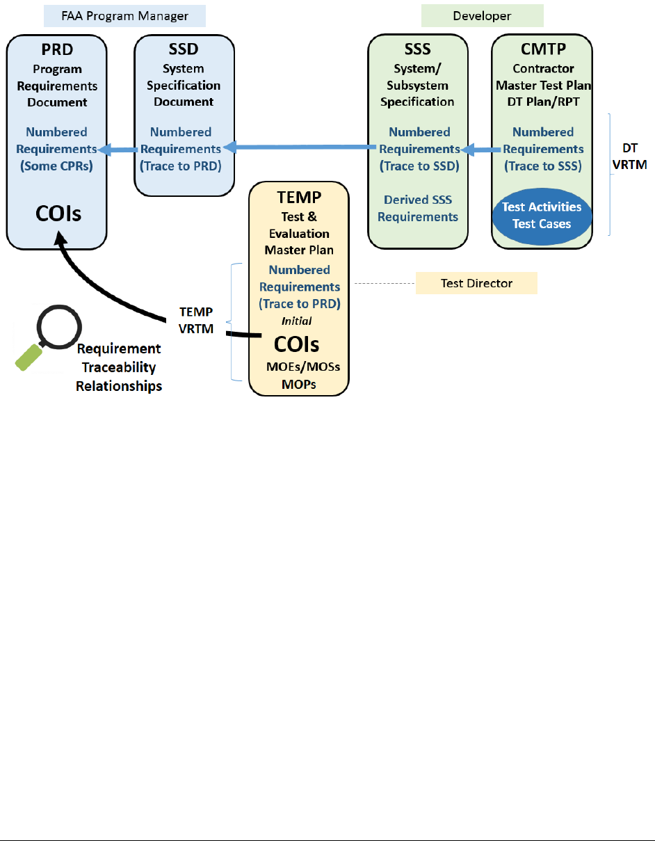
1.7 RELATIONSHIPS AMONG THE VRTMS
The following diagrams indicate the traceability of requirements from the lowest level for a
program, the DT and OT VRTMs, up to the highest level for a program, the PRD.
The first step in program traceability development is to link the requirements in the SSD to the
PRD, as illustrated in Figure 1-1. This is the responsibility of the FAA Program Manager, and is
required before Final Investment Decision (FID).
Figure 1-1 – Traceability Between PRD and SSD

VVSPT-E5-GDE-017 V3.0 5 11/20/2018
The Program’s Test Director (or Test Directors if there are more than one), develops the TEMP
which traces the PRD requirements applicable to the test program to a phase of testing (usually
DT or OT). The TEMP also includes the initial decomposition of COIs into MOEs, MOSs and
MOPs, as illustrated in Figure 1-2.
Figure 1-2 – Traceability Between PRD and TEMP
VVSPT-E5-GDE-017 V3.0 6 11/20/2018
The developer is responsible for preparing the SSS, which is the basis for the development of the
new system. The DT VRTM in the CMTP maps the SSS requirements to Test Activities and Test
Cases, as illustrated in Figure 1-3. The SSS shows traceability back to the SSD. This traceability
supports mapping from low-level activities during DT back to the PRD and the CPRs.
Figure 1-3 – Traceability Between PRD and DT Documents

VVSPT-E5-GDE-017 V3.0 7 11/20/2018
OT planning further refines and matures the original decomposition of the COIs, MOEs, MOSs
and MOPs documented in the TEMP and associates test activities and test cases back to the COIs
in the OT VRTM. As illustrated in Figure 1-4, the OT VRTM also maintains traceability back to
the SSD and PRD requirements. This diagram therefore illustrates the full traceability of all test
activities back to the PRD, from both DT and OT.
It’s recommended that Test Directors have a forward looking prospective on the traceability of the
PRD and the SSD requirements such that traceability to the SSS is achieved as the process through
development into DT and OT.
Figure 1-4 – Traceability Among Requirements Documents, Test Activities and Test Cases

VVSPT-E5-GDE-017 V3.0 8 11/20/2018
1.8 REFERENCE DOCUMENTS
a) COI Decomposition Guide, version 1, FAA Air Traffic Organization NextGen and
Operations Planning Services, TSPAT-D3-GDE-001, November 2008
b) DI-IPSC-81431A, System/Subsystem Specification (SSS), Data Item Description,
(Sample), FAA AMS, January 10, 2000. http://fast.faa.gov/docs/sowgen_docs/dids/DI-
IPSC-81431A.doc
c) FAA System Engineering Manual, v1.1, Air Traffic Organization Operations Planning,
Washington, DC, September 11, 2015. https://sep.faa.gov/file/get/2974
d) FAA-STD-067, Preparation of Specifications, FAA, December 4, 2009.
https://f10011.eos-intl.net/F10011/OPAC/Details/Record.aspx?BibCode=30738591
e) Program Requirements Template for AMS Acquisitions, Version 2.2, July 2017, FAA
Offices: ANG-B, ANG-B1, ADE-200. http://fast.faa.gov/docs/programreq.docx
f) Test and Evaluation Handbook, Version 4.0, FAA William J. Hughes Technical Center,
VVSPT-A2-PDD-013, May 2017.
g) Test and Evaluation Master Plan Template for New Investments, Version 5.0, FAA
William J. Hughes Technical Center, VVSPT-D4-TEM-012, July 2015.
h) Test and Evaluation OT Test Plan Template, FAA William J. Hughes Technical Center,
Version 3.0, VVSPT-D4-TEM-017, October 2011
1.9 FAA DATABASE CONSIDERATIONS
For full traceability, the FAA Dynamic Object Oriented Requirements System (DOORS) database
should make use of all fields in the TEMP, DT, and OT VRTMs. With this full traceability, System
Engineering would have insight into the test program on requirement status. The test program
would be able to use the FAA DOORS database to generate and manage the VRTMs.

VVSPT-E5-GDE-017 V3.0 9 11/20/2018
2 DETAILED TEMP VRTM CONTENT AND FORMAT
2.1 CONTENT OF THE TEMP VRTM
Table 2-1 briefly describes the content for each column of the TEMP VRTM. Table 2-3 provides
an example of the TEMP VRTM. Detailed format for each column is provided in the next section.
Each VRTM reflects modification date information in the title.
Each VRTM reflects preparation and modification date information.
Table 2-1 – Brief Description of TEMP VRTM Columns
Column Title Content
PRD ID
A unique identifier from the PRD.
REQ TEXT
The text of the requirement from the PRD.
CPR (N/A or #)
Whether the requirement has been identified as a CPR, which
may be referenced by its additional CPR number in Appendix
1 of the PRD.
TEST PHASE
Identification of the T&E Phases, which will verify the
requirement.
VERIF METH
Identification of the Verification Method to be used for in
each phase.
MOE /MOS #*
Identification of any measures under a related COI for this
requirement.
MOE / MOS
TEXT*
The text of the measure identified in the sixth column.
MOP #*
The ID of related MOPs for the requirement.
The TEMP VRTM can optionally contain additional columns such as the named T&E Activity
within the phase and the Success Criteria, but these may not be known, until the later phases of
planning.
*Note: Programs might use a separate spreadsheet to decompose COIs to MOEs, MOSs and
MOPs

VVSPT-E5-GDE-017 V3.0 10 11/20/2018
2.2 FORMAT OF THE TEMP VRTM
For each column in the TEMP VRTM, Table 2-2, below has a row, which describes the format for
the column’s entry.
Table 2-2 – Format of TEMP VRTM Columns
Field/Column /
Attribute
Description Example Values
PRD ID
The requirement identifier
from the PRD
PRD-515
PRD-2112
REQ TEXT
The full text of the
requirement from the source
document.
The system shall be
designed using …
----
Does the SYSTEM
provide the ability
to…?
CPR (N/A or #)
If this TEMP item is a CPR,
or child requirement of a
CPR, the number from the
CPR table in the PRD goes
here, otherwise, put “N/A.”
N/A
4
TEST PHASE
The T&E phase in which the
requirement will be verified.
DT, OT
VERIF METH
The method that will be used
for verification of the
requirement. Usually either
Analysis, Demonstration,
Inspection, or Test.
A,
D,
I,
T
MOE /MOS #
Measures under related COIs
in which the requirement will
be verified.
MOE 1.3
MOS 9.1
MOE / MOS
TEXT
The text of the related MOE,
or MOS.
SYSX automatically
provides Terminal data
received from…
MOP #
ID of related MOP.
MOP 1.3.2

VVSPT-E5-GDE-017 V3.0 11 11/20/2018
Table 2-3 – Example of TEMP VRTM
TEMP VRTM FOR [PROGRAM] – modified [Date]
PRD ID REQ TEXT
CPR
(N/A
or #)
TEST
PHASE
VERIF
METH
MOE /
MOS #
MOE / MOS TEXT
MOP #
PRD-0128 SYSX shall provide the latest
Terminal data automatically in
accordance with registered
parameters.
3
3
3
DT D N/A N/A N/A
OT T MOE
1.3
SYSX automatically provides
Terminal data received from RVR
to NEMS in accordance with the
NEMS Asynchronous Messaging
ICD.
MOP 1.3.1
MOP 1.3.2
MOP 1.3.3
OT D MOS
1.4
SYSX automatically provides
Terminal data received from ASDE-
X to NEMS in accordance with the
NEMS Asynchronous Messaging
ICD.
N/A
PRD-0154 Data communications training
systems must simulate data
communications operator
position functionality at
operator positions.
N/A OT D MOS
9.1
Training enables Tech Ops
personnel to maintain Data
Comm operations.
MOP 9.1.1
MOP 9.1.2
PRD-0201 The system shall have a
response time from user input
to system output in accordance
with the NAS-RD-2013.
5
5
5
DT T, A N/A N/A N/A
OT D
MOE
4.1
The system allows the sending
user to designate the type of
response required
MOP 4.1.1
MOP 4.1.2
OT T
MOS
4.2
The system displays user response
to an electronic message.
N/A

VVSPT-E5-GDE-017 V3.0 12 11/20/2018
3 DETAILED DT VRTM CONTENT AND FORMAT
The DT VRTM lists all of the requirements that must be met by the system to satisfy the functional
and performance requirements in the program’s SSS. As described in the DT overview (Section
1.5) the SSS requirements must trace to the SSD.
The following table describes the required fields/columns of the DT VRTM. The DT VRTM is
under the control of the developer. The government stipulates required content and format to a
prime contractor in the DIDs for deliverables that include DT VRTMs.
3.1 CONTENT OF THE DT VRTM
Table 3-1 briefly describes the content for each column of the DT VRTM. Table 3-3 provides an
example of the DT VRTM. Detailed format for each column is provided in the next section. Each
VRTM reflects modification date information in the title.
Table 3-1 – Brief Description of the DT VRTM Columns
Column Title Content
SSS ID
A unique identifier that will allow unambiguous reference to the requirement
in each row of this DT VRTM. The developer may use a proprietary format
from the SSS.
REQ TEXT
The text of the requirement, including section number.
REQ/PARENT
TRACE
The immediate source of the requirement (“Parent Requirement”), which
would usually be from the SSD, but sometimes comes from the SSS for a
“child” or derived requirement.
PRD TRACE
The requirement identifier from the PRD that the requirement traces to,
usually indirectly through the SSS, and SSD.
CPR (N/A OR #)
Whether the requirement has been identified as a CPR, which may be
referenced by its CPR number from Appendix 1 of the PRD.
ACTIVITY ID
Identification of the DT Activity, or Activities in which the requirement will
be verified. This column may have multiple entries, in “sub-
rows,” for
multiple Activities that verify the requirement, such as FAT, SAT, etc.
TEST CASE ID
The identifier for the specific test case(s) associated with the activity, which
will verify the requirement.
VERIF
METHOD
Identification of the Verification Method for each DT test case identified.
RUN DATE
Either the planned or the actual date for the test case execution.
TEST RESULT
The result of the test case. Pass, Fail, Partial

VVSPT-E5-GDE-017 V3.0 13 11/20/2018
The Test Case ID column of the DT VRTM can optionally be expanded into multiple columns,
such as those described in the T&E Handbook (i.e., Test Case Group, Test Case, Step), but DT test
case structure would be defined by the developer. As development matures, columns such as
Success Criteria may be added.

VVSPT-E5-GDE-017 V3.0 14 11/20/2018
3.2 FORMAT OF THE DT VRTM
For each column of the DT VRTM, Table 3-2 below has a row which describes the format for the
column’s entry.
Table 3-2 – Format of DT VRTM Columns
Column (or
Attribute)
Type Description Example Values Target
Document
SSS ID
Text
The requirement number from the
System/Segment Specification
(SSS, or “B-level Spec”), usually
provided by the developer
Proprietary format
SSS-736
SSS-12953
DT Plan
REQ TEXT
Text
The full text of the requirement
from the source document.
The SYSTEM must
enable all
SYSTEM Services
identified in Table
3-1 …
DT Plan
REQ/PARENT
TRACE
Text
The requirement number of the
System Specification Document
(SSD, or “A-level Spec”), that
this requirement traces back to,
and if there is an applicable
parent SSS ID #
SSD-10864
SSS-3 [new child]
DT Plan
PRD TRACE
Text
The parent PRD requirement that
was the indirect source for this
DT VRTM item. This
information should be carried
forward in the System
Specification Document (SSD), to
the System/Segment Specification
(SSS)
PRD-380
DT Plan
CPR (N/A OR #)
Text
If this DT VRTM item is a CPR,
or child requirement of a CPR,
the number from the CPR table in
the PRD goes here, otherwise, put
“N/A.”
N/A
4
DT Plan

VVSPT-E5-GDE-017 V3.0 15 11/20/2018
Column (or
Attribute)
Type Description Example Values Target
Document
ACTIVITY ID
Text
The name of the test series in the
DT program where the
requirement will be tested. This
column may have multiple
entries, in “sub-rows,” for
multiple Activities that verify the
requirement, such as FAT, SAT,
etc. The remaining columns
would likewise need to have
multiple corresponding entries.
Factory Acceptance
Testing,
Site Acceptance
Testing
DT Plan
TEST CASE ID
Text
The developer’s identifier for the
procedures that will be executed
to verify the requirement.
Proprietary format.
DT Procedures
VERIF
METHOD
Text
The method(s) that will be used
for verification of the
requirement. Usually either
Analysis, Demonstration,
Inspection, or Test.
A
I
T
D
A/D
T/A
DT Plan
RUN DATE
Date
The proposed or actual date the
test case was executed
Any common date
formats.
DT Report
TEST RESULT
Text
The result of test case execution.
Unverified, Pass,
Fail, Partial,
Deferred
DT Report

VVSPT-E5-GDE-017 V3.0 16 11/20/2018
Table 3-3 – Example of DT VRTM
DT VRTM FOR [PROGRAM] – modified [Date]
* Indicates a Parent where verification occurs at the Child level
SSS
ID
REQ
TEXT
REQ/PARENT
TRACE
PRD
TRACE
CPR
(N/A
OR #)
ACTIVITY
ID
TEST
CASE
ID
VERIF
METHOD
RUN
DATE
TEST
RESULT
SSS-
11
3.1 The
SYSTEM
must enable
all
SYSTEM
Services
identified in
Table 3-1 …
SSD-111
PRD-
379
7
7
7
FAT 4.5.6 T 01/19/2018 Pass
I & I 4.5.7 T 03/20/2018 Pass
SAT 4.5.8 D, A 05/20/2018 Pass
SSS-
12
3.2 The
SYSTEM
must disable
individual
SYSTEM
Services …
SSD-112
PRD-
380
N/A
FAT 2.2.1 D 01/22/2018 Fail
SSS-
34
4.1 The
system shall
provide a
subset of the
SYSB
services to
…
SSD-7
PRD-
997
2
* * * * Partial
SSS-
841
4.2.1 The AI
Service
Engine shall
provide
access to
web
services
only to
consumers
on-ramped
to
SYSTEM2.
SSD-7/
SSS-34
PRD-
997
2
2
FAT 3.4.1 T, A 01/20/2018 Fail
SAT 3.4.2 D 05/20/2018 Pass

VVSPT-E5-GDE-017 V3.0 17 11/20/2018
4 DETAILED OT VRTM CONTENT AND FORMAT
The OT VRTM contains the final decomposition of the COIs from the TEMP allocated to OT
Activities.
The following table describes the required fields/columns of the OT VRTM. The OT VRTM is
under the control of the government Test Director.
4.1 CONTENT OF THE OT VRTM
Table 4-1 briefly describes the content for each column of the OT VRTM. Table 4-3 provides an
example of the OT VRTM. Detailed format for each column is provided in the next section. Each
VRTM reflects modification date information in the title.
Table 4-1 – Brief Description of the OT VRTM Column
Column Title Content
COI/MOE/MOS/MOP
ID
A unique identifier that will allow unambiguous reference to the
entry in each row of this OT VRTM.
COI/MOE/MOS/MOP
TEXT
The text of the COI/MOE/MOS/MOP.
RELATED PRD
REQS
Indication of which requirements in the PRD, are related to this
COI, MOE, MOS, or MOP.
PRD TEXT The full text of the requirement from the PRD document.
RELATED SSD
REQS
Indication of which requirements in the SSD, are related to this
COI, MOE, MOS, or MOP.
CPR (N/A OR #)
Whether any of the related requirements have been identified as
CPRs, which may be referenced by the CPR numbers from
Appendix 1 of the PRD.
ACTIVITY #2
ACTIVITY ID
The OT Activity, or Activities in which the MOE/MOS/MOP will
be verified. This column may have multiple entries, in "sub-rows,"
for multiple Activities that verify the item, such as Integration
Testing, Operational Effectiveness and Operational Suitability
Testing (OE/OS), etc.
TEST CASE ID
The identifier for the specific test case(s) associated with the Test
activity.
VERIF METHOD The Verification Method for each OT test case identified.
RUN DATE Either the planned or actual date for the test case execution.
TEST RESULT
The result of the test case’s execution. Pass, Fail, Partial, Limited
As the program matures, additional OT VRTM columns, such as Success Criteria, maybe added.

VVSPT-E5-GDE-017 V3.0 18 11/20/2018
The Test Case ID column of the OT VRTM can optionally be expanded into multiple columns,
such as those described in the T&E Handbook and the T&E OT Test Plan Template (i.e., Test Case
Group, Test Case and Step).

VVSPT-E5-GDE-017 V3.0 19 11/20/2018
4.2 FORMAT OF THE OT VRTM
For each column in the OT VRTM, Table 4-2 below has a row, which describes the format for the
column’s entry.
Table 4-2 – Format of OT VRTM with Example Entries
Field/Column/Attribute
Type
Description
Example
Values
Target Document
COI/MOE/MOS/MOP
TEXT
Text
The full text of the
COI, MOE, MOS
or MOP
Does the
SYSTEM
provide the
ability to
capture and
process NAS
data?
OT Plan
COI/MOE/MOS/MOP ID
Text
The COI number
from the TEMP or
a decomposed
MOE, MOS or
MOP number
COI_1
OT Plan
RELATED PRD REQS
Text
Any related PRD
requirements.
PRD221,
PRD124,
PRD514,
PRD515
OT Plan
RELATED PRD TEXT
Text
The full text of the
applicable PRD
Requirement
The System
must have the
ability to
receive,
process and
maintain
flight data.
OT Plan
RELATED SSD REQS
Text
Any related SSD
requirements.
SSD6, SSD7,
SSD10,
SSD27,
SSD458
OT Plan
CPR (N/A OR #)
Text
If this OT VRTM
item relates to a
CPR, or child
requirement of a
CPR, the number
from the CPR
table in the PRD
goes here,
otherwise, put
“N/A.”
N/A
4
OT Plan

VVSPT-E5-GDE-017 V3.0 20 11/20/2018
Field/Column/Attribute
Type
Description
Example
Values
Target Document
AC ACTIVITY ID
TIVITY #2
Text
The name of the
Activity or
Activities, in the
OT program
where the
MOE/MOS/MOP
will be tested.
This column may
have multiple
entries, in “sub-
rows,” for
multiple Activities
that verify the
MOE/MOS/MOP,
such as
Integration
Testing,
Operational
Effectiveness and
Operational
Suitability Testing
(OE/OS), etc. The
remaining
columns would
likewise need to
have multiple
corresponding
entries.
NAS
Integration
Testing
Stability
Testing
Op.
Effectiveness
Testing
OT Plan
TEST CASE ID
Text
The identifier for
the procedures
section and steps
that will include
this
MOE/MOS/MOP.
This column may
be broken out into
multiple columns,
to include Case
Group, or Step, as
per the templates
for OT plans and
procedures.
1.5.4.1
OT Procedures
VERIF METHOD
Text
The method(s)
that will be used
for verification of
the
MOE/MOS/MOP
Usually either
A, D, I, T
OT Plan

VVSPT-E5-GDE-017 V3.0 21 11/20/2018
Field/Column/Attribute
Type
Description
Example
Values
Target Document
Analysis,
Demonstration,
Inspection, or
Test.
RUN DATE
Date
The proposed or
actual date the test
case was executed
Any common
date format.
OT Report
TEST RESULT
Text
The result of test
case execution.
COIs: Yes,
No, Limited
MOEs,
MOSs,
MOPs:
Untested,
Pass, Fail,
Partial,
Deferred
OT Report
VVSPT-E5-GDE-017 V3.0 22 11/20/2018
Table 4-3 – Example of OT VRTM
OT VRTM FOR [PROGRAM] – modified [Date]
COI/MOE/
MOS/MOP
ID
COI/MOE/MOS/MOP TEXT
RELATED
PRD
REQS
PRD
TEXT
RELATED
SSD REQS
CPR
(N/A
OR #)
ACTIV-
ITY ID
TEST
CASE
ID
VERIF
METHOD
RUN
DATE
TEST
RESULT
COI-01
Does the SYSTEM provide the
ability to capture and process
NAS data?
* * * * * * *
*
Limited
MOS-01.1
SYSTEM provides the ability to
receive, process, and maintain
flight data.
PRD-221
The System must
have the ability
to capture….
* 3, 5 * * *
*
Partial
MOP-01.1.1 Receive flight data messages….
PRD-2211
The System must
have the ability
to Receive….
SSD4,
SSD458
3
Stability
Test
3.5.4.1 D
9/9/2018
Pass
MOP-01.1.2
Perform format, logic, and range
checks…
PRD-2212
The System must
have the ability
to perform….
SSD6,
SSD10,
SSD27,
SSD458
5
Failure
Mode
3.5.4.2 T
9/9/2018
Fail
MOS-01.1.2
Provide service volume Service
Prediction Report updates on a
periodic basis, configurable to
between 1 to 10 minutes.
PRD-124
The System must
provide Service
Volume report….
SSD28 5
ATC
Ops
3.5.4 I
9/9/2018
Fail
MOE-01.2
Does the SYSTEM provides flight
data to subscribers on demand?
PRD-514
The System must
provide flight
data..
SSD12 N/A
ATC
Ops
3.5.5 D
10/15/2018
Pass
MOE-01.3
SYSTEM provides NOTAM data
to subscribers on demand.
PRD-515
The System must
provide NOTAM
data….
SSD15 5 * * *
*
Pass
MOP-01.3.1
Provide NOTAM updates on a
periodic basis, configurable to
between 1 to 10 minutes
PRD-515
NATAM Data
must be provided
on a periodic….
SSSD15 5
ATC
Ops
3.5.6 I
9/16/2018
Pass
3.5.7 T
9/16/2018
Pass
* Test Activities usually occur at the lowest level of decomposition. COIs must be reassessed at conclusion of T&E.

VVSPT-E5-GDE-017 V3.0 23 11/20/2018
5 GLOSSARY
Analysis (A): Verification that is accomplished through use of one or more of the following
analysis techniques to prove that an item meets specified requirements:
1) Mathematical representation such as math models, algorithms, and equations
2) Charts
3) Graphs
4) Circuit diagrams
5) Data reduction/recording
6) Representative data (may include data collected from previous or other equipment
and system verifications)
Critical Operational Issue (COI): A key operational effectiveness or operational suitability issue
that must be examined during operational test to determine the system’s capability to perform its
mission.
Critical Performance Requirements (CPRs): Primary requirements of a solution representing
attributes or characteristics considered essential to meeting the mission need that the investment
program is seeking to satisfy. Critical performance requirements and associated values are
specified in the program requirements document.
Demonstration (D): Verification that is accomplished by operation, adjustment, or
reconfiguration of items performing their designed functions under specific scenarios. The items
may be instrumented and quantitative limits of performance monitored, but only observational
data rather than actual performance data is required to be recorded for verification. Demonstration
is often used to verify compliance with requirements in servicing, reliability, maintainability,
transportability, and human factors engineering.
Note: Demonstration does not require any actions beyond those identified in the Test Steps section
of the associated test procedures.
Inspection (I): Verification that is accomplished by a visual examination of the item, reviewing
descriptive documentation, and comparing the appropriate characteristics with predetermined
standards to determine conformance to requirements without the use of laboratory equipment or
procedures. Examples of verification by inspection are:
1) Visual analysis of the item under test, such as displays, cables, and processors.
2) Reviewing descriptive documentation such as Contract Data Requirements List
(CDRL) items, vendor data, and engineering drawings.
3) Comparing the appropriate characteristics with a predetermined or reference
standard such as FAA and industry standards.
Measure of Effectiveness (MOE): First-level, qualitative decomposition of an operational
effectiveness component associated with a COI. [AMS] MOEs are qualitative decompositions of
the COI which must be measured to fully determine whether a COI has been satisfied. [Derived
from T&E Handbook]

VVSPT-E5-GDE-017 V3.0 24 11/20/2018
Measure of Performance (MOP): Quantitative values that characterize MOEs or MOSs. These
values are measurable by a test process. [AMS] MOPs are measurable, quantitative/qualitative
values that characterize and support the evaluation of the COIs, MOEs and MOSs. Decomposition
must be considered preliminary for the pTEMP and iTEMP. [T&E Handbook]
Measure of Suitability (MOS): First-level, qualitative decomposition of an operational suitability
component associated with a COI. [AMS] MOSs are qualitative decompositions of the COI, which
must be measured to fully determine whether a COI has been satisfied. [derived from T&E
Handbook]
Test (T): Verification that is accomplished, with or without instrumentation, through systematic
exercising of the application item under appropriate conditions with the collection, analysis, and
evaluation of quantitative data.
Note: Acceptability of the item is determined by comparison of the data with pre-established
quantitative criteria, requirements, and occurrences.
Test Activity: A category of test hierarchy between Test Phase and Test Case Group, with an
identifiable title and reporting requirements.
Test Case: A subset of test procedures that specify a) a set of product requirements to be verified
and validated; b) the resources required to execute the test case; c) the specific steps that must be
taken to perform the test case. A test case is identified by paragraph number in a Test Procedures
document.

VVSPT-E5-GDE-017 V3.0 25 11/20/2018
6 ACRONYM LISTING
AMS Acquisition Management System
ASDE Airport Surface Detection Equipment
CDRL Contract Data Requirements List
CMTP Contractor Master Test Plan
COI Critical Operational Issue
CPR
Critical Performance Requirement
DID Data Item Description
DT Development Test
FAA Federal Aviation Administration
FAT Factory Acceptance Test
FID Final Investment Decision
ICD Interface Control Document
MOE Measures of Effectiveness
MOP Measures of Performance
MOS Measures of Suitability
NAS National Airspace System
NEMS Network Management System
OS Operating System
OT Operational Test
PRD Performance Requirements Document
RD Requirement Document
RVR Runway Visual Range
SAT Site Acceptance Test
SSD System Specification Document
SSS System/Subsystem Specification
SYSX System Data and Infrastructure
T&E Test and Evaluation
TEMP Test Evaluation Master Plan
V&V Verification and Validation
VRTM Verification Requirements Traceability Matrix
