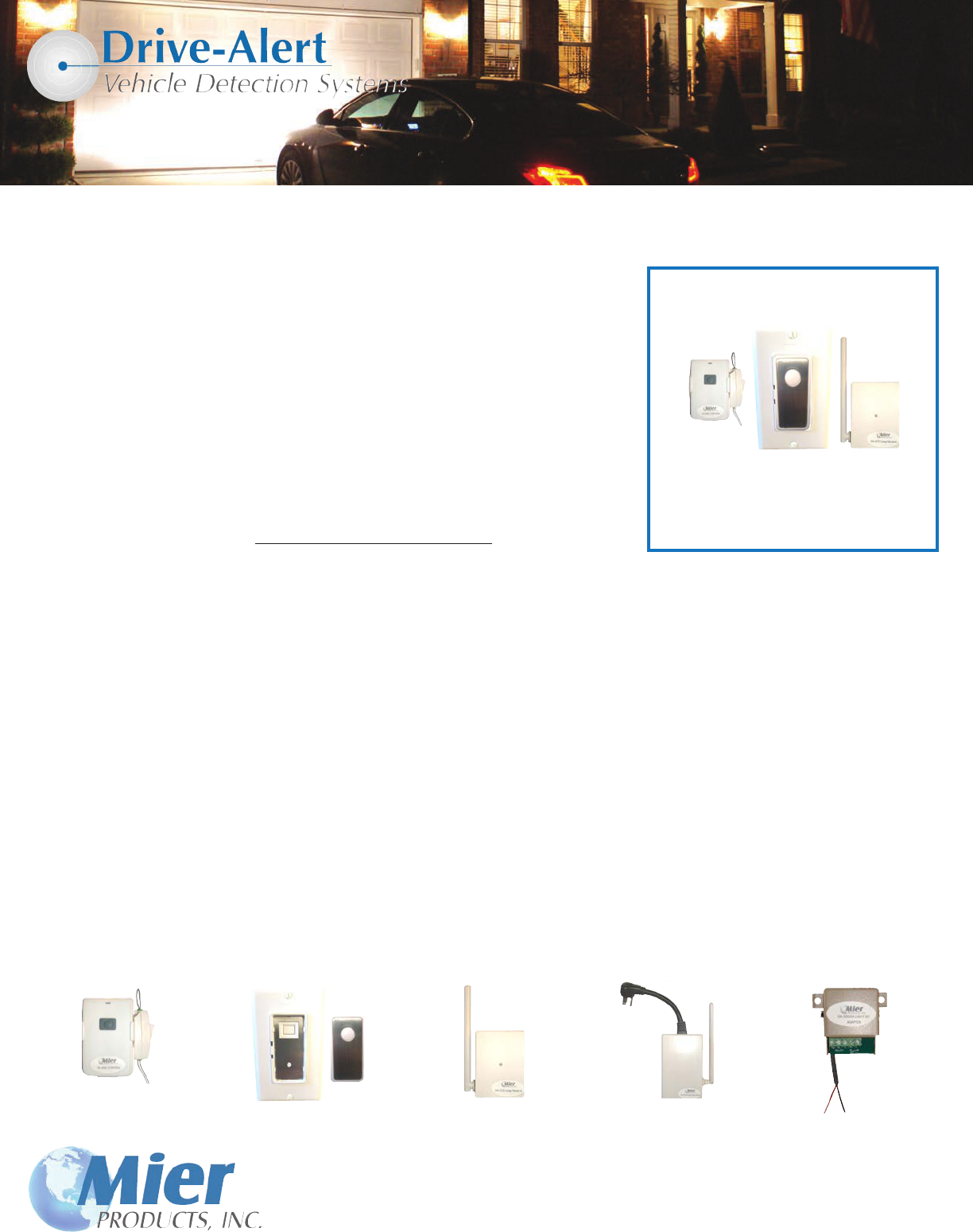
Wireless DA-606LK and DA-606LK2 Light Kits
The DA-606LK Light Kit includes a DA-606 Remote Control Transmitter, DA-071
Wall Light Switch Receiver, and a DA-072 Lamp Module Receiver (pictured at right).
The DA-606LK2 Light Kit includes a DA-606 Remote Control Transmitter,
DA-071 Wall Light Switch Receiver, but DOES NOT include a DA-072 Lamp Module.
The DA-071 Wall Switch can replace an existing light switch, and the DA-072 Lamp
Module can be used in any outlet to turn on a lamp plugged into the DA-072.
The DA-073 Heavy Duty Outlet is an optional accessory.
The DA-071, DA-072, and DA-073 are designed for 120 VAC (see load specs on page 4).
These parts easily hook up to a DA-600 Wireless Drive-Alert or a DA-605 Wireless
Drive-Alert. However, if using a DA-500 Buried Sensor Drive-Alert you must also
order the additional DA-500LKA Light Kit Adapter (see below and next page).
All of the components in our Light Kits are FACTORY PROGRAMMED and set to operate as a matched set. If other devices are
purchased later, the DA-606 Remote Control Transmitter will need to be programmed to operate these units. Programming
instructions are provided at the end of this manual. Erasing the factory programming from any unit is also explained.
The DA-606 Remote Control is triggered by a relay closure in a Drive-Alert control panel. This timer control can be set from 1 to 60
minutes. When triggered, the DA-606 transmits a UHF (318 MHZ) coded radio signal to activate the installed DA-071, DA-072, and
or DA-073 devices for the specic time interval that was set. After the preset time interval, the devices will turn off.
The signal path from the DA-606 to any DA-071, DA-072, and DA-073 devices must be unobstructed by metal objects such as large
appliances, or mirrors. Metal objects/mirrors in the signal path may block the activating signals. If the devices are not working when
a Drive-Alert detects a vehicle, in most cases the problem will be solved by moving the DA-606, and/or the devices, so there is a
clear signal path. Use the “TEST” push-button on the DA-606 to verify operation.
For FREE Technical Support contact Mier Products!
DA-606LK
Wireless Light Kit
The DA-606LK includes:
• one DA-606 Remote Control
• one DA-071 Light Switch with Cover
• one DA-072 Lamp Module
800-473-0213 | [email protected] | www.mierproducts.com
Individual Accessories
DA-606
Remote Control
Transmitter
DA-071
Wireless
Light Switch with Cover
DA-072
Wireless
Lamp Module
DA-073
Wireless
Heavy-Duty Outlet
DA-500LKA
Light Kit Adapter
For DA-500 Drive-Alert

The DA-606 Wireless Control Transmitter activates light switches, lamp modules, and heavy-duty
outlets. The DA-606 ts into the magnetic base cradle and attaches to the Drive-Alert.
The cradle switch on the DA-606 (see Figure A) should be ON to enable the Drive-Alert control of the lights.
If you wish to control the lights manually, and bypass Drive-Alert activation of those lights, such as leaving the
lights on during a party so arriving guests’ cars won’t turn the lights on and off, turn this cradle switch OFF and
the Drive-Alert will have no effect on the lights. Other devices controlled by the Drive-Alert operate as usual.
When using DA-700 Drive-Alert (see Figure B) the wires go to the ALL DETECT “C” Common and “NO”
Normally Open contacts.
When using with a DA-500 Drive-Alert (see Figure C) the whistle switch on the control panel must be in the ON position. The gray wires from the
DA-606 go to the FIRST two contacts on the DA-500LKA Light Kit Adapter. The BLACK wire from the DA-500LKA is attached to the 4th (NEG/GND)
contact on the DA-500 control, and the RED wire is attached to the 6th (NO) contact.
When using DA-600/DA-605 Drive-Alert (see Figure D) the wires from the DA-606 go to the LAST two contacts, “NO” Normally Open and “C”
Common.
DA-600 or DA-605
SIG ALA +5VDC GND +24DC NO NC C NO C
UN REG
Figure D
Figure A
`
DA-500 with whistle ON
Figure C
RED BLACK SHLD NEG +24DC NO NC C
UN REG
NO C NO NC C
DA-500LKA
Black Red
800-473-0213 | [email protected] | www.mierproducts.com
Figure B
DA-700 Control Panel
1 2 3 4 5 6 7 8 9 10 11 12 13 14 15 16 17 18 19 20
+24 Gnd Z-1 Z-2 Z-3 Timer Relay All Det Relay Mute P/B Gnd +12 Not +10,0
DC or Relay Relay Relay 4 5
(Remote) or DC used Low
-24 C NO C NO C NO NC C NO NO C NC -12 Batt
Two Gray wires from the DA-606LK wireless transmitter:
one goes to #13 terminal/All Detect “C” Common, and the other
goes to terminal #12/All Detect “NO” Normally Open.
DA-071 Wireless Light Wall-Switch Receiver
CAUTION: Electrical work is required with the installation of the DA-071 Light Wall Switch, and these instructions MUST be
followed carefully. Mier Products recommends you contact a qualied electrician if you are not experienced with electrical work.
Turn off power to the circuit where you plan to install the Wall Switch. WARNING: FAILURE TO TURN OFF POWER AT THE CIRCUIT BREAKER
CAN RESULT IN ELECTRICAL SHOCK CAUSING SEVER OR FATAL INJURY.
First, remove cover (Figure E above). The DA-071 Wall Switch is designed to operate a maximum load of 1000 watts at 120 VAC.
Follow Figure F above to install the DA-071. Use the provided wire nuts to secure the connections. Black wire to live black wire, red to the lamp
load, and green wire to ground. After the wires are connected, inspect to insure the wires are securely connected and none are exposed. Feed the
gray antenna wire down into the wall and secure the DA-071 Wall Switch to the wall box. Turn the circuit breaker back on to apply power. The
two (2) blue LEDs on the DA-071 should be on. The Wall Switch has been factory set to keep the lights on for ve (5) minutes when activated by a
Drive-Alert control panel or by manually pushing the button on the DA-606 Light Transmitter. This time can be adjusted from 1 minute up to 60 if
the home-owner desires (see Figure G on next page).
Figure E
Remove the cover from the
DA-071 Wall-Switch prior to
installation by gently pulling
it off.
Replace the cover over the
DA-071 Wall-Switch after
installation by gently pressing
into place.
Figure F
Switch Button
Green Ground (usually
copper or green)
Red Load
Black Live Blue
LEDs
Gray Antenna
Don’t cut antenna! SET Button
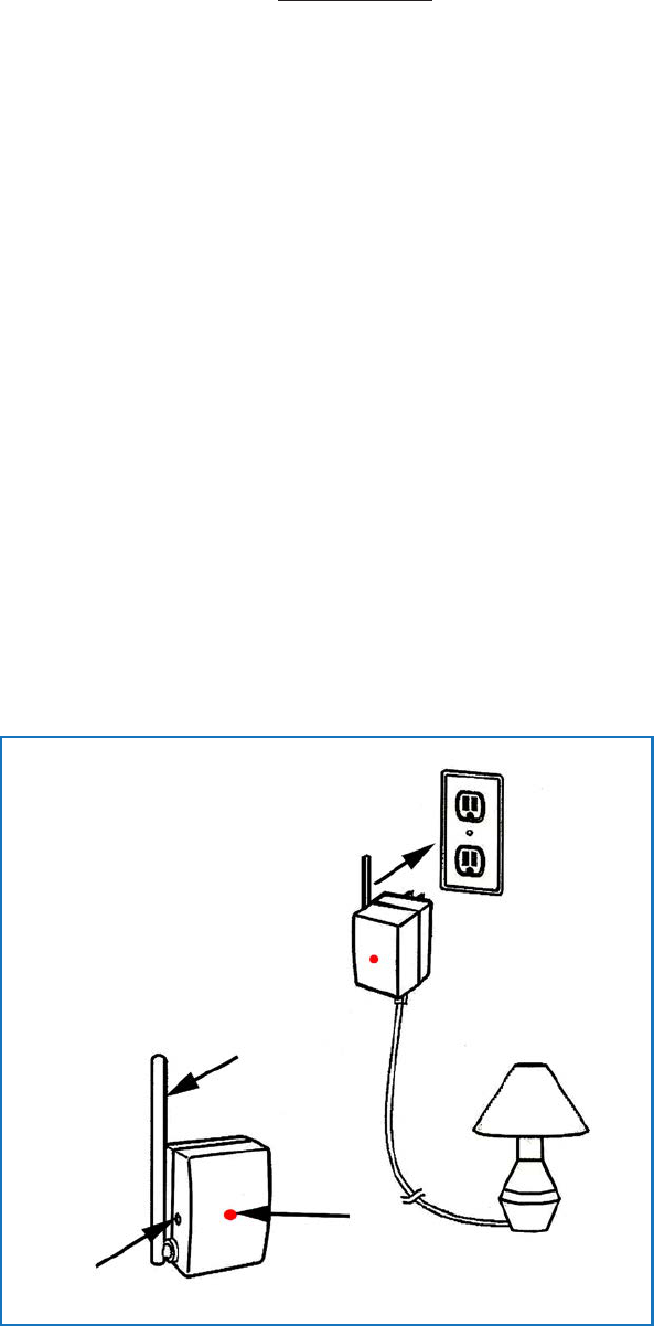
DA-072 Wireless Lamp Module Receiver
The DA-072 Lamp Module is designed to operate a maximum load of 300 watts at 120 VAC. Follow Figure H below to install the DA-072. The
lamp you wish to activate with the DA-072 and Drive-Alert should be on. Plug your lamp into the bottom of the DA-072 Lamp Module and then
plug the DA-072 into a 120 VAC outlet. The Lamp Modules are factory set for a 15 minute time cycle, and will remain on for 15 minutes when
activated by the Drive-Alert or the TEST button on the DA-606 Remote Control. To change this time cycle, rst push the TEST button on the DA-606
to activate the lamp(s). Then, press the SET button on the side of the DA-072 and hold it in until the RED LED ashes for the desired time cycle as
outlined in Figure G above.
The DA-072 does not have an ON/OFF switch and will only respond to commands from the Drive-Alert and/or DA-606 Remote Control.
If you wish to control the lamp(s), and bypass Drive-Alert activation of those lights, such as leaving the lights on during a party so arriving guests’
cars won’t turn the lights on and off, simply unplug the lamp from the DA-072 and then plug the lamp into a 120 VAC outlet.
Figure H
Antenna
Red LED
Plug into AC Socket,
SET load is off
Figure G
To change the time cycle of the DA-071 Wall Switch, the controlled lights must be off and both blue LEDs will be on. Press and hold the SET
button on the Wall Switch. Both blue LEDs will turn off and after about 10 seconds the bottom LED will ash. Release the SET button when the
you see the desired number of ashes and the lights should come on and be in the timing cycle you have set. Use the table below to set the desired
time.
NUMBER OF FLASHES TIME DURATION
1 1 MINUTE
2 5 MINUTES, Factory Setting for DA-071
3 15 MINUTES , Factory Setting for DA-072
4 30 MINUTES
5 60 MINUTES
Once the time duration reaches 5 ashes, it will stay at this setting. To start over, turn the lights off with the Wall Switch and repeat the sequence
above.

Wireless DA-606LK and DA-606LK2 Light Kits
FCC Infortmation:
These devices are approved by the FCC and they comply with part 15 of the FCC rules. Operation is subject to these conditions:
1. These devices may not cause harmful interference.
2. The devices must accept any interference that may cause undesired operation.
3. Modication of the devices may void the right to operate the devices.
SPECIFICATIONS: The DA-606 Remote Control Transmitter operates on 318 mHz
Range between DA-066 Remote Control Transmitter and the DA-071 Wall Switches, DA-072 Lamp
Modules, and/or DA-073 Outlets is about 500 feet in an open area
The DA-606 Remote Control Transmitter uses a CR2032 battery
The DA-071 Wall Switch’s minimum load is 10 watts and maximum load is 1000 watts at 120 VAC
The DA-072 Lamp Module’s minimum load is 10 watts and maximum load is 300 watts at 120 VAC
The DA-073 Heavy-Duty Outlet’s minimum load is 10 watts and maximum load is 1500 watts at 120 VAC
Device Programming (should only be done in rare circumstances when factory settings have been lost):
ERASING FACTORY PROGRAMMING COMMANDS: The Wall Switch must not be in lamp timing mode (lamps off). Turn lamps on by pressing the
Wall Switch button. Two blue LEDs will be off. Press the small red button on the back of the Remote Control Transmitter for 2 seconds. Push the
front button on the Remote Control and the set button on the Wall Switch at the same time for 5 seconds.The upper blue LED will ash when erased,
then both LEDs will ash. Turn lamp off with the Wall Switch and press the front button on the Remote Control to conrm the lamp does not come
on. The Wall Switch will now not respond to Remote Commands.
To erase Lamp Module programming, remove the Lamp Module from the AC outlet. Press and hold the SET button while plugging the Lamp Module
back into the outlet. The RED LED will be on rst, then ash rapidly for about 1 second, then on then off. Now release the SET button. The Lamp
Module will not respond to Remote Control Commands.
PROGRAMMING THE WALL SWITCH:
The Wall Switch must have power applied. Both blue LEDs will be on. Turn switch and lamps on by pushing the wall switch button. Both blue
LEDs will be off. Bring the Remote Control Transmitter near the Wall Switch. Press the SET button on the Wall Switch until the upper blue LED is
on steady. It will ash rst. Release the SET button. You must complete the following steps within 15 seconds. Push the small RED button on the
back of the Remote Control for 1 second, then push the front button for about 3 seconds. The upper blue LED on the Wall Switch will ash and the
bottom blue LED will be blinking. This indicates that the Wall Switch is in 1 minute timing mode and lamps should turn off in 1 minute. The Wall
Switch is now set to operate with the Remote Control. To change the timing of the lamps, see the instructions above. The Remote Control Transmit-
ter may now be reconnected to the Drive-Alert control panel.
PROGRAMMING THE LAMP MODULE:
Plug a lamp into the Lamp Module socket. Plug the Lamp Module into a 120 VAC outlet. The RED light will ash once. The lamp should be off.
Press and hold the SET button on the Lamp Module for about 3 seconds, the RED LED will ash. Release the SET button. Now press and hold the
SET button in for about 10 seconds or until the RED LED is on steady. The next steps must be done in 15 seconds. Press the small RED button on
the back of the Remote Transmitter Control for about 1 second, then press the front
button for about 3 seconds. The RED LED on the Lamp Module will ash then stop ashing. The Lamp Module should now be in the 1 minute
timing mode and should go off in 1 minute. To change the timing, see the instructions above.
800-473-0213 | [email protected] | www.mierproducts.com
Contact us for free installation and technical support:
