
8
ASSEMBLY
NOTE: This Operator’s Manual covers several models. Tractor
features may vary by model. Not all features in this manual are
applicable to all tractor models and the tractor depicted may
differ from yours.
NOTE: All references in this manual to the left or right side and
front or back of the tractor are from the operating position only.
Exceptions, if any, will be specified.
Preparation
MANUALLY MOVING THE TRACTOR
1. Engage the transmission bypass rod to move the tractor
manually without starting it. The transmission bypass rod is
located on the rear of the tractor, on the frame. Engage the
bypass rod by pulling out. See Figure 1.
Figure 1
NOTE: If the tractor will not move or does not move freely when
pushing check if the hydrostatic bypass rod is fully open or the
brake is engaged.
NOTE: The transmission will NOT engage when the hydrostatic
bypass rod is pulled out. Return the rod to its disengaged
position prior to operating the tractor.
2. Disengage the transmission bypass rod by pushing the rod
back in after moving the tractor. See Figure 1.
INSTALL OPERATOR’S SEAT (IF NECESSARY)
To install the seat proceed as follows:
NOTE: The seat is shipped with the seat switch and seat
pan attached.
1. Cut any straps securing the seat assembly to the tractor.
Remove any packing material.
NOTE: Be careful not to cut the wiring harness connecting the
seat and the seat switch.
2. Remove the two shoulder bolts (a) and flange lock nuts (b) in
the seat pan as shown in Figure 2.
(a)
(a)
(b)
(b)
Figure 2
3. Rotate the seat into position and slide a Phillips screwdriver
through one of the seat-securing holes and seat bracket
for alignment.
4. With the previously removed shoulder bolts (a) and flange
lock nuts (b) secure one side of the seat and seat bracket.
While supporting the seat, remove the Phillips screwdriver
and secure the other side of the seat. Be careful not to crimp
or damage the wire harness while installing the seat. See
Figure 3. Torque to 84-103 in-lbs (9.5-11.6 N-m).
(a)
(b)
(a)
(b)
Figure 3
5. Using the harness clip attached to the harness, secure the
excess wire to the fender by snapping the harness clip in place
as shown in Figure 4.
Figure 4

9
ASSEMBLY
INSTALLING THE HOOD COLLAR (IF NECESSARY)
There are three (3) alignment posts (a) on the hood collar (b) that
line up with corresponding alignment holes (c) in the hood (d).
See Figure 5.
(a)
(a)
(a)
(a)
(b)
(c)
(c)
(c)
(d)
Figure 5
Use these alignment points to properly position the hood collar
(a), then secure it in place with the six hex bolts (b) provided in
the hardware bag. Tighten the hex bolts to 102-124 in-lbs (11.5-
14 N-m). See Figure 6.
bb
aa
bb
bb
bb
Figure 6
INSTALLING THE SNAP-ON HOOD TOPPER (IF NECESSARY)
1. To install the snap-on hood topper (a), line up the holes on
the hood topper (a) with the tabs (b) in the hood frame as
shown in Figure 7.
(a)
(b)
(b)
(b)
(b)
Figure 7
2. Insert the tabs into the hood topper and pull back to lock
into place.
3. Once the hood topper is in place, the two locking tabs near
the rear of the hood need to be pushed upward to lock the
hood topper in place. See Figure 8.
Hood Topper Not Shown for Clarity
Figure 8
INSTALLING THE SCREW-ON HOOD TOPPER
(IF NECESSARY)
NOTE: Be careful not to damage the headlight harness when
installing the screw-on hood topper.
1. Set the hood topper up against the top of the hood with the
hood open, and align the holes on the hood.
2. Secure the screw-on hood topper (a) from below, hand-
tighten the screws (b) on the rear half of the hood and then
snug them. See Figure 9.
3. With the rear screws in place, align the holes in the hood
topper (a) with the holes in the hood (c) and secure in place
with remaining two screws (d). See Figure 9.
(a)
(b)
(b)
(d)
(c)
(d)
Figure 9
4. Tighten all four screws to 16-24 in-lbs (1.8-2.7 N-m).
INSTALLING THE PLENUM (IF NECESSARY)
NOTE: Be careful not to damage the headlight harness when
installing the plenum.
To install the plenum (a) onto the hood (b):
1. Insert the rear tabs (c) as shown in Figure 10.
(b)
(a)
(c)
Figure 10

10
ASSEMBLY
2. With the rear tabs installed, insert the front tabs (a) on the
plenum (b) as shown in Figure 11.
(a)
(a)(a)
(b)
(a)(a)
Figure 11
NOTE: The rear tabs fit into a recessed area on the top of
the hood. They slide up from under the hood and into these
recessed areas.
3. Push up on the bottom of the plenum to make sure that the
plenum is securely in place.
4. Secure the headlight harness (a) into the two guides (b) on
the front of the plenum. Figure 12.
(a)
(b)
(b)
Figure 12
INSTALLING THE DASH CAP (IF NECESSARY)
To install the dash cap (a), line up the tabs (b) on the dash cap (a)
with the holes in the upper dash as shown in Figure 13. Slide the
tabs (b) into the holes in the upper dash and push forward on the
dash cap to lock into place.
(a)
(b)
Figure 13
NOTE: Be sure to press on the lower part of the dash cap (a)
facing the operator position to ensure the lower tabs on the dash
cap are in place. See Figure 13.
INSTALLING THE STEERING WHEEL (IF NECESSARY)
The hardware for attaching the steering wheel has been packed
within the steering wheel, beneath the steering wheel cap.
Carefully remove the cover by inserting a small flat screwdriver
into one of the three snap locations, while slowly prying up on
the steering wheel cap to remove the hardware.
IMPORTANT! Do not use impact tools to install or remove
the steering wheel. Doing so can over-torque and damage
the fastener.
1. With the wheels of the tractor pointing straight forward,
align the steering wheel (a) by using the center-line (b) on
the front of the steering wheel (a) pointing straight ahead
and the flat section (c) of the steering wheel (a) facing toward
the seat, place the steering wheel (a) over the steering shaft
(d). See Figure 14.
(e)
(f)
(c)
(a)
(b)
(d)
Figure 14
2. Secure the steering wheel (a) with the hex bolt (e) from
under the steering wheel cap (f) and torque to 18-22 ft-lbs
(24.4-29.8 N-m). See Figure 14.
3. Place the steering wheel cap (f) over the center of the
steering wheel (a) and push downward until it “clicks”
into place.
NOTE: The hex bolt (e) securing the steering wheel (a) has thread
locker applied to it, so if it is removed, it is recommended that the
hex bolt (e) be replaced or thread lock re-applied. See Figure 14.
INSTALLING THE FRONT BUMPER (IF EQUIPPED)
WARNING
Disengage the PTO, engage the brake lock, and stop
the tractor engine before performing any preparation
procedures. Place the tractor on a firm and level surface
before beginning installation or removal procedures.
The exhaust system and surrounding areas are HOT. To avoid
personal injury, allow the tractor to cool before beginning
any installation or removal procedures.

11
ASSEMBLY
The hardware for attaching the front bumper is shipped installed
into the bumper.
1. Remove the four hex screws (a) from the bumper (b). See
Figure 15.
2. Position the bumper brackets to the inside of the tractor’s
frame and secure it in place with the four hex screws (a). See
Figure 15.
(a) (a)
(b)
Figure 15
INSTALLING THE FASTATTACH™ BRUSH GUARD
(IF EQUIPPED)
1. Align the brush guard assembly with the FastAttach™
brackets and push assembly together. See Figure 16.
Figure 16
2. Install the pins on the right and left side of brush guard and
then secure with two cotter pins found in the hardware pack.
See Figure 17.
NOTE: Pulling up lightly on the brush guard may make
installation of the pins easier.
1
2
Figure 17
LOWER DECK DISCHARGE CHUTE DEFLECTOR
WARNING
Never operate the mower deck without the chute deflector
installed and in the down position.
For 46” deck models:
1. Remove the keys attached with a zip tie to the chute bracket.
2. Remove the flange lock nut and hex screw from the deck.
3. Place the chute deflector on the deck, be sure to insert the
tabs on the chute deflector into the holes on the deck. See
Figure 18.
4. Slide the chute deflector toward the rear of the tractor until
the bolt hole in the chute deflector aligns with the hole in the
deck. See Figure 18.
3
4
5
5
4
Figure 18
5. Secure the chute deflector in place with the flange lock nut
and hex screw removed in Step 2. Tighten to 102-124 in-lbs
(11.5-14 N-m). See Figure 18. Skip ahead to Setting the
Deck Wheels.

12
ASSEMBLY
For 42”/50”/54” deck models:
1. Check the tractor deck for a shipping brace that may be
holding the chute deflector upward for shipment. If the
brace is present, it must be removed before operating the
tractor. Holding the chute deflector fully upward, remove the
shipping brace. Lower the chute deflector and discard the
shipping brace. See Figure 19.
Figure 19
SETTING THE DECK WHEELS
NOTE: The deck wheels are an anti-scalp feature of the deck and
are not designed to support the weight of the cutting deck.
1. Move the tractor to a level surface, preferably pavement.
2. Check the tire pressure, adjust, if necessary. See tire sidewall
for proper tire pressure.
3. Make sure the deck is level side-to-side and properly pitched.
See the Service and Maintenance section for deck leveling
information and instructions.
4. Place deck lift lever in the desired mowing height position.
5. Check the wheels for contact or excessive clearance with the
surface below.
NOTE: The deck wheels should have between 1/4”-1/2” (6.35-
12.7 mm) clearance above the ground. Proceed as follows to
adjust the wheels:
a. Raise the deck lift handle to its highest setting.
b. Remove the front (a) and rear (b) deck wheels by
removing the flange lock nuts (c) and shoulder bolts (d)
that secure them to the deck. See Figure 20.
(a)
(b)
(c)
(d)
(d)
(c)
Figure 20
c. Place the deck lift lever in the desired mowing
height setting.
d. Reinsert the shoulder bolt (with each deck wheel) into
the index hole that leaves approximately 1/2” (12.7 mm)
between the bottom of the wheel and the pavement.
Tighten the flange lock nut and shoulder bolt to between
25-30 ft-lbs (33.9-40.7 N-m) using a torque wrench.
Battery Information
WARNING
California Proposition 65 Warning: Battery posts,
terminals, and related accessories contain lead and lead
compounds, chemicals known to the State of California
to cause cancer and reproductive harm. Wash hands
after handling.
WARNING
Should battery acid accidentally splatter into the eyes or
onto the skin, rinse the affected area immediately with
clean cold water. Seek prompt medical attention.
If acid spills on clothing, first dilute it with clean water,
then neutralize with a solution of ammonia/water or
baking soda/water.
NEVER connect (or disconnect) battery charger clips to the
battery while the charger is turned on, as it can cause sparks.
Keep all sources of ignition (cigarettes, matches, lighters)
away from the battery. The gas generated during charging
can be combustible.
As a further precaution, only charge the battery in a well
ventilated area.
Always shield eyes and protect skin and clothing when
working near batteries.
Batteries contain sulfuric acid and may emit explosive
gases. Use extreme caution when handling batteries. Keep
batteries out of the reach of children.
The battery may present a risk of fire or chemical burn if
misused. Do NOT open, disassemble, overheat, or incinerate
the battery.

13
ASSEMBLY
CAUTION
When attaching battery cables, always connect the POSITIVE
(Red) wire to terminal first, followed by the NEGATIVE
(Black) wire.
NOTE: The positive battery terminal is marked Pos. (+). The
negative battery terminal is marked Neg. (–).
CONNECTING THE BATTERY CABLES
WARNING
Always connect the positive lead to the battery before
connecting the negative lead. This will prevent sparking or
possible injury from an electrical short caused by contacting
the tractor body with tools being used to connect cables.
For shipping reasons the factory may leave both battery cables
disconnected from the terminals. To connect the battery cables,
proceed as follows:
NOTE: Wiring harness should lay on top of battery hold down
rod, otherwise damage to the wiring harness may result. See
Figure 22 on page 14.
1. Remove the factory installed hex screws (a) and square
nuts (b) located either on the end of the wiring harness or
in the bag with this manual. Retain the hardware for later
instructions. See Figure 21.
2. Remove the plastic cover (c), if present, from the positive
battery terminal (d) and attach the red cable (e) to the
positive battery terminal (d) with one of the hex screws (a)
and square nuts (b), from Step 1. Use a Philips screw driver.
See Figure 21.
3. Remove the plastic cover (c), if present, from the negative
battery terminal (f) and attach the black cable (g) to the
negative battery terminal (f) with the remaining hex screw
(a) and square nut (b). See Figure 21.
4. Position the red rubber boot over the positive battery
terminal to help protect it from corrosion. See inset in
Figure 21.
NOTE: If the battery is put into service after the date shown
on top/side of battery, charge the battery as instructed in the
Charging the Battery section prior to operating the tractor.
(c)
(c)
(a)
(d)
(e)
(f)
(b)
(a)
(g)
(b)
Figure 21
BATTERY MAINTENANCE
• Some batteries are filled with battery acid and then sealed
at the factory. However, even a “maintenance free” battery
requires some maintenance to ensure its proper life cycle.
• Spray the terminals and exposed wire with a battery
terminal sealer, or coat the terminals with a thin coat of
grease or petroleum jelly, to protect against corrosion.
• Always keep the battery cables and terminals clean and
free of corrosion.
• Some models are equipped with a battery containing a
liquid electrolyte. Handle the battery with care and avoid
tipping to prevent leakage.
BATTERY STORAGE
• When storing the tractor for extended periods, disconnect
the negative battery cable. It is not necessary to remove
the battery.
• All batteries discharge during storage. Keep the exterior
of the battery clean, especially the top. A dirty battery will
discharge more rapidly.
• The battery must be stored with a full charge. A discharged
battery can freeze sooner than a charged battery. A fully
charged battery will store longer in cold temperatures
than hot.
• Recharge the battery before returning to service. Although
the tractor may start, the engine charging system may not
fully recharge the battery.
14
ASSEMBLY
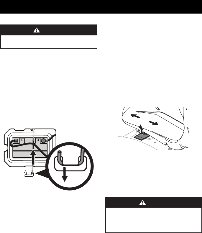
BATTERY REMOVAL
WARNING
Battery posts, terminals, and related accessories contain
lead and lead compounds. Wash hands after handling.
The battery is located beneath the seat frame. To remove
the battery:
1. Remove the hex screw and square nut securing the black
negative battery lead to the negative battery post (marked
NEG (-)). Move the cable away from the negative battery post.
2. Remove the hex screw and square nut securing the red
positive battery lead to the positive battery post (marked
POS (+)).
3. Remove the battery hold down rod by pushing the hooked
end out of the tab on the fender to the right side of the
battery. Then flip the battery hold down rod up to free the
battery. See Figure 22.
Figure 22
4. Carefully lift the battery out of the tractor.
5. Install the battery by repeating the above steps in the
reverse order.
CHARGING THE BATTERY
Test and, if necessary, recharge the battery after the tractor has
been stored for a period of time.
Models with Lead-Acid Battery
• A voltmeter or load tester reading of 12.4 volts (DC) or lower
across the battery terminals indicates that the battery
needs to be charged.
• A lead-acid battery charger should be used. Recommended
charge rate is 4A/14.7V.
• If your battery charger is automatic, charge the battery
until the charger indicates that charging is complete. If the
charger is not automatic, charge for no fewer than eight
(8) hours.
Models with AGM Battery
• An AGM battery charger should be used. Recommended
charge rate is 1.1A/14.8V.
IMPORTANT! Do NOT use an automotive charger.
• If your battery charger is automatic, charge the battery
until the charger indicates that charging is complete. If the
charger is not automatic, charge for no fewer than eight
(8) hours.
Adjusting the Seat
To adjust the position of the seat, lift the seat adjustment lever
up. Slide the seat forward or rearward to the desired position;
then release the adjustment lever. Make sure seat is locked into
position before operating the tractor. See Figure 23.
Figure 23
Oil
NOTE: Your tractor is shipped with oil in the engine. However,
you MUST check the oil level before operating. See the Engine
Operator’s Manual for instructions on checking, adding and
changing oil.
CAUTION
Always check the engine oil level before each use as
instructed in the Engine Operator’s Manual. Add oil as
necessary. Failure to do so may result in serious damage to
your engine.
