
Standards Research and Development Branch
Motor Vehicle Safety Directorate
TRANSPORT CANADA
Ottawa, Ontario
K1A 0N5
TECHNICAL STANDARDS DOCUMENT
No. 108, Revision 7
Lamps, Reective Devices, and
Associated Equipment
The text of this document is based on Federal Motor Vehicle Safety Standard No.
108,
Lamps, Reective Devices, and Associated Equipment, as published in the U.S. Code of
Federal Regulations, Title
49, Chapter V, Part
571, as it read on February 8, 2016.
Publication Date:
Effective Date:
Mandatory Compliance Date:
February
04, 2021
February
04, 2021
February 04, 2021

i
Effective:
February 04, 2021
Technical Standards Document
Number 108, Revision 7
Lamps, Reective Devices, and
Associated Equipment
(Ce document est aussi disponible en français.)
Introduction
As dened by section 12 of the
Motor Vehicle Safety Act, a Technical Standards Document
(TSD) is a document that reproduces an enactment of a foreign government (e.g. a Federal
Motor Vehicle Safety Standard issued by the U.S. National Highway Trafc Safety
Administration). According to the Act, the
Motor Vehicle Safety Regulations
may alter or
override some provisions contained in a TSD or specify additional requirements; consequently,
it is advisable to read a TSD in conjunction with the Act and its counterpart Regulation. As a
guide, where the corresponding Regulation contains additional requirements, footnotes indicate
the amending subsection number.
TSDs are revised from time to time in order to incorporate amendments made to the reference
document, at which time a Notice of Revision is published in the
Canada Gazette
Part
I. All
TSDs are assigned a revision number, with “Revision
0” designating the original version.
Identication of Changes
In order to facilitate the incorporation of a TSD, certain non-technical changes may be made to
the foreign enactment. These may include the deletion of words, phrases, gures, or sections
that do not apply under the Act or Regulations, the conversion of imperial to metric units,
the deletion of superseded dates, and minor changes of an editorial nature. Additions are
underlined, and provisions that do not apply are
stroked through. Where an entire section has
been deleted, it is replaced by: “[CONTENT NOT REPRODUCED]”. Changes are also made
where there is a reporting requirement or reference in the foreign enactment that does not apply
in Canada. For example, the name and address of the U.S. Department of Transportation are
replaced by those of the Department of Transport.
Effective Dates
The effective date of a TSD is the date of publication of its incorporating regulation or of
the notice of revision in the Canada Gazette, and the date as of which voluntary compliance
is permitted. The mandatory compliance date is the date upon which compliance with the
requirements of the TSD is obligatory. If the effective date and mandatory compliance date are
different, manufacturers may follow the requirements that were in force before the effective
date, or those of this TSD, until the mandatory compliance date.

Lamps, Reective Devices, and Associated Equipment
ii
In the case of an initial TSD, or when a TSD is revised and incorporated by reference by
an amendment to the Regulations, the mandatory compliance date is as specied in the
Regulations, and it may be the same as the effective date. When a TSD is revised with no
corresponding changes to the incorporating Regulations, the mandatory compliance date is six
months after the effective date.
Ofcial Version of Technical Standards Documents
Technical Standards Documents may be consulted electronically in both HTML and Portable
Document Format (PDF) on the Department of Transport’s Web site at http://www.tc.gc.ca/
eng/acts-regulations/regulations-crc-c1038.htm. The PDF version is a replica of the TSD as
published by the Department and is to be used for the purposes of legal interpretation and
application. The HTML version is provided for information purposes only.
(Original signed by)
Director, Standards Research and Development
for the Minister of Transport,
Ottawa, Ontario
Effective:
February 04, 2021
TSD No. 108, Revision 7

Lamps, Reective Devices, and Associated Equipment
iii
Table of Contents
Introduction .......................................................................................................................... i
Identication of Changes
..................................................................................................... i
Effective Dates ...................................................................................................................... i
Ofcial Version of Technical Standards Documents ........................................................ ii
S1 Scope. ........................................................................................................................... 1
S2 Purpose. ....................................................................................................................... 1
S3 Application.................................................................................................................... 1
S4 Denitions. ................................................................................................................... 1
S5 References to SAE publications. ................................................................................ 7
S6 Vehicle requirements. ................................................................................................ 8
S6.1 Required lamps, reective devices, and associated equipment by vehicle type. .. 8
S6.2 Impairment. ......................................................................................................... 10
S6.3 Equipment combinations. ....................................................................................11
S6.4 Lens area, visibility and school bus signal lamp aiming. ....................................11
S6.5 Marking. .............................................................................................................. 12
S6.6 Associated equipment. ......................................................................................... 14
S6.7 Replacement equipment. ...................................................................................... 14
S7 Signal lamp requirements. ....................................................................................... 14
S7.1 Turn signal lamps. ................................................................................................ 14
S7.2 Taillamps . ............................................................................................................ 19
S7.3 Stop lamps. .......................................................................................................... 20
S7.4 Side marker lamps. ............................................................................................. 22
S7.5 Clearance and identication lamps. .................................................................... 23
S7.6 Backup lamps. ..................................................................................................... 24
S7.7 License plate lamps. ............................................................................................ 24
S7.8 Parking lamps. .................................................................................................... 26
S7.9 High-mounted stop lamps. .................................................................................. 26
Effective:
February 04, 2021
TSD No. 108, Revision 7

Lamps, Reective Devices, and Associated Equipment
iv
S7.10 Daytime running lamps (DRLs). ....................................................................... 27
S7.11 School bus signal lamps. ................................................................................... 28
S8 Reective device requirements. .............................................................................. 29
S8.1 Reex reectors. ................................................................................................. 29
S8.2 Conspicuity systems. ........................................................................................... 30
S9 Associated equipment requirements. ..................................................................... 34
S9.1 Turn signal operating unit. .................................................................................. 34
S9.2 Turn signal asher. .............................................................................................. 34
S9.3 Turn signal pilot indicator tell-tale. .................................................................... 34
S9.4 Headlamp beam switching device. ...................................................................... 35
S9.5 Upper beam headlamp indicator tell-tale. ........................................................... 35
S9.6 Vehicular hazard warning signal operating unit. ................................................ 36
S9.7 Vehicular hazard warning signal asher. ............................................................ 36
S9.8 Vehicular hazard warning signal pilot indicator tell-tale. ................................... 36
S10 Headlighting system requirements. ...................................................................... 37
S10.1 Vehicle headlighting systems. ........................................................................... 37
S10.2 [Reserved] ....................................................................................................... 37
S10.3 Number. See Tables I-a and I-c. ........................................................................ 37
S10.4 Color of light. See Tables I-a and I-c. ................................................................ 37
S10.5 Mounting location. See Tables I-a and I-c and S6.1.3.5. ................................... 37
S10.6 Mounting height. See Tables I-a and I-c. ........................................................... 37
S10.7 Activation. See Tables I-a and I-c, Table II, and S6.1.5. ................................... 37
S10.8 Effective projected luminous lens area. No requirement. .................................. 37
S10.9 Visibility. No requirement. ................................................................................. 37
S10.10 Indicator Tell-tale. See S9.5. ............................................................................ 37
S10.11 Markings. See S6.5. ......................................................................................... 37
S10.12 Spacing to other lamps. See S6.1.3.5. .............................................................. 37
S10.13 Sealed beam headlighting systems. ................................................................ 37
Effective:
February 04, 2021
TSD No. 108, Revision 7

Lamps, Reective Devices, and Associated Equipment
v
S10.14 Integral beam headlighting systems. ............................................................... 38
S10.15 Replaceable bulb headlighting systems. ......................................................... 40
S10.16 Combination headlighting systems. ................................................................ 41
S10.17 Motorcycle headlighting systems. .................................................................. 42
S10.18 Headlamp aimability performance requirements (except for motorcycles) .... 44
S11 Replaceable light source requirements. ............................................................... 50
S11.1 Markings. .......................................................................................................... 50
S11.2 Ballast markings. .............................................................................................. 50
S11.3 Gas discharge laboratory life. ........................................................................... 51
S11.4 Physical tests. .................................................................................................... 51
S12 Headlamp concealment device requirements. ..................................................... 51
S13 Replaceable headlamp lens requirements. .......................................................... 52
S14 Physical and photometry test procedures and performance requirements. ..... 52
S14.1 General test procedures and performance requirements. .................................. 52
S14.2 Photometric test procedures. ............................................................................. 53
S14.3 Motorcycle headlamp out of focus test procedure and performance
requirements. .....................................................................................................59
S14.4 General test procedures and performance requirements. .................................. 60
S14.5 Signal lamp and reective device physical test procedures and performance
requirements. .....................................................................................................64
S14.6 Headlamp physical test procedures and performance requirements. ................ 65
S14.7 Replaceable light source physical test procedures and performance
requirements. ......................................................................................................76
S14.8 Vehicle headlamp aiming devices (VHAD) physical test procedures and
performance requirements. ................................................................................78
S14.9 Associated equipment physical test procedures and performance
requirements. ......................................................................................................79
Effective:
February 04, 2021
TSD No. 108, Revision 7

Lamps, Reective Devices, and Associated Equipment
vi
LIST OF TABLES
Table I-a—Required Lamps and Reective Devices...................................................... 92
Table I-b—Required Lamps and Reective Devices
..................................................... 99
Table I-c—Required Lamps and Reective Devices .................................................... 103
Table II-a—Headlighting Systems - Sealed Beams ...................................................... 106
Table II-b—Headlighting Systems - Combination ...................................................... 107
Table II-c—Headlighting Systems - Integral Beams ................................................... 108
Table II-d—Headlighting Systems - Replaceable Bulb ............................................... 109
Table III—Marking Requirements Location
................................................................110
Table IV-a—Effective Projected Luminous Lens Area Requirements ........................112
Table IV-b—Effective Projected Luminous Lens Area Requirements .......................113
Table IV-c—Effective Projected Luminous Lens Area Requirements
........................113
Table V-a—Visibility Requirements of Installed Lighting Devices .............................113
Table V-b—Visibility Requirements of Installed Lighting Devices - Lens Area
Visibility Option
...............................................................................................................114
Table V-c—Visibility Requirements of Installed Lighting Devices - Luminous
Intensity Visibility Option ...............................................................................................115
Table V-d—Visibility Requirements of Installed Lighting Devices
(Legacy Visibility Alternative)
........................................................................................116
Table VI-a—Front Turn Signal Lamp Photometry Requirements .............................117
Table VI-b—Front Turn Signal Lamp Photometry Requirements
.............................118
Table VII—Rear Turn Signal Lamp Photometry Requirements ................................119
Table VIII—Taillamp Photometry Requirements ....................................................... 120
Table IX—Stop Lamp Photometry Requirements....................................................... 121
Table X—Side Marker Lamp Photometry Requirements
.......................................... 122
Table XI—Clearance and Identication Lamps Photometry Requirements ............ 123
Table XII—Backup Lamp Photometry Requirements
................................................ 124
Table XIII-a—Motorcycle Turn Signal Lamp Alternative Photometry
Requirements
................................................................................................................... 125
Effective:
February 04, 2021
TSD No. 108, Revision 7

Lamps, Reective Devices, and Associated Equipment
vii
Table XIII-b—Motor Driven Cycle Limited Speed Motorcycle Stop Lamp
Alternative Photometry Requirements ......................................................................... 126
Table XIV—Parking Lamp Photometry Requirements .............................................. 127
Table XV—High Mounted Stop Lamp Photometry Requirements
........................... 128
Table XVI-a—Reex Reector Photometry Requirements ........................................ 129
Table XVI-b—Additional Photometry Requirements for Conspicuity
Reex Reectors
............................................................................................................. 129
Table XVI-c—Retroreective Sheeting Photometry Requirements ........................... 130
Table XVII—School Bus Signal Lamp Photometry Requirements ........................... 131
Table XVIII—Headlamp Upper Beam Photometry Requirements
........................... 132
Table XIX-a—Headlamp Lower Beam Photometry Requirements ........................... 133
Table XIX-b—Headlamp Lower Beam Photometry Requirements........................... 134
Table XIX-c—Headlamp Lower Beam Photometry Requirements
........................... 135
Table XX—Motorcycle and Motor Driven Cycle Limited Speed Motorcycle
Photometry Requirements ............................................................................................. 136
LIST OF FIGURES
Figure 1—Chromaticity Diagram ................................................................................. 137
Figure 2—Flasher Performance Chart ......................................................................... 138
Figure 3—Replaceable Bulb Headlamp Aim Pads ...................................................... 139
Figure 4—Headlamp Connector Test Setup
................................................................. 140
Figure 5—Headlamp Abrasion Test Fixture ................................................................ 141
Figure 6—Thermal Cycle Prole ................................................................................... 142
Figure 7—Dirt / Ambient Test Setup
............................................................................. 143
Figure 8—Replaceable Light Source Deection Test Setup ........................................ 144
Figure 9—Environmental Test Prole .......................................................................... 145
Figure 10—Replaceable Light Source Pressure Test Setup
........................................ 146
Figure 11—Trailer Conspicuity Treatment Examples ................................................. 147
Figure 12-1—Trailer Conspicuity Detail I
.................................................................... 148
Figure 12-2—Trailer Conspicuity Detail II
.................................................................. 149
Effective:
February 04, 2021
TSD No. 108, Revision 7

Lamps, Reective Devices, and Associated Equipment
viii
Figure 13—Tractor Conspicuity Treatment Examples ............................................... 150
Figure 14 — Type F: Headlamp Aim Deection Test Setup........................................ 151
Figure 15 — Types G and H: Headlamp Aim Deection Test Setup .......................... 151
Figure 16 — Types A and E: Headlamp Aim Deection Test Setup
........................... 151
Figure 17 — Type B: Headlamp Aim Deection Test Setup ....................................... 151
Figure 18 — Types C and D: Headlamp Aim Deection Test Setup .......................... 151
Figure 19—License Plate Lamp Target Locations
....................................................... 152
Figure 20—License Plate Lamp Measurement of Incident Light Angle ................... 153
Figure 21—Vibration Test Machine .............................................................................. 154
Figure 22—Flasher Standard Test Circuit
................................................................... 155
Effective:
February 04, 2021
TSD No. 108, Revision 7

Lamps, Reective Devices, and Associated Equipment
1
1 For applicability, see Schedule III and section 108 of Schedule IV of the Motor Vehicle Safety Regulations
(MVSR).
Effective:
February 04, 2021
TSD No. 108, Revision 7
Technical Standards Document
Number 108, Revision 7
Lamps, Reflective Devices, and
Associated Equipment
S1
Scope.
This
Technical Standards Document (TSD)
standard
species requirements for original
and
replacement
lamps, reective devices, and associated equipment.
S2
Purpose.
The purpose of this
TSD
standard
is to reduce trafc accidents and deaths and injuries resulting
from trafc accidents, by providing adequate illumination of the roadway, and by enhancing the
conspicuity of motor vehicles on the public roads so that their
presence is perceived and their
signals understood, both in daylight and in darkness or other conditions of reduced visibility.
S3
Application.
1
[CONTENT NOT REPRODUCED]
S4
Denitions.
Aiming plane
means a plane dened by the surface of the three aiming pads on the lens.
(plan
d’orientation)
Aiming reference plane
means a plane which is perpendicular to the longitudinal axis
of the
vehicle and tangent to the forwardmost aiming pad on the headlamp.
(plan d’orientation repère)
Aiming screws
are the horizontal and vertical adjusting screws with self-locking features used to
aim and retain a headlamp unit in the proper position.
(vis d’orientation)

Lamps, Reective Devices, and Associated Equipment
2
Axis of reference means the characteristic axis of the lamp for use as the direction of reference
(H = 0°, V = 0°) for angles of eld for photometric measurements and for installing the lamp on
the vehicle.
(axe de référence)
Backup lamp means a lamp or lamps which illuminate the road to the rear of a vehicle and
provide a warning signal to pedestrians and other drivers when the vehicle is backing up or is
about to back up. (feu de recul)
Beam contributor means an indivisible optical assembly including a lens, reector, and light
source, that is part of an integral beam headlighting system and contributes only a portion of a
headlamp beam. (projecteur contribuant)
Cargo lamp is a lamp that is mounted on a multipurpose passenger vehicle, truck, or bus
for the purpose of providing illumination to load or unload cargo. (dispositif d’éclairage du
compartiment de charge)
Clearance lamps are lamps which show to the front or rear of the vehicle, mounted on the
permanent structure of the vehicle as near as practicable to the upper left and right extreme
edges to indicate the overall width and height of the vehicle. (feux de gabarit)
Coated materials means a material which has a coating applied to the surface of the nished
sample to impart some protective properties. Coating identication means a mark of the
manufacturer’s name, formulation designation number, and recommendations for application.
(matériaux enrobés)
Color Fundamental denitions of color are expressed by Chromaticity Coordinates according
to the CIE 1931 Standard Colorimetric System, as described in the CIE 1931 Chromaticity
Diagram (
incorporated by reference, see § 571.5). (couleur)
Color bleeding means the migration of color out of a plastic part onto the surrounding surface.
(saignement)
Combination clearance and side marker lamps are single lamps which simultaneously fulll the
requirements of clearance and side marker lamps. (combinaison feu de gabarit et feu de position)
Combination headlamp means a headlamp that is a combination of two different headlamp
types chosen from a type F sealed beam headlamp, an integral beam headlamp, or a replaceable
bulb headlamp. (combinaison de projecteurs)
Cracking means a separation of adjacent sections of a plastic material with penetration into the
specimen. (craquelage)
Crazing means a network of apparent ne cracks on or beneath the surface of materials.
(ssuration)
Cutoff means a generally horizontal, visual/optical aiming cue in the lower beam that marks a
separation between areas of higher and lower luminance. (coupure)
Effective:
February 04, 2021
TSD No. 108, Revision 7

Lamps, Reective Devices, and Associated Equipment
3
2
Daytime running lamps (DRLs) are steady burning lamps that are used to improve the
conspicuity of a vehicle from the front and front sides when the regular headlamps are not
required for driving. (Feux de jour (FDJ))
Delamination means a separation of the layers of a material including coatings. (délamination)
Design voltage means the voltage used for design purposes. (tension de calcul)
Direct reading indicator means a device that is mounted in its entirety on a headlamp or
headlamp aiming or headlamp mounting equipment, is part of a VHAD, and provides
information about headlamp aim in an analog or digital format. (indicateur à lecture directe)
Effective light-emitting surface means that portion of a lamp that directs light to the
photometric test pattern, and does not include transparent lenses, mounting hole bosses,
reex reector area, beads or rims that may glow or produce small areas of increased
intensity as a result of uncontrolled light from an area of
1
⁄
2
° radius around a test point.
(surface de sortie efcace de la lumière)
Effective projected luminous lens area means the area of the orthogonal projection of the
effective light-emitting surface of a lamp on a plane perpendicular to a dened direction relative
to the axis of reference. Unless otherwise specied, the direction is coincident with the axis of
reference. (surface lumineuse efcace projetée d’une lentille)
Exposed means material used in lenses or optical devices exposed to direct sunlight as installed
on the vehicle. (exposé)
Filament means that part of the light source or light emitting element(s), such as a resistive
element, the excited portion of a specic mixture of gases under pressure, or any part of other
energy conversion sources, that generates radiant energy which can be seen. (lament)
2
Flash means a cycle of activation and deactivation of a lamp by automatic means continuing
until stopped either automatically or manually. (clignotement)
Fully opened means the position of the headlamp concealment device in which the headlamp is
in the design open operating position. (entièrement ouvert)
H-V axis means the line from the center of the principal lament of a lamp to the intersection of
the horizontal (H) and vertical (V) lines of a photometric test screen. (axe H-V)
Haze means the cloudy or turbid appearance of an otherwise transparent specimen caused by
light scattered from within the specimen or from its surface. (obscurcissement)
2
Headlamp means a lighting device providing an upper and/or a lower beam used for providing
illumination forward of the vehicle. (projecteur)
Headlamp concealment device means a device, with its operating system and components, that
provides concealment of the headlamp when it is not in use, including a movable headlamp
2 See the Motor Vehicle Safety Regulations (MVSR), subsection 2(1), for the applicable denition
Effective:
February 04, 2021
TSD No. 108, Revision 7

Lamps, Reective Devices, and Associated Equipment
4
cover and a headlamp that displaces for concealment purposes. (dispositif de dissimulation de
projecteur)
Headlamp mechanical axis means the line formed by the intersection of a horizontal and a
vertical plane through the light source parallel to the longitudinal axis of the vehicle. If the
mechanical axis of the headlamp is not at the geometric center of the lens, then the location will
be indicated by the manufacturer on the headlamp. (axe mécanique du projecteur)
Headlamp test xture means a device designed to support a headlamp or headlamp assembly in
the test position specied in the laboratory tests and whose mounting hardware and components
are those necessary to operate the headlamp as installed in a motor vehicle. (appareil d’essai de
projecteur)
High-mounted stop lamp means a lamp mounted high and possibly forward of the tail, stop, and
rear turn signal lamps intended to give a steady stop warning through intervening vehicles to
operators of following vehicles. (feu de freinage surélevé)
Identification lamps are lamps used in groups of three, in a horizontal row, which show to the
front or rear or both, having lamp centers spaced not less than [6 in] 152 mm nor more than
[12 in] 304 mm apart, mounted on the permanent structure as near as practicable to the vertical
centerline and the top of the vehicle to identify certain types of vehicles. (feux d’identication)
Integral beam headlamp means a headlamp (other than a standardized sealed beam headlamp
designed to conform to paragraph S10.13 or a replaceable bulb headlamp designed to conform
to paragraph S10.15) comprising an integral and indivisible optical assembly including lens,
reector, and light source, except that a headlamp conforming to paragraph S10.18.8 or
paragraph S10.18.9 may have a lens designed to be replaceable. (projecteur à faisceau intégré)
License plate lamp means a lamp used to illuminate the license plate on the rear of a vehicle.
(lampe de plaque d’immatriculation)
2
Lower beam means a beam intended to illuminate the road and its environs ahead of the
vehicle when meeting or closely following another vehicle. (faisceau-de croisement)
Material means the type and grade of plastics, composition, and manufacturer’s designation
number and color. (matériau)
Mechanically aimable headlamp means a headlamp having three pads on the lens, forming an
aiming plane used for laboratory photometric testing and for adjusting and inspecting the aim of
the headlamp when installed on the vehicle. (projecteur orientable de façon mécanique)
3
Motor driven cycle means every motorcycle, including every motor scooter, with a motor
which produces not more than 5 horsepower, and every bicycle with motor attached.
(cyclomoteur)
3 See the Motor Vehicle Safety Regulations (MVSR), subsection 2(1), for the applicable definition of limited-
speed motorcycle.
Effective:
February 04, 2021
TSD No. 108, Revision 7

Lamps, Reective Devices, and Associated Equipment
5
Motorcycle or motor driven cycle limited speed motorcycle headlamp means a major lighting
device used to produce general illumination ahead of the vehicle. (projecteur de motocyclette
ou de cyclomoteur motocyclette à vitesse limitée)
Mounting ring means the adjustable ring upon which a sealed beam unit is mounted. (anneau
de montage)
Mounting ring (type F sealed beam) means the adjustable ring upon which a sealed beam unit is
mounted and which forces the sealed beam unit to seat against the aiming ring when assembled
into a sealed beam assembly. (anneau de retenue (projecteur scellé de type F))
Multiple compartment lamp means a device which gives its indication by two or more
separately lighted areas which are joined by one or more common parts, such as a housing or
lens. (feu à compartiments multiples)
Multiple lamp arrangement means an array of two or more separate lamps on each side of the
vehicle which operate together to give a signal. (arrangement à feux multiples)
Optically combined means a lamp having a single or two lament light source or two or more
separate light sources that operate in different ways, and has its optically functional lens area
wholly or partially common to two or more lamp functions. (combiné optiquement)
Overall width means the nominal design dimension of the widest part of the vehicle, exclusive
of signal lamps, marker lamps, outside rearview mirrors, exible fender extensions, mud aps,
and outside door handles determined with doors and windows closed, and the wheels in the
straight-ahead position. Running boards may also be excluded from the determination of overall
width if they do not extend beyond the width as determined by the other items excluded by this
denition. (largeur hors tout)
Parking lamps are lamps on both the left and right of the vehicle which show to the front and
are intended to mark the vehicle when parked or serve as a reserve front position indicating
system in the event of headlamp failure. (feux de stationnement)
Protected means material used in inner lenses for optical devices where such lenses are
protected from exposure to the sun by an outer lens made of materials meeting the requirements
for exposed plastics. (Protégé)
Rated voltage means the nominal circuit or vehicle electrical system voltage classication.
(tension nominale)
2
Reex reectors are devices used on vehicles to give an indication to approaching drivers
using reected light from the lamps of the approaching vehicle. (cataphotes)
Remote reading indicator means a device that is not mounted in its entirety on a headlamp or
headlamp aiming or headlamp mounting equipment, but otherwise meets the denition of a
direct reading indicator. (téléindicateur)
Effective:
February 04, 2021
TSD No. 108, Revision 7

Lamps, Reective Devices, and Associated Equipment
6
Replaceable bulb headlamp means a headlamp comprising a bonded lens and reector
assembly and one or two replaceable light sources, except that a headlamp conforming to
paragraph S10.18.8 or paragraph S10.18.9 may have a lens designed to be replaceable.
(projecteur à ampoule remplaçable)
Replaceable light source means an assembly of a capsule, base, and terminals that is designed
to conform to the requirements of appendix A or appendix B
of
49 part 564 Replaceable Light
Source Information of this Chapter V of title 49 of the U.S. Code of Federal Regulations (CFR)
(hereinafter referred to as part 564). (source lumineuse remplaçable)
Retaining ring means the clamping ring that holds a sealed beam unit against a mounting ring.
(anneau de retenue)
Retaining ring (type F sealed beam) means the clamping ring that holds a sealed beam unit
against a mounting ring, and that provides an interface between the unit’s aiming/seating pads
and the headlamp aimer adapter (locating plate). (anneau de retenue (projecteur scellé de
type F))
School bus signal lamps are alternately ashing lamps mounted horizontally both front and rear,
intended to identify a vehicle as a school bus and to inform other users of the highway that such
vehicle is stopped on the highway to take on or discharge school children. (feux de signalisation
d’autobus scolaire)
Sealed beam headlamp means an integral and indivisible optical assembly including the light
source with “SEALED BEAM” molded in the lens. (projecteur scellé)
Sealed beam headlamp assembly means a major lighting assembly which includes one or
more sealed beam units used to provide general illumination ahead of the vehicle. (montage de
projecteur scellé)
Seasoning means the process of energizing the lament of a headlamp at design voltage for a
period of time equal to 1% of design life, or other equivalent method. (vieillissement)
Semiautomatic headlamp beam switching device is one which provides either automatic or
manual control of beam switching at the option of the driver. When the control is automatic the
headlamps switch from the upper beam to the lower beam when illuminated by the headlamps
on an approaching vehicle and switch back to the upper beam when the road ahead is dark.
When the control is manual, the driver may obtain either beam manually regardless of the
conditions ahead of the vehicle. (dispositif de commutation de faisceau de projecteur semi-
automatique)
Side marker lamps are lamps which show to the side of the vehicle, mounted on the permanent
structure of the vehicle as near as practicable to the front and rear edges to indicate the overall
length of the vehicle. Additional lamps may also be mounted at intermediate locations on the
sides of the vehicle. (feux de position latéraux)
Effective:
February 04, 2021
TSD No. 108, Revision 7

Lamps, Reective Devices, and Associated Equipment
7
Stop lamps are lamps giving a steady light to the rear of a vehicle to indicate a vehicle is
stopping or diminishing speed by braking. (feux de freinage)
Taillamps are steady burning low intensity lamps used to designate the rear of a vehicle. (feux
arrière)
Test voltage means the specied voltage and tolerance to be used when conducting a test.
(tension d’essai)
Turn signal lamps are the signaling element of a turn signal system which indicates the
intention to turn or change direction by giving a ashing light on the side toward which the turn
will be made. (feux de changement de direction)
Turn signal asher means a device which causes a turn signal lamp to ash as long as it is
turned on. (clignotant des feux de changement de direction)
Turn signal operating unit means an operating unit that is part of a turn signal system by which
the operator of a vehicle causes the signal units to function. (dispositif activant les feux de
changement de direction)
2
Upper beam means a beam intended primarily for distance illumination and for use when not
meeting or closely following other vehicles. (faisceau-de route)
Vehicle headlamp aiming device or VHAD means motor vehicle equipment, installed either on
a vehicle or headlamp, which is used for determining the horizontal or vertical aim, or both the
vertical and horizontal aim of the headlamp. (dispositif d’orientation intégré du véhicule ou
DOIV)
Vehicular hazard warning signal asher means a device which, as long as it is turned on, causes
all the required turn signal lamps to ash. (clignotant des signaux de détresse du véhicule)
Vehicular hazard warning signal operating unit means a driver controlled device which causes
all required turn signal lamps to ash simultaneously to indicate to approaching drivers the
presence of a vehicular hazard. (dispositif activant les signaux de détresse du véhicule)
Visually/optically aimable headlamp means a headlamp which is designed to be visually/
optically aimable in accordance with the requirements of paragraph S10.18.9 of this TSD
standard. (projecteur orientable visuellement/optiquement)
S5 References to SAE publications.
Each required lamp, reective device, and item of associated equipment must be designed to
conform to the requirements of applicable SAE publications as referenced and subreferenced
in this TSD standard. The words “it is recommended that,” “recommendations,” or “should be”
appearing in any SAE publication referenced or subreferenced in this TSD standard must be
read as setting forth mandatory requirements.
Effective:
February 04, 2021
TSD No. 108, Revision 7

Lamps, Reective Devices, and Associated Equipment
8
S6 Vehicle requirements.
S6.1 Required lamps, reective devices, and associated
equipment by vehicle type.
S6.1.1 Quantity. Except as provided in succeeding paragraphs of this S6.1.1 each vehicle
must be equipped with at least the number of lamps, reective devices, and items of associated
equipment specied for that vehicle type and size in Table I and Section 6.6, designed to
conform to the requirements of this TSD standard. Multiple license plate lamps and backup
lamps may be used to fulll photometric requirements for those functions.
S6.1.1.1 Conspicuity systems. Each trailer of 2032 mm or more in overall width, and with
a GVWR over 4,536 kg (10,000 lb.), except a trailer designed exclusively for living or ofce
use, and each truck tractor must be equipped with retroreective sheeting, reex reectors, or a
combination of retroreective sheeting and reex reectors as specied in S8.2.
S6.1.1.2 High-mounted stop lamps. Each multipurpose passenger vehicle, truck, and bus
required by this TSD standard to be equipped with a high-mounted stop lamp, whose vertical
centerline, when the vehicle is viewed from the rear, is not located on a xed body panel but
separates one or two moveable body sections, such as doors, which lacks sufcient space to
install a single high-mounted stop lamp on the centerline above such body sections, must have
two high-mounted stop lamps identical in size and shape.
S6.1.1.2.1 The two lamps must be located at the same height, with one vertical edge of each
lamp on the vertical edge of the body section nearest the vehicle centerline.
S6.1.1.3 Truck tractor rear turn signal lamps. A truck tractor need not be equipped with turn
signal lamps mounted on the rear if the turn signal lamps installed at or near the front are of
double face construction and are located such that they meet the photometric requirements for
double faced turn signal lamps specied in Footnote 6 of Table VII.
S6.1.1.3.1 The ashing signal from a double faced signal lamp must not be obliterated when
subjected to external light rays from either in front or behind, at any and all angles.
S6.1.1.4
4
Daytime running lamps. Any pair of lamps on the front of a passenger car,
multipurpose passenger vehicle, truck, or bus, whether or not required by this TSD standard,
other than parking lamps or fog lamps, may be wired to be automatically activated, as
determined by the manufacturer of the vehicle, in a steady burning state as daytime running
lamps (DRLs) in accordance with S7.10.5.
S6.1.2 Color. The color in all lamps and reective devices to which this TSD standard applies
must be as specied in Table I. The color identied as amber is identical to the color identied
as yellow.
4 See Schedule IV of the MVSR, subsections 108(25) to 108(30) for daytime running lamps requirements.
Effective:
February 04, 2021
TSD No. 108, Revision 7

Lamps, Reective Devices, and Associated Equipment
9
S6.1.3 Mounting location.
S6.1.3.1 Each lamp, reective device, and item of associated equipment must be securely
mounted on a rigid part of the vehicle, other than glazing, that is not designed to be removed
except for repair, within the mounting location and height limits as specied in Table I, and in
a location where it complies with all applicable photometric requirements, effective projected
luminous lens area requirements, and visibility requirements with all obstructions considered.
S6.1.3.2 When multiple lamp arrangements for rear turn signal lamps, stop lamps, or taillamps
are used, with only a portion of the lamps installed on a xed part of the vehicle, the lamp or
lamps that are installed to the non-xed part of the vehicle will be considered auxiliary lamps.
S6.1.3.3 License plate lamp. The license plate lamp or lamps installed on vehicles other
than motorcycles and motor driven cycles limited speed motorcycles must be mounted so
as to illuminate the license plate without obstruction from any designed feature unless the
lamp or lamps is (are) designed to comply with all the photometric requirements with these
obstructions considered.
S6.1.3.4 High-mounted stop lamps.
S6.1.3.4.1 Interior mounting. A high-mounted stop lamp mounted inside the vehicle
must have means provided to minimize reections from the light of the lamp upon the rear
window glazing that might be visible to the driver when viewed directly, or indirectly in
the rearview mirror.
S6.1.3.4.2 Accessibility. Each high-mounted stop lamp must provide access for convenient
replacement of bulbs without special tools.
S6.1.3.5 Headlamp beam mounting.
S6.1.3.5.1
5
Vertical headlamp arrangement.
S6.1.3.5.1.1 Where multiple headlamps with single light sources are installed in a vertical
orientation the lower beam must be provided by the uppermost headlamp.
S6.1.3.5.1.2 Where headlamps with two vertically oriented light sources are installed the
lower beam must be provided by the uppermost light source or by all light sources.
S6.1.3.5.2 Horizontal headlamp arrangement.
S6.1.3.5.2.1 Where multiple headlamps with single light sources are installed in a horizontal
orientation the lower beam must be provided by the most outboard headlamp.
S6.1.3.5.2.2 Where headlamps with two horizontally oriented light sources are installed the
lower beam must be provided by the outboard light source or by all light sources.
5 The requirements of S6.1.3.5.1, Vertical headlamp arrangement, do not apply with regard to headlamps
mounted on a motorcycle or motor tricycle, as specied in subparagraphs 108(10)(a) and 108(11)(a)(i) of
Schedule IV of the MVSR.
Effective:
February 04, 2021
TSD No. 108, Revision 7

Lamps, Reective Devices, and Associated Equipment
10
S6.1.3.6 Auxiliary lamps mounted near identication lamps. Each auxiliary lamp must be
located at least twice the distance from any required identication lamp as the distance between
two adjacent required identication lamps.
S6.1.4 Mounting height. The mounting height of each lamp and reective device must be
measured from the center of the item, as mounted on the vehicle at curb weight, to the road
surface.
S6.1.4.1 High-mounted stop lamps.
S6.1.4.1.1 A high-mounted stop lamp mounted below the rear window must have no lens
portion lower than 153 mm [6 in] below the lower edge of the rear glazing on convertibles, or
77 mm [3 in] on other passenger cars.
S6.1.5 Activation. Each lamp must be activated as specied, in the combinations specied,
and in response to the inputs specied in Table I and Table II.
S6.1.5.1 Hazard warning signal. In all passenger cars, multipurpose passenger vehicles,
trucks, and buses, the activation of the vehicular hazard warning signal operating unit must
cause to ash simultaneously sufcient turn signal lamps to meet, as a minimum, the turn signal
photometric requirements of this TSD standard.
S6.1.5.2 Simultaneous beam activation.
S6.1.5.2.1 On any vehicle to which this TSD standard applies where the headlighting system
is designed to conform to the photometric requirements of UB1 of Table XVIII and LB1M or
LB1V of Table XIX-a, the lamps marked “L” or “LF” may remain permanently activated when
the lamps marked “U” or “UF” are activated.
S6.1.5.2.2 On any vehicle to which this TSD standard applies where an integral beam
headlighting system is designed to conform to the photometric requirements of UB6 of Table
XVIII and LB5M of Table XIX-b or LB4V of Table XIX-c, the lower beam headlamps must
remain permanently activated when the upper beam headlamps are activated.
S6.1.5.2.3 On any vehicle to which this TSD section applies where the headlighting system
is designed to conform to the photometric requirements of UB2 of Table XVIII and LB2M or
LB2V of Table XIX-a, a lower beam light source may remain permanently activated when an
upper beam light source is activated if the lower beam light source contributes to the upper
beam photometric compliance of the headlighting system.
S6.2 Impairment.
S6.2.1 No additional lamp, reflective device, or other motor vehicle equipment is permitted to
be installed that impairs the effectiveness of lighting equipment required by this TSD standard.
S6.2.2 If any required lamp or reective device is obstructed by motor vehicle equipment
(e.g., mirrors, snow plows, wrecker booms, backhoes, winches, etc.) including dealer installed
equipment, and cannot meet the applicable photometry and visibility requirements, the vehicle
Effective:
February 04, 2021
TSD No. 108, Revision 7

Lamps, Reective Devices, and Associated Equipment
11
must be equipped with an additional lamp or device of the same type which meet all applicable
requirements of this TSD standard, including photometry and visibility.
S6.2.3 Headlamp obstructions.
S6.2.3.1 When activated in the steady burning state, headlamps (excluding headlamps
mounted on motorcycles) must not have any styling ornament or other feature, such as a
translucent cover or grill, in front of the lens
S6.2.3.2 Headlamp wipers may be used in front of the lens provided that the headlamp system
is designed to conform with all applicable photometric requirements with the wiper stopped in
any position in front of the lens.
S6.3 Equipment combinations.
Two or more lamps, reective devices, or items of associated equipment may be combined if
the requirements for each lamp, reective device, and item of associated equipment are met
with the following exceptions:
S6.3.1 No high-mounted stop lamp is permitted to be combined with any other lamp or
reective device, other than with a cargo lamp.
S6.3.2 No high-mounted stop lamp is permitted to be optically combined with any cargo lamp.
S6.3.3 No clearance lamp is permitted to be optically combined with any taillamp.
S6.4 Lens area, visibility and school bus signal lamp aiming.
S6.4.1 Effective projected luminous lens area. Each turn signal lamp, stop lamp, high-
mounted stop lamp, and school bus signal lamp must meet the applicable effective projected
luminous lens area requirement specied in Tables IV-a, IV-b, and IV-c.
S6.4.2 Visibility. Each backup lamp, single or combination of dual high-mounted stop
lamp(s), and school bus signal lamp must meet the applicable visibility requirement specied in
Table V-a.
S6.4.3 Visibility options. A manufacturer must certify compliance of each lamp function to
one of the following visibility requirement options, and it may not thereafter choose a different
option for that vehicle:
(a) Lens area option. When a vehicle is equipped with any lamp listed in Table V-b each such
lamp must provide not less than 1250 sq mm of unobstructed effective projected luminous lens
area in any direction throughout the pattern dened by the corner points specied in Table V-b
for each such lamp; or
(b) Luminous intensity option. When a vehicle is equipped with any lamp listed in Table V-c
each such lamp must provide a luminous intensity of not less than that specied in Table V-c in
Effective:
February 04, 2021
TSD No. 108, Revision 7

Lamps, Reective Devices, and Associated Equipment
12
any direction throughout the pattern dened by the corner points specied in Table V-c for each
such lamp when measured in accordance with the photometry test requirements of this TSD
standard.
S6.4.4 Legacy visibility alternative. As an alternative to S6.4.3, each passenger car and
motorcycle, and each multipurpose passenger vehicle, truck, trailer, and bus that is of less
than 2032 mm overall width, that is manufactured on or before September 1, 2011, and each
multipurpose passenger vehicle, truck, trailer, and bus that is of 2032 mm or more overall
width, that is manufactured on or before September 1, 2014, must have each lamp located so
that it meets the visibility requirements specied in Table V-d.
S6.4.5 School bus signal lamp aiming. Each school bus signal lamp must be mounted on
the vehicle with its aiming plane vertical and normal to the vehicle longitudinal axis. Aim
tolerance must be no more than 127 mm (5 in.) vertically and 254 mm (10 in.) horizontally at
7.6 m (25 ft.) from the lamp. If the lamps are aimed or inspected by use of SAE Recommended
Practice J602-1963 (incorporated by reference, see § 571.5), the graduation settings for aim
must be 2° D and 0° sideways for aiming and the limits must be 3° U to 7° D and from 10° R to
10° L for inspection.
S6.5 Marking.
A summary of the marking requirements of this TSD standard and their location in the
TSDstandard is contained in Table III.
S6.5.1 DOT marking. The lens of each original equipment and replacement headlamp, and
of each original equipment and replacement beam contributor, and each replacement headlamp
lens for an integral beam or replaceable bulb headlamp, must be marked with the symbol
“DOT” either horizontally or vertically to indicate certication under 49 U.S.C. 30115.
S6.5.1.1 The DOT marking requirements for conspicuity materials are specied in S8.2 of this
TSD standard.
S6.5.1.2 Each original equipment or replacement lamp or reective device specied in Table I,
except for a headlamp, or an item of associated equipment specied in S9 may be marked with
the symbol “DOT” which constitutes a certication that it conforms to the requirements of this
TSD standard.
S6.5.2 DRL marking. Each original equipment and replacement lamp used as a daytime
running lamp (DRL), unless optically combined with a headlamp, must be permanently marked
“DRL” on its lens in letters not less than 3 mm high.
Effective:
February 04, 2021
TSD No. 108, Revision 7

Lamps, Reective Devices, and Associated Equipment
13
S6.5.3 Headlamp markings.
S6.5.3.1 Trademark. The lens of each original and replacement equipment headlamp, and
of each original and replacement equipment beam contributor must be marked with the name
and/or trademark registered with the U.S. Patent and Trademark Ofce of the manufacturer
of such headlamp or beam contributor, of its importer, or any manufacturer of a vehicle
equipped with such headlamp or beam contributor. Nothing in this TSD standard authorizes
the marking of any such name and/or trademark by one who is not the owner, unless the
owner has consented to it.
S6.5.3.2 Voltage and trade number. Each original and replacement equipment headlamp, and
each original and replacement equipment beam contributor must be marked with its voltage and
with its part or trade number.
S6.5.3.3 Sealed beam headlamp markings.
S6.5.3.3.1 Each sealed beam headlamp lens must be molded with “sealed beam” and the
appropriate designation code as shown in Table II in characters no less than 6.35 mm in size.
S6.5.3.3.2 The face of any character molded on the surface of the lens must not be raised more
than 0.5 mm above the lens surface.
S6.5.3.3.3 Type 1C1, 2C1, and 2D1 headlamps must have no raised markings on the outside
surface of the lens between the diameters of 40 mm and 90 mm about the lens center.
S6.5.3.3.4 Type 1A1, 2A1, 2B1, and 2E1 headlamps must have no raised markings on the
outside surface of the lens within a diameter of 70 mm about the lens center.
S6.5.3.3.5 Type LF, UF, 1G1, 2G1, and 2H1 headlamps must have no raised markings on the
outside surface of the lens within a diameter of 35 mm about the lens center.
S6.5.3.3.6 [CONTENT NOT REPRODUCED]”.
S6.5.3.4 Replaceable bulb headlamp markings.
S6.5.3.4.1 The lens of each replaceable bulb headlamp must bear permanent marking in front
of each replaceable light source with which it is equipped that states either: The HB Type, if
the light source conforms to S11 of this TSD standard for lament light sources, or the bulb
marking/designation provided in compliance with Section VIII of appendix A of 49 CFR Part
564 (if the light source conforms to S11 of this TSD standard for discharge light sources).
S6.5.3.4.1.1 No marking need be provided if the only replaceable light source in the headlamp
is type HB1.
S6.5.3.5 Additional headlamp markings. Additional marking requirements for headlamps are
found in, S10.14.4, S10.15.4, S10.17.2, S10.18.5, S10.18.7, and S10.18.9 of this TSD standard.
S6.5.3.6 [CONTENT NOT REPRODUCED]
Effective:
February 04, 2021
TSD No. 108, Revision 7

Lamps, Reective Devices, and Associated Equipment
14
S6.6 Associated equipment.
S6.6.1 All vehicles to which this TSD standard applies, except trailers, must be equipped
with a turn signal operating unit, a turn signal asher, a turn signal pilot indicator tell-tale, a
headlamp beam switching device, and an upper beam headlamp indicator tell-tale meeting the
requirements of S9.
S6.6.2 All vehicles to which this TSD standard applies except trailers and motorcycles must
be equipped with a vehicular hazard warning operating unit, a vehicular hazard warning signal
asher, and a vehicular hazard warning signal pilot indicator tell-tale meeting the requirements
of S9.
S6.6.3 License plate holder. Each rear license plate holder must be designed and constructed to
provide a substantial plane surface on which to mount the plate.
S6.6.3.1 For motor vehicle on which the license plate is designed to be mounted on the vehicle
such that the upper edge of the license plate is 1.2 m or less from the ground, the plane of the
license plate mounting surface and the plane on which the vehicle stands must be perpendicular
within 30 degrees upward (an installed plate will face above the horizon) and 15 degrees
downward (an installed plate will face below the horizon).
S6.6.3.2 For motor vehicles on which the license plate is designed to be mounted on the
vehicle such that the upper edge of the license plate is more than 1.2m from the ground, the
plane of the license plate mounting surface and the plane on which the vehicle stands must be
perpendicular within +/-15 degrees.
S6.7 Replacement equipment.
[CONTENT NOT REPRODUCED]
S7 Signal lamp requirements.
S7.1 Turn signal lamps.
S7.1.1 Front turn signal lamps.
S7.1.1.1 Number . See Tables I-a and I-c.
S7.1.1.2 Color of light . See Tables I-a and I-c.
S7.1.1.3 Mounting location . See Tables I-a and I-c.
S7.1.1.4 Mounting height . See Tables I-a and I-c.
S7.1.1.5 Activation . See Tables I-a and I-c.
S7.1.1.6 Effective projected luminous lens area . See Table IV-a.
Effective:
February 04, 2021
TSD No. 108, Revision 7

Lamps, Reective Devices, and Associated Equipment
15
S7.1.1.7 Visibility . See S6.4.
S7.1.1.8 Indicator Tell-tale. See S9.3.
S7.1.1.9 Markings. See S6.5.1.2.
S7.1.1.10 Spacing to other lamps .
S7.1.1.10.1 Each front turn signal lamp must also be designed to comply with any additional
photometry requirements based on its installed spacing to other lamps as specied by this TSD
section. Where more than one spacing relationship exists for a turn signal lamp the requirement
must be the one that species the highest luminous intensity multiplier of Tables VI-a and VI-b.
S7.1.1.10.2 Spacing measurement for non-reector lamps . For any front turn signal lamp that
does not employ a reector to meet photometric requirements, the spacing must be measured
from the light source of the turn signal lamp to the lighted edge of any lower beam headlamp,
or any lamp such as an auxiliary lower beam headlamp or fog lamp used to supplement the
lower beam headlamp.
S7.1.1.10.3 Spacing measurement for lamps with reectors . For any front turn signal lamp
which employs a reector, such as a parabolic reector, to meet photometric requirements,
the spacing must be measured from the geometric centroid of the turn signal lamp effective
projected luminous lens area to the lighted edge of any lower beam headlamp, or any lamp
such as an auxiliary lower beam headlamp or fog lamp used to supplement the lower beam
headlamp.
S7.1.1.10.4 Spacing based photometric multipliers .
(a) where the spacing measurement of S7.1.1.10.2 or S7.1.1.10.3 between a turn signal
lamp and the lighted edge of any lower beam headlamp is less than 100 mm the photometric
multiplier must be 2.5.
(b) where the spacing measurement of S7.1.1.10.2 or S7.1.1.10.3 between a turn signal lamp
and the lighted edge of any lamp such as an auxiliary lower beam headlamp or fog lamp used to
supplement the lower beam headlamp is at least 75 mm but less than 100 mm the photometric
multiplier of Table VI must be 1.5.
(c) where the spacing measurement of S7.1.1.10.2 or S7.1.1.10.3 between a turn signal lamp
and the lighted edge of any lamp such as an auxiliary lower beam headlamp or fog lamp used
to supplement the lower beam headlamp is at least 60 mm but less than 75 mm the photometric
multiplier must be 2.0.
(d) where the spacing measurement of S7.1.1.10.2 or S7.1.1.10.3 between a turn signal
lamp and the lighted edge of any lamp such as an auxiliary lower beam headlamp or fog
lamp used to supplement the lower beam headlamp is less than 60 mm the photometric
multiplier must be 2.5.
S7.1.1.11 Multiple compartment lamps and multiple lamps.
Effective:
February 04, 2021
TSD No. 108, Revision 7

Lamps, Reective Devices, and Associated Equipment
16
S7.1.1.11.1 A multiple compartment lamp or multiple lamps may be used to meet the
photometric requirements of a front turn signal lamp provided the requirements of S6.1.3.2
are met.
S7.1.1.11.2 If a multiple compartment lamp or multiple lamps are used on a passenger car or
on a multipurpose passenger vehicle, truck, bus, or trailer of less than 2032 mm in overall width,
and the distance between adjacent light sources does not exceed 560 mm for two compartment or
lamp arrangements and does not exceed 410 mm for three compartments or lamp arrangements,
then the combination of the compartments or lamps must be used to meet the photometric
requirements for the corresponding number of lighted sections specied in Tables VI-a or VI-b.
S7.1.1.11.3 If the distance between adjacent light sources exceeds the previously stated
dimensions, each compartment or lamp must comply with the photometric requirements for one
lighted section specified in Tables VI-a or VI-b.
S7.1.1.11.4 Lamps installed on vehicles 2032 mm or more in overall width . Multiple
compartment front turn signal lamps installed on multipurpose passenger vehicles, trucks, and
buses 2032 mm or more in overall width require measurement of the photometrics for the entire
lamp and not for individual compartments.
S7.1.1.12 Ratio to parking lamps and clearance lamps .
S7.1.1.12.1 When a parking lamp, or a clearance lamp on a multipurpose passenger vehicle,
truck, trailer, or bus of 2032 mm or more in overall width, is combined with a front turn signal
lamp, the luminous intensity of the front turn signal lamp at each identied test point must not
be less than the luminous intensity of the parking lamp or clearance lamp at that same test point
times the multiplier shown for that test point in Tables VI-a or VI-b.
S7.1.1.12.2 If a multiple compartment or multiple lamp arrangement is used on a passenger
car or on a multipurpose passenger vehicle, truck, bus, or trailer of less than 2032 mm in
overall width, and the distance between the optical axes for both the parking lamp and turn
signal lamp is within 560 mm for two compartment or lamp arrangements or 410 mm for three
compartment or lamp arrangements, then the ratio must be computed with all compartments or
lamps lighted.
S7.1.1.12.3 If a multiple compartment or multiple lamp arrangement is used and the distance
between optical axes for one of the functions exceeds 560 mm for two compartment or lamp
arrangements or 410 mm for three compartments or lamp arrangements, then the ratio must be
computed for only those compartments or lamps where the parking lamp and turn signal lamp
are optically combined.
S7.1.1.12.4 Where the clearance lamp is combined with the turn signal lamp, and the
maximum luminous intensity of the clearance lamp is located below horizontal and within
an area generated by a 1.0 degree radius around a test point, the ratio for the test point may
be computed using the lowest value of the clearance lamp luminous intensity within the
generated area.
S7.1.1.13 Photometry.
Effective:
February 04, 2021
TSD No. 108, Revision 7

Lamps, Reective Devices, and Associated Equipment
17
S7.1.1.13.1 When tested according to the procedure of S14.2.1, each front turn signal
lamp must be designed to conform to the base photometry requirements plus any applicable
multipliers as shown in Tables VI-a and VI-b for the number of lamp compartments or
individual lamps and the type of vehicle it is installed on.
S7.1.1.13.2 As an alternative to S7.1.1.13.1, a front turn signal lamp installed on a motorcycle
may be designed to conform to the photometry requirements of Table XIII-a when tested
according to the procedure of S14.2.1.
S7.1.1.14 Physical tests . Each front turn signal lamp must be designed to conform to the
performance requirements of the vibration test, moisture test, dust test, and corrosion test of
S14.5, and the color test and plastic optical material test of S14.4.
S7.1.2 Rear turn signal lamps .
S7.1.2.1 Number . See Tables I-a, I-b, and I-c.
S7.1.2.2 Color of light . See Tables I-a, I-b, and I-c.
S7.1.2.3 Mounting location . See Tables I-a, I-b, and I-c and S6.1.3.2.
S7.1.2.4 Mounting height . See Tables I-a, I-b, and I-c.
S7.1.2.5 Activation . See Tables I-a, I-b, and I-c.
S7.1.2.6 Effective projected luminous lens area . See Table IV-a.
S7.1.2.7 Visibility . See S6.4.
S7.1.2.8 Indicator Tell-tale. See S9.3.
S7.1.2.9 Markings. See S6.5.1.2.
S7.1.2.10 Spacing to other lamps . No requirement.
S7.1.2.11 Multiple compartments and multiple lamps .
S7.1.2.11.1 A multiple compartment lamp or multiple lamps may be used to meet the
photometric requirements of a rear turn signal lamp provided the requirements of
S6.1.3.2 are met.
S7.1.2.11.2 If a multiple compartment lamp or multiple lamps are used on a passenger car
or on a multipurpose passenger vehicle, truck, bus, or trailer of less than 2032 mm in overall
width, and the distance between adjacent light sources does not exceed 560 mm for two
compartment or lamp arrangements and does not exceed 410 mm for three compartment or
lamp arrangements, then the combination of the compartments or lamps must be used to meet
the photometric requirements for the corresponding number of lighted sections specied in
Table VII.
S7.1.2.11.3 If the distance between adjacent light sources exceeds the previously stated
Effective:
February 04, 2021
TSD No. 108, Revision 7

Lamps, Reective Devices, and Associated Equipment
18
dimensions, each compartment or lamp must comply with the photometric requirements for one
lighted section specied in Table VII.
S7.1.2.11.4 Lamps installed on vehicles 2032 mm or more in overall width . Multiple
compartment rear turn signal lamps installed on multipurpose passenger vehicles, trucks, and
buses 2032 mm or more in overall width require measurement of the photometrics for the entire
lamp and not for individual compartments.
S7.1.2.12 Ratio to taillamps and clearance lamps.
S7.1.2.12.1 When a taillamp, or a clearance lamp on a multipurpose passenger vehicle, truck,
trailer, or bus of 2032 mm or more in overall width, is combined with a rear turn signal lamp,
the luminous intensity of the rear turn signal lamp at each identied test point must not be less
than the luminous intensity of the taillamp or clearance lamp at that same test point times the
multiplier shown for that test point in Table VII.
S7.1.2.12.2 If a multiple compartment or multiple lamp arrangement is used on a passenger
car or on a multipurpose passenger vehicle, truck, bus, or trailer of less than 2032 mm in overall
width, and the distance between the optical axes for both the taillamp and turn signal lamp is
within 560 mm for two compartment or lamp arrangement or 410 mm for three compartments
or lamp arrangements, then the ratio must be computed with all compartments or lamps lighted.
S7.1.2.12.3 If a multiple compartment or multiple lamp arrangement is used and the distance
between optical axes for one of the functions exceeds 560 mm for two compartment or lamp
arrangements or 410 mm for three compartment or lamp arrangements, then the ratio must be
computed for only those compartments or lamps where the taillamp and turn signal lamp are
optically combined.
S7.1.2.12.4 Where the taillamp or clearance lamp is combined with the turn signal lamp, and
the maximum luminous intensity of the taillamp or clearance lamp is located below horizontal
and within an area generated by a 0.5 ° radius around a test point for a taillamp on a passenger
car or on a multipurpose passenger vehicle, truck, bus, or trailer of less than 2032 mm in overall
width, or by a 1.0 ° radius around a test point for a taillamp or clearance lamp on a vehicle 2032
mm or more in overall width, the ratio for the test point may be computed using the lowest
value of the taillamp or clearance lamp luminous intensity within the generated area.
S7.1.2.13 Photometry.
S7.1.2.13.1 Each rear turn signal lamp must be designed to conform to the photometry
requirements of Table VII, when tested according to the procedure of S14.2.1, for the number of
lamp compartments or individual lamps, the type of vehicle it is installed on, and the lamp color
as specied by this TSD section.
S7.1.2.13.2 As an alternative to S7.1.2.13.1, a rear turn signal lamp installed on a motorcycle
may be designed to conform to the photometry requirements of Table XIII-a when tested
according to the procedure of S14.2.1.
Effective:
February 04, 2021
TSD No. 108, Revision 7

Lamps, Reective Devices, and Associated Equipment
19
S7.1.2.14 Physical tests . Each rear turn signal lamp must be designed to conform to the
performance requirements of the vibration test, moisture test, dust test, and corrosion test of
S14.5, and the color test and plastic optical material test of S14.4.
S7.1.3 Combined lamp bulb indexing .
S7.1.3.1 Each turn signal lamp optically combined with a taillamp or a parking lamp, or
clearance lamp where installed on a vehicle 2032 mm or more in overall width, where a two-
lament bulb is used must have a bulb with an indexing base and a socket designed so that
bulbs with non-indexing bases cannot be used.
S7.1.3.2 Removable sockets must have an indexing feature so that they cannot be re-inserted
into lamp housings in random positions, unless the lamp will perform its intended function with
random light source orientation.
S7.2 Taillamps .
S7.2.1 Number . See Tables I-a, I-b, and I-c.
S7.2.2 Color of light . See Tables I-a, I-b, and I-c.
S7.2.3 Mounting location . See Tables I-a, I-b, and I-c and S6.1.3.2.
S7.2.4 Mounting height . See Tables I-a, I-b, and I-c.
S7.2.5 Activation . See Tables I-a, I-b, and I-c.
S7.2.6 Effective projected luminous lens area . No requirement.
S7.2.7 Visibility . See S6.4.
S7.2.8 Indicator Tell-tale. No requirement.
S7.2.9 Markings. See S6.5.1.2.
S7.2.10 Spacing to other lamps . No requirement.
S7.2.11 Multiple compartments and multiple lamps .
S7.2.11.1 A multiple compartment lamp or multiple lamps may be used to meet the
photometric requirements of a taillamp provided the requirements of S6.1.3.2 are met.
S7.2.11.2 If a multiple compartment lamp or multiple lamps are used and the distance between
the optical axes does not exceed 560 mm for two compartment or lamp arrangements and
does not exceed 410 mm for three compartment or lamp arrangements, then the combination
of the compartments or lamps must be used to meet the photometric requirements for the
corresponding number of lighted sections specied in Table VIII.
Effective:
February 04, 2021
TSD No. 108, Revision 7

Lamps, Reective Devices, and Associated Equipment
20
S7.2.11.3 If the distance between optical axes exceeds the previously stated dimensions, each
compartment or lamp must comply with the photometric requirements for one lighted section
specied in Table VIII.
S7.2.11.4 Taillamps installed on vehicles 2032 mm or more in overall width . A maximum
of two taillamps and/or two compartments per side may be mounted closer together than 560
mm providing that each compartment and/or lamp meets the single lighted section photometric
requirements specied in Table VIII. Each lamp and/or compartment utilized in this manner
must meet the single lighted section requirements for all functions for which it is designed.
S7.2.12 Ratio . See S7.1.2.12 for rear turn signal lamps and S7.3.12 for stop lamps.
S7.2.13 Photometry . Each taillamp must be designed to conform to the photometry
requirements of Table VIII, when tested according to the procedure of S14.2.1, for the number
of lamp compartments or individual lamps and the type of vehicle it is installed on.
S7.2.14 Physical tests . Each taillamp must be designed to conform to the performance
requirements of the vibration test, moisture test, dust test, and corrosion test of S14.5, and the
color test and plastic optical material test of S14.4.
S7.3 Stop lamps.
S7.3.1 Number . See Tables I-a, I-b, and I-c.
S7.3.2 Color of light . See Tables I-a, I-b, and I-c.
S7.3.3 Mounting location . See Tables I-a, I-b, and I-c and S6.1.3.2.
S7.3.4 Mounting height . See Tables I-a, I-b, and I-c.
S7.3.5 Activation . See Tables I-a, I-b, and I-c.
S7.3.6 Effective projected luminous lens area . See Table IV-a.
S7.3.7 Visibility . See S6.4.
S7.3.8 Indicator Tell-tale. No requirement.
S7.3.9 Markings. See S6.5.1.2.
S7.3.10 Spacing to other lamps . No requirement.
S7.3.11 Multiple compartments and multiple lamps .
S7.3.11.1 A multiple compartment lamp or multiple lamps may be used to meet the
photometric requirements of a stop lamp provided the requirements of S6.1.3.2 are met.
S7.3.11.2 If a multiple compartment lamp or multiple lamps are used on a passenger car or
on a multipurpose passenger vehicle, truck, bus, or trailer of less than 2032 mm in overall
Effective:
February 04, 2021
TSD No. 108, Revision 7

Lamps, Reective Devices, and Associated Equipment
21
width, and the distance between adjacent light sources does not exceed 560 mm for two
compartment or lamp arrangements and does not exceed 410 mm for three compartment or
lamp arrangements, then the combination of the compartments or lamps must be used to meet
the photometric requirements for the corresponding number of lighted sections specied in
Table IX.
S7.3.11.3 If the distance between adjacent light sources exceeds the previously stated
dimensions, each compartment or lamp must comply with the photometric requirements for one
lighted section specied in Table IX.
S7.3.11.4 Lamps installed on vehicles 2032 mm or more in overall width. Multiple
compartment stop lamps installed on multipurpose passenger vehicles, trucks, and buses 2032
mm or more in overall width require measurement of the photometrics for the entire lamp and
not for individual compartments.
S7.3.12 Ratio to taillamps .
S7.3.12.1 When a taillamp is combined with a stop lamp, the luminous intensity of the stop
lamp at each identied test point must not be less than the luminous intensity of the taillamp at
that same test point times the multiplier shown for that test point in Table IX.
S7.3.12.2 If a multiple compartment or multiple lamp arrangement is used on a passenger car
or on a multipurpose passenger vehicle, truck, bus, or trailer of less than 2032 mm in overall
width, and the distance between the optical axes for both the taillamp and stop lamp is within
560 mm for two compartment or lamp arrangements or 410 mm for three compartment or lamp
arrangements, then the ratio must be computed with all compartments or lamps lighted.
S7.3.12.3 If a multiple compartment or multiple lamp arrangement is used and the distance
between optical axes for one of the functions exceeds 560 mm for two compartment or lamp
arrangements or 410 mm for three compartments or lamp arrangements, then the ratio must
be computed for only those compartments or lamps where the taillamp and stop lamp are
optically combined.
S7.3.12.4 Where the taillamp is combined with the stop lamp, and the maximum luminous
intensity of the taillamp is located below horizontal and within an area generated by a 0.5 °
radius around a test point for a taillamp on a passenger car or on a multipurpose passenger
vehicle, truck, bus, or trailer of less than 2032 mm in overall width, or by a 1.0 ° radius
around a test point for a taillamp on a vehicle 2032 mm or more in overall width, the ratio
for the test point may be computed using the lowest value of the taillamp luminous intensity
within the generated area.
S7.3.13 Photometry .
S7.3.13.1 Each stop lamp must be designed to conform to the photometry requirements
of Table IX, when tested according to the procedure of S14.2.1, for the number of lamp
compartments or individual lamps and the type of vehicle it is installed on.
Effective:
February 04, 2021
TSD No. 108, Revision 7

Lamps, Reective Devices, and Associated Equipment
22
S7.3.13.2 A stop lamp installed on a motor driven cycle limited speed motorcycle may be
designed to conform to the photometry requirements of Table XIII-b when tested according to
the procedure of S14.2.1.
S7.3.14 Physical tests . Each stop lamp must be designed to conform to the performance
requirements of the vibration test, moisture test, dust test, and corrosion test of S14.5, and the
color test and plastic optical material test of S14.4.
S7.3.15 Combined lamp bulb indexing .
S7.3.15.1 Each stop lamp optically combined with a taillamp where a two-lament bulb is
used must have a bulb with an indexing base and a socket designed so that bulbs with non-
indexing bases cannot be used.
S7.3.15.2 Removable sockets must have an indexing feature so that they cannot be re-inserted
into lamp housings in random positions, unless the lamp will perform its intended function with
random light source orientation.
S7.4 Side marker lamps.
S7.4.1 Number. See Tables I-a, I-b, and I-c.
S7.4.2 Color of light. See Tables I-a, I-b, and I-c.
S7.4.3 Mounting location. See Tables I-a, I-b, and I-c.
S7.4.4 Mounting height. See Tables I-a, I-b, and I-c.
S7.4.5 Activation. See Tables I-a, I-b, and I-c.
S7.4.6 Effective projected luminous lens area. No requirement.
S7.4.7 Visibility. No requirement.
S7.4.8 Indicator Tell-tale. No requirement.
S7.4.9 Markings. See S6.5.1.2.
S7.4.10 Spacing to other lamps. No requirement.
S7.4.11 Multiple compartments and multiple lamps. No requirement.
S7.4.12 Ratio. No requirement.
S7.4.13 Photometry.
S7.4.13.1 Each side marker lamp must be designed to conform to the photometry requirements
of Table X, when tested according to the procedure of S14.2.1, for the lamp color as specied
by this TSD section.
Effective:
February 04, 2021
TSD No. 108, Revision 7

Lamps, Reective Devices, and Associated Equipment
23
S7.4.13.2 Inboard photometry. For each motor vehicle less than 30 feet (9.1 m) in overall
length, the minimum photometric intensity requirements for a side marker lamp may be met for
all inboard test points at a distance of 15 feet (4.6 m) from the vehicle and on a vertical plane
that is perpendicular to the longitudinal axis of the vehicle and located midway between the
front and rear side marker lamps.
S7.4.14 Physical tests. Each side marker lamp must be designed to conform to the
performance requirements of the vibration test, moisture test, dust test, and corrosion test of
S14.5, and the color test and plastic optical material test of S14.4.
S7.5 Clearance and identication lamps.
S7.5.1 Number. See Tables I-a and I-b.
S7.5.2 Color of light. See Tables I-a and I-b.
S7.5.3 Mounting location. See Tables I-a and I-b.
S7.5.4 Mounting height. See Tables I-a and I-b.
S7.5.5 Activation. See Tables I-a and I-b.
S7.5.6 Effective projected luminous lens area. No requirement.
S7.5.7 Visibility. No requirement.
S7.5.8 Indicator Tell-tale. No requirement.
S7.5.9 Markings. See S6.5.1.2.
S7.5.10 Spacing to other lamps. No requirement.
S7.5.11 Multiple compartments and multiple lamps. No requirement.
S7.5.12 Ratio.
S7.5.12.1 Clearance lamps. See S7.1.1.12 for front turn signal lamps and S7.1.2.12 for rear
turn signal lamps.
S7.5.12.2 Identication lamps. No requirement.
S7.5.13 Photometry. Each clearance or identication lamp must be designed to conform to the
photometry requirements of Table XI, for the applicable lamp color, when tested according to
the procedure of S14.2.1.
S7.5.14 Physical tests. Each clearance and identication must be designed to conform to the
performance requirements of the vibration test, moisture test, dust test, and corrosion test of
S14.5, and the color test and plastic optical material test of S14.4.
Effective:
February 04, 2021
TSD No. 108, Revision 7

Lamps, Reective Devices, and Associated Equipment
24
S7.6 Backup lamps.
S7.6.1 Number. See Table I-a and S6.1.1.
S7.6.2 Color of light.
S7.6.2.1 See Table I-a.
S7.6.2.2 A backup lamp may project incidental red, yellow, or white light through reectors or
lenses that are adjacent, close to, or a part of the lamp assembly.
S7.6.3 Mounting location. See Table I-a.
S7.6.4 Mounting height. No requirement.
S7.6.5 Activation. See Table I-a.
S7.6.6 Effective projected luminous lens area. No requirement.
S7.6.7 Visibility. See Table V-a.
S7.6.8 Indicator Tell-tale. No requirement.
S7.6.9 Markings. See. S6.5.1.2.
S7.6.10 Spacing to other lamps. No requirement.
S7.6.11 Multiple compartments and multiple lamps. No requirement.
S7.6.12 Ratio. No requirement.
S7.6.13 Photometry. Each backup lamp must be designed to conform to the photometry
requirements of Table XII, when tested according to the procedure of S14.2.1, as specied by
this TSD section.
S7.6.14 Physical tests. Each backup lamp must be designed to conform to the performance
requirements of the vibration test, moisture test, dust test, and corrosion test of S14.5, and the
color test and plastic optical material test of S14.4.
S7.7 License plate lamps.
S7.7.1 Number. See Tables I-a, I-b, and I-c and S6.1.1.
S7.7.2 Color of light. See Tables I-a, I-b, and I-c.
S7.7.3 Mounting location. See Tables I-a, I-b, and I-c.
S7.7.4 Mounting height. No requirement.
Effective:
February 04, 2021
TSD No. 108, Revision 7

Lamps, Reective Devices, and Associated Equipment
25
S7.7.5 Activation. See Tables I-a, I-b, and I-c.
S7.7.6 Effective projected luminous lens area. No requirement.
S7.7.7 Visibility. No requirement.
S7.7.8 Indicator Tell-tale. No requirement.
S7.7.9 Markings. See. S6.5.1.2.
S7.7.10 Spacing to other lamps. No requirement.
S7.7.11 Multiple compartments and multiple lamps. No requirement.
S7.7.12 Ratio. No requirement.
S7.7.13 Photometry.
S7.7.13.1 Each license plate lamp must be designed to conform to the photometry
requirements of this TSD section when tested according to the procedure of S14.2.2.
S7.7.13.2 An illumination value of no less than 8 lx [0.75 fc] must be met at each test station
target location shown in Figure 19.
S7.7.13.3 The ratio of the average of the two highest illumination values divided by the
average of the two lowest illumination values must not exceed 20:1 for vehicles other than
motorcycles and motor driven cycles limited speed motorcycles.
S7.7.13.4 The ratio of the highest illumination value divided by the average of the two lowest
illumination values must not exceed 15:1 for motorcycles and motor driven cycles limited
speed motorcycles.
S7.7.14 Physical tests. Each license plate lamp must be designed to conform to the
performance requirements of the vibration test, moisture test, dust test, and corrosion test of
S14.5, and the color test and plastic optical material test of S14.4.
S7.7.15 Installation.
S7.7.15.1 Each license plate lamp installed on a vehicle other than a motorcycle or motor
driven cycle limited speed motorcycle must be of such size and design as to provide
illumination on all parts of a 150 mm by 300 mm test plate.
S7.7.15.2 Each license plate lamp installed on a motorcycle or motor driven cycle limited
speed motorcycle must be of such size and design as to provide illumination on all parts of a
100 mm by 175 mm test plate.
S7.7.15.3 The light rays must reach all portions of an imaginary plate of the same size at least
25 mm ahead of the actual plate measured perpendicular to the plane of the plate.
Effective:
February 04, 2021
TSD No. 108, Revision 7

Lamps, Reective Devices, and Associated Equipment
26
S7.7.15.4 Incident light from single lamp. When a single lamp as shown in Figure 20 is used
to illuminate the license plate, the lamp and license plate holder must bear such relation to each
other that at no point on the plate must the incident light make an angle of less than 8° to the
plane of the plate, this angle being measured from the edge of the light emitting surface of the
lamp farthest from the surface of the plate.
S7.7.15.5 Incident light from multiple lamps. When two or more lamps as shown in Figure 20
are used to illuminate the license plate, the minimum 8° incident light angle must apply only to
that portion of the plate which the particular lamp is designed to illuminate. The angle must be
measured in the same manner as S7.7.15.4.
S7.8 Parking lamps.
S7.8.1 Number. See Table I-a.
S7.8.2 Color of light. See Table I-a.
S7.8.3 Mounting location. See Table I-a.
S7.8.4 Mounting height. See Table I-a.
S7.8.5 Activation. See Table I-a.
S7.8.6 Effective projected luminous lens area. No requirement.
S7.8.7 Visibility. See S6.4.
S7.8.8 Indicator Tell-tale. No requirement.
S7.8.9 Markings. See. S6.5.1.2.
S7.8.10 Spacing to other lamps . No requirement.
S7.8.11 Multiple compartments and multiple lamps. No requirement.
S7.8.12 Ratio. See S7.1.1.12 for front turn signal lamps.
S7.8.13 Photometry. Each parking lamp must be designed to conform to the photometry
requirements of Table XIV, when tested according to the procedure of S14.2.1, as specied by
this TSD section.
S7.8.14 Physical tests. Each parking lamp must be designed to conform to the performance
requirements of the vibration test, moisture test, dust test, and corrosion test of S14.5, and the
color test and plastic optical material test of S14.4.
S7.9 High-mounted stop lamps.
S7.9.1 Number. See Table I-a and S6.1.1.2.
Effective:
February 04, 2021
TSD No. 108, Revision 7

Lamps, Reective Devices, and Associated Equipment
27
S7.9.2 Color of light. See Table I-a.
S7.9.3 Mounting location. See Table I-a.
S7.9.4 Mounting height. See Table I-a and S6.1.4.1.
S7.9.5 Activation. See Table I-a.
S7.9.6 Effective projected luminous lens area. See Table IV-b.
S7.9.7 Visibility. See Table V-a.
S7.9.8 Indicator Tell-tale. No requirement.
S7.9.9 Markings. See. S6.5.1.2.
S7.9.10 Spacing to other lamps. No requirement.
S7.9.11 Multiple compartments and multiple lamps. No requirement.
S7.9.12 Ratio. No requirement.
S7.9.13 Photometry. Each high-mounted stop lamp must be designed to conform to the
photometry requirements of Table XV, when tested according to the procedure of S14.2.1, as
specied by this TSD section.
S7.9.14 Physical tests.
S7.9.14.1 Each high-mounted stop lamp must be designed to conform to the performance
requirements of the vibration test of S14.5, and the color test and plastic optical material test of
S14.4.
S7.9.14.2 Each high-mounted stop lamp that is not mounted inside the vehicle must be
designed to conform to the performance requirements of the moisture test, dust test, and
corrosion test of S14.5.
S7.10
6
Daytime running lamps (DRLs)
.
S7.10.1 Number. See Table I-a.
S7.10.2 Color of light. See Table I-a.
S7.10.3 Mounting location. See Table I-a.
S7.10.4 Mounting height. See Table I-a. and S7.10.13(b).
S7.10.5 Activation. See Table I-a. and S7.10.10.1(c).
6 See Schedule IV of the MVSR, subsections 108(25) to 108(30) for DRL requirements.
Effective:
February 04, 2021
TSD No. 108, Revision 7

Lamps, Reective Devices, and Associated Equipment
28
S7.10.6 Effective projected luminous lens area. No requirement.
S7.10.7 Visibility. No requirement.
S7.10.8 Indicator. No requirement.
S7.10.9 Markings. See S6.5.
S7.10.10 Spacing to other lamps.
S7.10.10.1 Spacing to turn signal lamps. Each DRL not optically combined with a turn signal
lamp must be located on the vehicle so that the distance from its lighted edge to the optical
center of the nearest turn signal lamp is not less than 100 mm unless,
(a) The luminous intensity of the DRL is not more than 2,600 cd at any location in the beam
and the turn signal lamp meets 2.5 times the base front turn signal photometric requirements, or
(b) The DRL is optically combined with a lower beam headlamp and the turn signal lamp meets
2.5 times the base front turn signal photometric requirements, or
(c) The DRL is deactivated when the turn signal or hazard warning signal lamp is activated.
S7.10.11 Multiple compartments and multiple lamps. No requirement.
S7.10.12 Ratio. No requirement.
S7.10.13 Photometry. Each DRL must have a luminous intensity not less than 500 cd at test
point H-V, nor more than 3,000 cd at any location in the beam when tested according to the
procedure of S14.2.4 as specied by this section, unless it is:
(a) A lower beam headlamp intended to operate as a DRL at full voltage, or a voltage lower
than used to operate it as a lower beam headlamp, or
(b) An upper beam headlamp intended to operate as a DRL, whose luminous intensity at test
point H-V is not more than 7,000 cd, and whose mounting height is not higher than 864 mm.
S7.10.14 Physical tests. Each DRL that is not combined with another required lamp must
be designed to conform to the performance requirements of the color test and plastic optical
material test of S14.4.
S7.11 School bus signal lamps.
S7.11.1 Number. See Table I-a.
S7.11.2 Color of light. See Table I-a.
S7.11.3 Mounting location. See Table I-a.
S7.11.4 Mounting height. See Table I-a.
S7.11.5 Activation. See Table I-a.
Effective:
February 04, 2021
TSD No. 108, Revision 7

Lamps, Reective Devices, and Associated Equipment
29
S7.11.6 Effective projected luminous lens area. See Table IV-c.
S7.11.7 Visibility. See Table V-a.
S7.11.8 Indicator Tell-tale. No requirement.
S7.11.9 Markings. See. S6.5.1.2.
S7.11.10 Spacing to other lamps. No requirement.
S7.11.11 Multiple compartments and multiple lamps. No requirement.
S7.11.12 Ratio. No requirement.
S7.11.13 Photometry. Each school bus signal lamp must be designed to conform to the
photometry requirements of Table XVII, when tested according to the procedure of S14.2.1, for
the lamp color as specied by this TSD section.
S7.11.14 Physical tests. Each school bus signal lamp must be designed to conform to the
performance requirements of the vibration test, moisture test, dust test, and corrosion test of
S14.5, and the color test and plastic optical material test of S14.4.
S8 Reective device requirements.
S8.1 Reex reectors.
S8.1.1 Number. See Tables I-a, I-b, and I-c.
S8.1.2 Color. See Tables I-a, I-b, and I-c.
S8.1.3 Mounting location. See Tables I-a, I-b, and I-c.
S8.1.4 Mounting height. See Tables I-a, I-b, and I-c.
S8.1.5 Activation. No requirement.
S8.1.6 Effective projected luminous lens area. No requirement.
S8.1.7 Visibility. No requirement.
S8.1.8 Indicator Tell-tale. No requirement.
S8.1.9 Markings. See. S6.5.1.2.
S8.1.10 Spacing to other lamps or reective devices. No requirement.
S8.1.11 Photometry. Each reex reector must be designed to conform to the photometry
requirements of Table XVI-a when tested according to the procedure of S14.2.3 for the reex
reector color as specied by this TSD section.
Effective:
February 04, 2021
TSD No. 108, Revision 7

Lamps, Reective Devices, and Associated Equipment
30
S8.1.12 Physical tests. Each reex reector must be designed to conform to the performance
requirements of the vibration test, moisture test, dust test, and corrosion test of S14.5, and the
color test and plastic optical material test of S14.4.
S8.1.13 Alternative side reex reector material. Reective material conforming to GSA
Federal Specication L-S-300 (incorporated by reference, see § 571.5), may be used for side
reex reectors if this material as used on the vehicle, meets the performance requirements of
Table XVI-a.
S8.2 Conspicuity systems.
The requirement for conspicuity systems may be met with retroreective sheeting, conspicuity
reex reectors, or a combination of retroreective sheeting and conspicuity reex reectors.
S8.2.1 Retroreective sheeting.
S8.2.1.1 Retroreective sheeting must consist of a smooth, at, transparent exterior lm with
retroreective elements embedded or suspended beneath the lm so as to form a non-exposed
retroreective optical system.
S8.2.1.2 Retroreective sheeting material. Retroreective sheeting must meet the
requirements, except photometry, of ASTM D 4956-90 (incorporated by reference, see § 571.5)
for Type V Sheeting. Sheeting of Grade DOT-C2 of no less than 50 mm wide, Grade DOT-C3
of no less than 75 mm wide, or Grade DOT-C4 of no less than 100 mm wide may be used.
S8.2.1.3 Certication marking. The letters DOT-C2, DOT-C3, or DOT-C4, as appropriate,
constituting a certication that the retroreective sheeting conforms to the requirements of
§ 571.108 of the Code of Federal Regulations of the US Title 49 this standard, must appear at
least once on the exposed surface of each white or red segment of retroreective sheeting, and
at least once every 300 mm on retroreective sheeting that is white only. The characters must
be not less than 3 mm high, and must be permanently stamped, etched, molded, or printed in
indelible ink.
S8.2.1.4 Application pattern.
S8.2.1.4.1 Alternating red and white materials.
S8.2.1.4.1.1 As shown in Figures 12-1 and 12-2, where alternating material is installed, except
for a segment that is trimmed to clear obstructions, or lengthened to provide red sheeting near
red lamps, alternating material must be installed with each white and red segment having a
length of 300 ±150 mm.
Effective:
February 04, 2021
TSD No. 108, Revision 7

Lamps, Reective Devices, and Associated Equipment
31
S8.2.1.4.1.2 Neither white nor red sheeting must represent more than two thirds the aggregate
of any continuous strip marking the width of a trailer, or any continuous or broken strip
marking its length.
S8.2.1.5 Application location. Conspicuity systems need not be installed, as illustrated in
Figure 12-2, on discontinuous surfaces such as outside ribs, stake post pickets on platform
trailers, and external protruding beams, or to items of equipment such as door hinges and lamp
bodies on trailers and body joints, stiffening beads, drip rails, and rolled surfaces on truck
tractors.
S8.2.1.6 Application spacing. As illustrated in Figure 12-2, the edge of any white sheeting
must not be located closer than 75 mm to the edge of the luminous lens area of any red or
amber lamp that is required by this TSD standard. The edge of any red sheeting must not be
located closer than 75 mm to the edge of the luminous lens area of any amber lamp that is
required by this TSD standard.
S8.2.1.7 Photometry. Each retroreective sheeting must be designed to conform to the
photometry requirements of Table XVI-c when tested according to the procedure of S14.2.3 for
the color and grade as specied by this TSD section.
S8.2.2 Conspicuity reex reectors.
S8.2.2.1 Certication marking. The exposed surface of each conspicuity reex reector must
be marked with the letters DOT-C which constitutes a certication that the reector conforms to
the conspicuity reex reector requirements of § 571.108 of the Code of Federal Regulations
of the US Title 49this standard. The certication must be not less than 3 mm high, and must be
permanently stamped, etched, molded, or printed in indelible ink.
S8.2.2.2 Application pattern.
S8.2.2.2.1 Alternating red and white materials. Conspicuity reex reectors must be installed
in a repetitive pattern of two or three white reectors alternating with two or three red reectors,
with the center of each reector not more than 100 mm from the center of each adjacent reector.
S8.2.2.2.2 White material. White conspicuity reex reectors must be installed with the
center of each reector not more than 100 mm from the center of each adjacent reector.
S8.2.2.3 Photometry.
S8.2.2.3.1 Each red conspicuity reex reector must be designed to conform to the
photometry requirements of Table XVI-a for a red reex reector and Table XVI-b for a red
conspicuity reex reector when tested according to the procedure of S14.2.3 as specied by
this TSD section.
S8.2.2.3.2 Each white conspicuity reex reector installed in only a horizontal orientation
must be designed to conform to the photometry requirements of Table XVI-a for a white
reex reector and Table XVI-b for a white horizontal conspicuity reex reector when tested
according to the procedure of S14.2.3 as specied by this TSD section.
Effective:
February 04, 2021
TSD No. 108, Revision 7

Lamps, Reective Devices, and Associated Equipment
32
S8.2.2.3.3 Each white conspicuity reex reector installed in a vertical orientation must be
designed to conform to the photometry requirements of Table XVI-a for a white reex reector,
and Table XVI-b for a white horizontal conspicuity reex reector and a white vertical
conspicuity reex reector when tested according to the procedure of S14.2.3 as specied by
this TSD section.
S8.2.3 Conspicuity system installation on trailers.
S8.2.3.1 Trailer rear.
S8.2.3.1.1 Element 1—alternating red and white materials. As shown in Figure 11, a strip of
sheeting or conspicuity reex reectors, as horizontal as practicable, must be applied across the
full width of the trailer, as close to the extreme edges as practicable, and as close as practicable
to not less than 375 mm and not more than 1525 mm above the road surface at the strip
centerline with the trailer at curb weight.
S8.2.3.1.2 Element 2—white. (not required for container chassis or for platform trailers
without bulkheads).
S8.2.3.1.2.1 As shown in Figure 11, two pairs of strips of sheeting or conspicuity reex
reectors, each pair consisting of strips 300 mm long of Grade DOT-C2, DOT-C3, or DOT-C4,
must be applied horizontally and vertically to the right and left upper contours of the body, as
viewed from the rear, as close to the top of the trailer and as far apart as practicable.
S8.2.3.1.2.2 If the perimeter of the body, as viewed from the rear, is other than rectangular,
the strips may be applied along the perimeter, as close as practicable to the uppermost and
outermost areas of the rear of the body on the left and right sides.
S8.2.3.1.3 Element 3—alternating red and white materials. (not required for trailers without
underride protection devices rear impact guard).
S8.2.3.1.3.1 As shown in Figure 11, a strip of Grade DOT-C2 sheeting no less than 38 mm
wide or reectors must be applied across the full width of the horizontal member of the rear
impact guard underride protection device.
S8.2.3.2 Trailer side—alternating red and white materials.
S8.2.3.2.1 As shown in Figure 11, a strip of sheeting or conspicuity reex reectors must be
applied to each side, as horizontal as practicable, originating and terminating as close to the
front and rear as practicable, as close as practicable to not less than 375 mm and not more than
1525 mm above the road surface at the strip centerline at curb weight, except that at the location
chosen the strip must not be obscured in whole or in part by other motor vehicle equipment or
trailer cargo.
S8.2.3.2.2 The strip need not be continuous as long as not less than half the length of the trailer
is covered and the spaces are distributed as evenly as practicable.
Effective:
February 04, 2021
TSD No. 108, Revision 7

Lamps, Reective Devices, and Associated Equipment
33
S8.2.3.2.3 If necessary to clear rivet heads or other similar obstructions, Grade DOT-C2
sheeting may be separated into two 25 mm wide strips of the same length and color, separated
by a space of not more than 25 mm and used in place of the retroreective sheeting that would
otherwise be applied.
S8.2.4 Conspicuity system installation on truck tractors.
S8.2.4.1 Element 1—alternating red and white materials. As shown in Figure 13, two strips
of sheeting or conspicuity reex reectors, each not less than 600 mm long, located as close as
practicable to the edges of the rear fenders, mudaps, or the mudap support brackets, must be
applied to mark the width of the truck tractor.
S8.2.4.1.1 The strips must be mounted as horizontal as practicable, in a vertical plane facing
the rear, on the rear fenders, on the mudap support brackets, on plates attached to the mudap
support brackets, or on the mudaps.
S8.2.4.1.2 Strips on mudaps must be mounted not lower than 300 mm below the upper
horizontal edge of the mudap. If the vehicle is certied with temporary mudap support
brackets, the strips must be mounted on the mudaps or on plates transferable to permanent
mudap support brackets.
S8.2.4.1.3 For a truck tractor without mudaps, the strips may be mounted outboard of the
frame on brackets behind the rear axle or on brackets ahead of the rear axle and above the top
of the rear tires at unladen vehicle height, or they may be mounted directly or indirectly to the
back of the cab as close to the outer edges as practicable, above the top of the tires, and not
more than 1525 mm above the road surface at unladen vehicle height.
S8.2.4.1.4 If the strips are mounted on the back of the cab, no more than 25% of their cumulative
area may be obscured by vehicle equipment as determined in a rear orthogonal view.
S8.2.4.2 Element 2—white. As shown in Figure 13, two pairs of strips of sheeting or
conspicuity reex reectors, each pair consisting of strips 300 mm long, must be applied
horizontally and vertically as practicable to the right and left upper contours of the cab, as close
to the top of the cab and as far apart as practicable.
S8.2.4.2.1 No more than 25% of their cumulative area may be obscured by vehicle equipment
as determined in a rear orthogonal view.
S8.2.4.2.2 If one pair must be relocated to avoid obscuration by vehicle equipment, the other
pair may be relocated in order to be mounted symmetrically.
S8.2.4.2.3 If the rear window is so large as to occupy all the practicable space, the material
may be attached to the edge of the window itself.
Effective:
February 04, 2021
TSD No. 108, Revision 7

Lamps, Reective Devices, and Associated Equipment
34
S9 Associated equipment requirements.
S9.1 Turn signal operating unit.
S9.1.1 The turn signal operating unit installed on passenger cars, multipurpose passenger
vehicles, trucks, and buses less than 2032 mm in overall width must be self-canceling by
steering wheel rotation and capable of cancellation by a manually operated control.
S9.1.2 Physical tests. Each turn signal operating unit must be designed to conform to all
applicable performance requirements of S14.9.
S9.2 Turn signal asher.
S9.2.1 The means of producing the turn signal pilot indicator signal tell-tale may be
incorporated in the asher. A means of producing an audible signal may be incorporated in the
asher.
S9.2.2 Physical tests. Each turn signal asher must be designed to conform to all applicable
performance requirements of S14.9.
S9.3 Turn signal pilot indicator tell-tale.
7
S9.3.1 Each vehicle equipped with a turn signal operating unit where any turn signal lamp is
not visible to the driver must also have an illuminated pilot indicator tell-tale to provide a clear
and unmistakable indication that the turn signal system is activated.
S9.3.2 The indicator tell-tale must consist of one or more lights ashing at the same frequency
as the turn signal lamps.
S9.3.3 The indicator tell-tale must function satisfactorily under all test conditions imposed on
the turn signal asher in S14.9.
S9.3.4 Indicator Tell-tale size and color.
S9.3.4.1 If the indicator tell-tale is located inside the vehicle it must emit a green colored light
and have a minimum area equivalent to a
3
⁄
16
in diameter circle.
S9.3.4.2 If the indicator tell-tale is located outside of the vehicle it must emit a yellow light
and have a minimum projected illuminated area of 0.1 sq in.
S9.3.5 The minimum required illuminated area of the indicator tell-tale must be visible to
any tangent on the 95th eyellipse as dened in SAE Recommended Practice J941b (1969)
(incorporated by reference, see § 571.5), with the steering wheel turned to a straight ahead
driving position and in the design location for an adjustable wheel or column.
7 Also see Schedule IV of the MVSR, sections 101
Effective:
February 04, 2021
TSD No. 108, Revision 7

Lamps, Reective Devices, and Associated Equipment
35
S9.3.6 Turn signal lamp failure. Failure of one or more turn signal lamps such that the
minimum photometric performance specied in Tables VI or VII is not being met must be
indicated by the turn signal pilot indicator tell-tale by a “steady on”, “steady off”, or by a
signicant change in the ashing rate, except when a variable-load turn signal asher is used on
a multipurpose passenger vehicle, truck, or bus 2032 mm or more in overall width, on a truck
that is capable of accommodating a slide in camper, or on any vehicle equipped to tow trailers.
S9.4 Headlamp beam switching device.
Each vehicle must have a means of switching between lower and upper beams designed and
located so that it may be operated conveniently by a simple movement of the driver’s hand or
foot. The switch must have no dead point and, except as provided by S6.1.5.2, the lower and
upper beams must not be energized simultaneously except momentarily for temporary signaling
purposes or during switching between beams.
S9.4.1 Semi-automatic headlamp beam switching device. As an alternative to S9.4, a vehicle
may be equipped with a semi-automatic means of switching between lower and upper beams.
S9.4.1.1 Operating instructions
8
. Each semi-automatic headlamp switching device must
include operating instructions to permit a driver to operate the device correctly including; how
to turn the automatic control on and off, how to adjust the provided sensitivity control, and any
other specic instructions applicable to the particular device.
S9.4.1.2 Manual override. The device must include a means convenient to the driver for
switching to the opposite beam from the one provided.
S9.4.1.3 Fail safe operation. A failure of the automatic control portion of the device must not
result in the loss of manual operation of both upper and lower beams.
S9.4.1.4 Automatic dimming indicator tell-tale. There must be a convenient means of
informing the driver when the device is controlling the headlamps automatically. The device
shall not affect the function of the upper beam indicator tell-tale light.
S9.4.1.5 Lens accessibility. The device lens must be accessible for cleaning when the device
is installed on a vehicle.
S9.4.1.6 Mounting height. The center of the device lens must be mounted no less than
610 mm (24 in.) above the road surface.
S9.4.1.7 Physical tests. Each semi-automatic headlamp beam switching device must be
designed to conform to all applicable performance requirements of S14.9.
S9.5 Upper beam headlamp indicator tell-tale.
9
Each vehicle must have a means for indicating to the driver when the upper beams of the
headlighting system are activated.
8 See Schedule IV of the MVSR, subsections 108(22) to (24).
9 Also see Schedule IV of the MVSR, sections 101
Effective:
February 04, 2021
TSD No. 108, Revision 7

Lamps, Reective Devices, and Associated Equipment
36
S9.5.1 Indicator Tell-tale size and location. The upper beam headlamp indicator tell-tale must
have a minimum area equivalent to that of a 5mm (3/16in.) in diameter circle, and be plainly
visible to drivers of all heights under normal driving conditions when headlamps are required.
S9.6 Vehicular hazard warning signal operating unit.
S9.6.1 The unit may be an independent device or it may be combined with the turn signal
operating unit. If combined with the turn signal operating unit, the actuating motion of the
hazard function must differ from the actuating motion of the turn signal function.
S9.6.2 Operating unit switch. The unit must operate independently of the ignition or
equivalent switch. If the actuation of the hazard function requires the operation of more than
one switch, a means must be provided for actuating all switches simultaneously by a single
driver action.
S9.6.3 Physical tests. Each vehicular hazard warning signal operating unit must be designed
to conform to all applicable performance requirements of S14.9.
S9.7 Vehicular hazard warning signal asher.
S9.7.1 The means of producing the hazard warning signal pilot indicator tell-tale signal may
be incorporated in the asher. A means of producing an audible signal may be incorporated in
the asher.
S9.7.2 Physical tests. Each vehicular hazard warning signal asher must be designed to
conform to all applicable performance requirements of S14.9.
S9.8 Vehicular hazard warning signal pilot indicator tell-tale.
10
S9.8.1 In vehicles equipped with right hand and left hand turn signal pilot indicators tell-
tales, both pilot indicators tell-tales and /or a separate pilot indicator tell-tale must ash
simultaneously while the vehicle hazard warning signal operating unit is turned on.
S9.8.2 In vehicles equipped with a single turn signal pilot indicator tell-tale, a separate
vehicular hazard warning signal pilot indicator tell-tale must ash and the turn signal pilot
indicator tell-tale may ash while the vehicle hazard warning signal operating unit is turned on.
S9.8.3 The indicator tell-tale must function satisfactorily under all test conditions imposed on
the vehicular hazard warning signal asher in S14.9.
S9.8.4 Indicator Tell-tale size and color. If the vehicular hazard warning signal pilot indicator
tell-tale is not combined with the turn signal pilot indicator tell-tale, it must emit a red color and
have a minimum area equivalent to a 13mm (0.5in.) in diameter circle.
10 Also see Schedule IV of the MVSR, sections 101
Effective:
February 04, 2021
TSD No. 108, Revision 7

Lamps, Reective Devices, and Associated Equipment
37
S10 Headlighting system requirements.
S10.1 Vehicle headlighting systems.
S10.1.1 Each passenger car, multipurpose passenger vehicle, truck and bus must be equipped
with a headlighting system conforming to the requirements of Table II and this TSD standard.
S10.1.2 Each motorcycle must be equipped with a headlighting system conforming to S10.17
of this TSD standard.
S10.2
[Reserved]
S10.3 Number.
See Tables I-a and I-c.
S10.4 Color of light.
See Tables I-a and I-c.
S10.5 Mounting location.
See Tables I-a and I-c and S6.1.3.5.
S10.6 Mounting height.
See Tables I-a and I-c.
S10.7 Activation.
See Tables I-a and I-c, Table II, and S6.1.5.
S10.8 Effective projected luminous lens area.
No requirement.
S10.9 Visibility.
No requirement.
S10.10 Indicator Tell-tale.
See S9.5.
S10.11 Markings. See S6.5.
S10.12 Spacing to other lamps.
See S6.1.3.5.
S10.13 Sealed beam headlighting systems.
All sealed beam headlighting systems must be of a type designated in Table II-a. Each sealed
beam headlamp must be designed to conform to the specications furnished with respect
to it pursuant to appendix C of part 564 of this chapter and Table II-a of this TSD standard.
The dimensions applicable to the design of a specic type are those identied with an “I” for
interchangeability specied on the applicable drawing(s) led in Docket No. NHTSA 98-3397,
which may be consulted at the following United States government Web site: www.regulations.
gov/fdmspublic/component/main?main=DocketDetail&d=NHTSA-1998-3397.
S10.13.1 Installation. A sealed beam headlighting system must consist of the correct number
of designated headlamp units as specied for the applicable system in Table II-a. The units must
have their beams activated as specied in Table II-a. A system must provide in total not more
than two upper beams and two lower beams.
Effective:
February 04, 2021
TSD No. 108, Revision 7

Lamps, Reective Devices, and Associated Equipment
38
S10.13.2 Simultaneous aim. Type F sealed beam headlamps may be mounted on common or
parallel seating and aiming planes to permit simultaneous aiming of both headlamps provided
that there is no provision for adjustment between the common or parallel aiming and seating
planes of the two lamps. When tested with any conforming Type UF and LF headlamps in
accordance with S14.2.5, the assembly (consisting of the Type UF and LF headlamps, mounting
rings, the aiming/seating rings, and aim adjustment mechanism) must be designed to conform
to the applicable photometric requirements.
S10.13.3 Photometry. Each sealed beam headlamp must be designed to conform to the
photometry requirements of Table XVIII for upper beam and Table XIX for lower beam as
specied in Table II-a for the specic headlamp unit and aiming method, when tested according
to the procedure of S14.2.5.
S10.13.4 Physical tests.
S10.13.4.1 Each sealed beam headlamp must be designed to conform to the performance
requirements of the corrosion test, vibration test, inward force test (for lamps which are
externally aimed only), torque deection test (for lamps which are externally aimed only),
headlamp connector test, headlamp wattage test, and aiming adjustment tests of S14.6.
S10.13.4.2 Each sealed beam headlamp except a Type G or Type H must be designed to
conform to the performance requirements of the retaining ring test of S14.6.
S10.13.4.3 Each sealed beam headlamp must be designed to conform to the performance
requirements of the color test of S14.4. Each sealed beam headlamp that does not incorporate a
glass lens must be designed to conform to the plastic optical materials test of S14.4.
S10.14 Integral beam headlighting systems.
All integral beam headlighting systems must be of a type designated in Table II-c.
S10.14.1 Installation. An integral beam headlighting system must consist of the correct
number of designated headlamp units as specied for the applicable system in Table II-c. The
units must have their beams activated as specied in Table II-c. A system must provide in total
not more than two upper beams and two lower beams.
S10.14.2 Aimability.
S10.14.2.1 A system that incorporates any headlamp or beam contributor that does not have
a VHAD as an integral and indivisible part of the headlamp or beam contributor must be
designed so that the applicable photometric requirements are met when any correctly aimed
and photometrically conforming headlamp or beam contributor is removed from its mounting
and aiming mechanism, and is replaced without reaim by any conforming headlamp or beam
contributor of the same type.
S10.14.2.2 A system that incorporates more than one beam contributor providing a lower
beam, and/or more than one beam contributor providing an upper beam, shall be designed to
conform to the on-vehicle aiming requirements specied in S10.18.8.
Effective:
February 04, 2021
TSD No. 108, Revision 7

Lamps, Reective Devices, and Associated Equipment
39
S10.14.3 Simultaneous aim. An integral beam headlighting system consisting of four
individual headlamps or beam contributors may have the headlamp units mounted in an
assembly to permit simultaneous aiming of the beam(s) contributors, providing that with any
complying contributor the assembly complete with all lamps meets the applicable photometric
requirements when tested in accordance with S14.2.5.
S10.14.4 Markings. An integral beam headlamp with a single light source providing the lower
beam must have its lens permanently marked with “L”. An integral beam headlamp with a
single light source providing the upper beam must have its lens permanently marked with “U”.
S10.14.5 Additional light sources. An integral beam headlamp may incorporate light sources
that are used for purposes other than headlighting and are capable of being replaced.
S10.14.6 Photometry. Each integral beam headlamp must be designed to conform to the
photometry requirements of Table XVIII for upper beam and Table XIX for lower beam as
specied in Table II-c for the specic headlamp unit and aiming method, when tested according
to the procedure of S14.2.5.
S10.14.7 Physical tests.
S10.14.7.1 Each integral beam headlamp must be designed to conform to the performance
requirements of the corrosion test, temperature cycle test, vibration test, inward force test (for
lamps which are externally aimed only), headlamp connector test, and aiming adjustment tests
of S14.6.
S10.14.7.2 Each integral beam headlamp that is not designed to conform to the performance
requirements of the sealing test of S14.6 must be designed to conform to the performance
requirements of the connector-corrosion test, dust test, and humidity test of S14.6.
S10.14.7.3 Each integral beam headlamp except those with a glass lens must be designed to
conform to the performance requirements of the abrasion test of S14.6.
S10.14.7.4 Each integral beam headlamp except those with a nonreplaceable glass lens must be
designed to conform to the performance requirements of the chemical resistance test of S14.6.
S10.14.7.5 Each integral beam headlamp except those with a glass lens and a non-plastic
reector must be designed to conform to the performance requirements of the internal heat test
of S14.6.
S10.14.7.6 Each integral beam headlamp incorporating a replaceable lens must be designed to
conform to the performance requirements of the chemical resistance of reectors of replaceable
lens headlamps test and the corrosion resistance of reectors of replaceable lens headlamps test
of S14.6.
S10.14.7.7 Each integral beam headlamp capable of being mechanically aimed by externally
applied headlamp aiming devices specied in SAE Recommended Practice J602-1980
(incorporated by reference, see § 571.5), must be designed to conform to the performance
requirements of the torque deection test of S14.6.
Effective:
February 04, 2021
TSD No. 108, Revision 7

Lamps, Reective Devices, and Associated Equipment
40
Effective:
February 04, 2021
TSD No. 108, Revision 7
S10.14.7.8
Each integral beam headlamp must be designed to conform to the
performance
requirements of the color test of S14.4. Each integral beam headlamp that does not incorporate
a glass lens must be designed to conform to the performance requirements of the plastic optical
materials test of S14.4.
S10.15
Replaceable bulb headlighting systems.
All replaceable bulb headlighting systems must be of a type designated in Table II-d.
S10.15.1
Installation.
A replaceable bulb headlighting system must consist of either two or
four headlamps as specied for the applicable system in Table II-d. The headlamps must have
their beams activated as specied in Table II-d. A system must provide in total not more than
two upper beams and two lower beams and must incorporate not more than two replaceable
light sources in each headlamp.
S10.15.2
Aiming restrictions.
Each replaceable bulb headlamp designed to conform to the
external aiming requirements of S10.18.7 must have no mechanism
that allows adjustment of
an individual light source, or if there are two light sources,
independent adjustments of each
reector.
S10.15.3
[CONTENT NOT REPRODUCED]
S10.15.4
Markings.
S10.15.4.1
A replaceable bulb headlamp in a four headlamp system providing
lower beam
must have its lens permanently marked with “L”. A replaceable bulb headlamp in a four
headlamp system providing upper beam must have its lens permanently marked with “U”.
S10.15.4.1.1
No such markings are required if the light sources in the headlamp are any
combination of dual lament light sources other than HB2.
S10.15.5
Additional light sources.
A replaceable bulb headlamp may incorporate replaceable
light sources that are used for purposes other than headlighting.
S10.15.6
Photometry.
Each replaceable bulb headlamp must be designed to conform to
the
photometry requirements of Table XVIII for upper beam and Table XIX for lower beam as
specied in Table II-d for the specic headlamp unit and aiming method, when tested according
to the procedure of S14.2.5 using any replaceable light source
designated for use in the system
under test.
S10.15.7
Physical tests.
S10.15.7.1
Each replaceable bulb headlamp must be designed to conform to the performance
requirements of the corrosion test, corrosion-connector test, dust test, temperature cycle test,
humidity test, vibration test, inward force test (for lamps which are externally aimed only),
headlamp connector test, and aiming adjustment tests of S14.6.
S10.15.7.2
Each replaceable bulb headlamp except those with a glass lens must be designed to
conform to the performance requirements of the abrasion test of
S14.6.

Lamps, Reective Devices, and Associated Equipment
41
S10.15.7.3 Each replaceable bulb headlamp except those with a nonreplaceable glass lens
must be designed to conform to the performance requirements of the chemical resistance test of
S14.6.
S10.15.7.4 Each replaceable bulb headlamp except those with a glass lens and a non-plastic
reector must be designed to conform to the performance requirements of the internal heat test
of S14.6.
S10.15.7.5 Each replaceable bulb headlamp incorporating a replaceable lens must be
designed to conform to the performance requirements of the chemical resistance of reectors
of replaceable lens headlamps test and the corrosion resistance of reectors of replaceable lens
headlamps test of S14.6.
S10.15.7.6 Each replaceable bulb headlamp capable of being mechanically aimed by
externally applied headlamp aiming devices specied in SAE Recommended Practice J602-
1980 (incorporated by reference, see § 571.5), must be designed to conform to the performance
requirements of the torque deection test of S14.6.
S10.15.7.7 Each replaceable bulb headlamp must be designed to conform to the performance
requirements of the color test of S14.4. Each replaceable bulb headlamp that does not
incorporate a glass lens must be designed to conform to the performance requirements of the
plastic optical materials test of S14.4.
S10.16 Combination headlighting systems.
All combination headlighting systems must be of a type designated in Table II-b.
S10.16.1 Installation. A combination headlighting system must consist of the correct number
of designated headlamp units as specied for the applicable system in Table II-b. The units
must have their beams activated as specied in Table II-b. A system must provide in total not
more than two upper beams and two lower beams. When installed on a motor vehicle, the
headlamps (or parts thereof) that provide the lower beam must be of the same type, and provide
a symmetrical effective projected luminous lens area when illuminated.
S10.16.2 Photometry. Each combination headlamp must be designed to conform to the
photometry requirements of Table XVIII for upper beam and Table XIX for lower beam as
specied in Table II-b for the specic headlamp unit and aiming method, when tested according
to the procedure of S14.2.5.
S10.16.3 Physical tests.
S10.16.3.1 Any component headlamp of a combination headlighting system that is a Type
F sealed beam headlamp must be designed to conform to the performance requirements of
S10.13.4.
S10.16.3.2 Any component headlamp of a combination headlighting system that is an integral
beam headlamp must be designed to conform to the performance requirements of S10.14.7.
Effective:
February 04, 2021
TSD No. 108, Revision 7

Lamps, Reective Devices, and Associated Equipment
42
S10.16.3.3 Any component headlamp of a combination headlighting system that is a replaceable
bulb headlamp must be designed to conform to the performance requirements of S10.15.7.
S10.17 Motorcycle headlighting systems.
A motorcycle headlighting system may consist of:
(a) One half of any headlighting system of Table II which provides both a full upper beam and
full lower beam, and is designed to conform to the requirements for that headlamp type. Where
more than one lamp must be used, the lamps shall be mounted vertically, with the lower beam
as high as practicable, or
(b) A headlighting system designed to conform to the requirements of paragraphs S10.17.1
through S10.17.5.
S10.17.1 Installation. The headlighting system installed on a motorcycle must consist of one of
the system types specied in S10.17(a) or (b) this paragraph, and must be located on the front.
S10.17.1.1 Single headlamp.
S10.17.1.1.1 If the system consists of a single headlamp, it must be mounted on the vertical
centerline of the motorcycle.
S10.17.1.1.2 If the headlamp contains more than one light source, each light source must
be mounted on the vertical centerline with the upper beam no higher than the lower beam, or
horizontally disposed about the vertical centerline and mounted at the same height.
S10.17.1.1.3 If the light sources are horizontally disposed about the vertical centerline, the
distance between the closest edges of the effective projected luminous lens area in front of the
light sources must not be greater than 200 mm.
S10.17.1.2 Two headlamps with both beams.
S10.17.1.2.1 If the system consists of two headlamps, each of which provides both an upper
and lower beam, the headlamps must be mounted either at the same height and symmetrically
disposed about the vertical centerline or mounted on the vertical centerline.
S10.17.1.2.2
11
If the headlamps are horizontally disposed about the vertical centerline, the
distance between the closest edges of their effective projected luminous lens areas must not be
greater than 200 mm.
S10.17.1.3 Two headlamps, upper beam and lower beam.
S10.17.1.3.1 If the system consists of two headlamps, one of which provides an upper beam
and one of which provides the lower beam, the headlamps must be located on the vertical
centerline with the upper beam no higher than the lower beam, or horizontally disposed about
the vertical centerline and mounted at the same height.
11 The requirement of this section does not apply to motor tricycles, as specied by subparagraph
108(11)(a)(ii) of schedule IV of the MVSR.
Effective:
February 04, 2021
TSD No. 108, Revision 7

Lamps, Reective Devices, and Associated Equipment
43
S10.17.1.3.2 If the headlamps are horizontally disposed about the vertical centerline, the
distance between the closest edges of their effective projected luminous lens areas must not be
greater than 200 mm.
S10.17.2 Motorcycle replaceable bulb headlamp marking. Each replaceable bulb headlamp
that is designed to conform to S10.17(b) and that is equipped with a light source other than a
replaceable light source meeting the requirements of S11, must have the word “motorcycle”
permanently marked on the lens in characters not less than 3 mm in height.
S10.17.3 Photometry. Each motorcycle headlamp that is not designed to conform to
S10.17(a), must be designed to conform to the photometry requirements of Table XX when
tested according to the procedure of S14.2.5.
S10.17.4 Physical tests. Each motorcycle headlamp that is not designed to conform to
S10.17(a) must be designed to conform to the performance requirements of the vibration test,
moisture test, dust test, and corrosion test of S14.5, the out of focus test of S14.3, the color test
of S14.4, and each motorcycle headlamp that does not incorporate a glass lens must be designed
to conform to the performance requirements of the plastic optical materials test of S14.4.
S10.17.5 Motorcycle headlamp modulation system. A headlamp on a motorcycle may be
activated to modulate either the upper beam or the lower beam from its maximum intensity to a
lesser intensity, provided that:
S10.17.5.1 Modulation.
(a) The rate of modulation must be 240 ±40 cycles per minute.
(b) The headlamp must be operated at maximum power for 50 to 70 percent of each cycle.
(c) The lowest intensity at any test point must be not less than 17 percent of the maximum
intensity measured at the same point.
(d) The modulator switch must be wired in the power lead of the beam lament being
modulated and not in the ground side of the circuit.
(e) Means must be provided so that both the lower beam and upper beam remain operable in the
event of a modulator failure.
(f) The system must include a sensor mounted with the axis of its sensing element
perpendicular to a horizontal plane. Headlamp modulation must cease whenever the level of
light emitted by a tungsten lament light operating at 3000° Kelvin is either less than 270 lux
of direct light for upward pointing sensors or less than 60 lux of reected light for downward
pointing sensors. The light is measured by a silicon cell type light meter that is located at the
sensor and pointing in the same direction as the sensor. A Kodak Gray Card (Kodak R-27) is
placed at ground level to simulate the road surface in testing downward pointing sensors.
(g) When tested in accordance with the test prole shown in Figure 9, the voltage drop across
the modulator when the lamp is on at all test conditions for 12 volt systems and 6 volt systems
Effective:
February 04, 2021
TSD No. 108, Revision 7

Lamps, Reective Devices, and Associated Equipment
44
must not be greater than 0.45 volt. The modulator must meet all the provisions of the TSD
standard after completion of the test prole shown in Figure 9.
(h) Means must be provided so that both the lower and upper beam function at design voltage
when the headlamp control switch is in either the lower or upper beam position when the
modulator is off.
S10.17.5.2 Replacement modulators.
[CONTENT NOT REPRODUCED]
S10.18 Headlamp aimability performance requirements (except for
motorcycles)
S10.18.1 .
12
Headlamp mounting and aiming. Except as provided in this paragraph, each
headlamp must be installed on a motor vehicle with a mounting and aiming mechanism that
permits aim inspection and adjustment of both vertical and horizontal aim, and is accessible for
those purposes without removal of any vehicle parts, except for protective covers removable
without the use of tools.
S10.18.1.1 The axis of the light beams must be adjustable to the left, right, up, or down
from the designed setting, the amount of adjustability to be determined by practical operating
conditions and the type of equipment.
S10.18.1.2 The adjustments must be conveniently made by one person with tools ordinarily
available. When the headlamps are secured, the aim will not be disturbed under ordinary
conditions of service.
S10.18.2 Headlamp aiming systems. When a headlamp system is installed on a motor vehicle,
it must be aimable with at least one of the following: An externally applied aiming device, as
specied in S10.18.7; an on-vehicle headlamp aiming device installed by the vehicle or lamp
manufacturer, as specied in S10.18.8; or by visual/optical means, as specied in S10.18.9.
S10.18.3 Aim adjustment interaction. When installed on the vehicle, adjustment of one aim
axis through its full on-vehicle range must not cause the aim of the other axis to deviate more
than ±0.76°. If the performance specied is not achievable, the requirements of S10.18.3.1 apply,
except that if the aiming mechanism is not a VHAD, the requirements specic to VHADs are not
applicable, and the instruction must be specic to the aiming mechanism installed.
S10.18.3.1 Should the mechanism not meet the requirements of S10.18.3, a cautionary label
must be placed adjacent to the mechanism stating the caution and including either the reason for
the caution or the corrective action necessary. Each such label must also refer the reader to the
vehicle operator’s manual for complete instructions. Each such vehicle must be equipped with an
operator’s manual containing the complete instructions appropriate for the mechanism installed.
13
12 S10.18.1 applies also to motorcycles and motor tricycles, as specied in paragraphs 108(10)(b) and
108(11)(b) of schedule IV of the MVSR
13 See Schedule IV of the MVSR, subsection 108(22) to (24) .
Effective:
February 04, 2021
TSD No. 108, Revision 7

Lamps, Reective Devices, and Associated Equipment
45
S10.18.4 Horizontal adjustment-visually aimed headlamp. A visually/optically aimable
headlamp that has a lower beam must not have a horizontal adjustment mechanism unless such
mechanism meets the requirements of this TSD standard for on vehicle aiming as specied in
S10.18.8.
S10.18.5 Optical axis marking.
S10.18.5.1 Optical axis marking-vehicle. Each motor vehicle must be equipped with
headlamps or beam contributors which have a mark or markings that are visible from the front
of the headlamp when installed on the vehicle to identify the optical axis of the headlamp
to assure proper horizontal and vertical alignment of the aiming screen or optical aiming
equipment. The manufacturer is free to choose the design of the mark or markings. The mark
or markings may be on the interior or exterior of the lens or indicated by a mark or central
structure on the interior or exterior of the headlamp.
S10.18.5.2 Optical axis marking-lamp. Each headlamp or beam contributor that is not
visually/optically aimable in accordance with S10.18.9 of this TSD standard must be equipped
with ducial marks, aiming pads, or similar references of sufcient detail and accuracy, for
determination of an appropriate vehicle plane to be used with the photometric procedures of
S14.2.5 for correct alignment with the photometer axis when being tested for photometric
compliance, and to serve for the aiming reference when the headlamp or beam contributor
is installed on a motor vehicle. The ducial marks, aiming pads, or similar references are
protrusions, bubble vials, holes, indentations, ridges, scribed lines, or other readily identiable
marks established and described by the vehicle or headlamp manufacturer.
S10.18.5.3 Optical axis marking-visual/optical aim headlamp. There must be a mark or
markings identifying the optical axis of the headlamp visible from the front of the headlamp
when installed on the vehicle, to assure proper horizontal and vertical alignment of the aiming
screen or optical aiming equipment with the headlamp being aimed. The manufacturer is free
to choose the design of the mark or markings. The mark or markings may be on the interior or
exterior of the lens or indicated by a mark or central structure on the interior or exterior of the
headlamp.
S10.18.6 Moveable reectors. Each headlamp aimed by moving the reector relative to the
lens and headlamp housing, or vice versa, must conform with the photometric requirements
applicable to it when tested according to the procedure of S14.2.5 with the lens at any position
relative to the reector within the full range of vertical pitch on the vehicle on which the
headlamp system is installed and a horizontal range of ±2.5°. Additionally it must comply with
the aiming adjustment requirements of S14.6.
S10.18.7 External aiming. Each headlighting system that is capable of being mechanically
aimed by externally applied headlamp aiming devices must be mechanically aimable
using the equipment specied in SAE Recommended Practice J602-1980 (incorporated by
reference, see § 571.5), without the removal of any ornamental trim rings, covers, wipers or
other vehicle parts.
Effective:
February 04, 2021
TSD No. 108, Revision 7

Lamps, Reective Devices, and Associated Equipment
46
S10.18.7.1 Headlamp aiming device locating plates. Each headlighting system which is
designed to use the Headlamp Aiming Device Locating Plates with adjustable legs for the
100×165 mm unit and the 142×200 mm unit, and which has adjustable length legs, must meet
the following requirements:
S10.18.7.1.1 The lens must have three aiming pads which meet the requirements of Figure 4 3,
Dimensional Specications for Location of Aiming Pads on Replaceable Bulb Headlamp Units.
The aiming pads need not be centered at the geometric center of the lens, or on the optical axis.
Except as provided in S10.18.7.1.2, a whole number, which represents the distance in multiples
of 2.54 mm (tenths of an inch) [i.e. 7.62 mm (0.3 inch) = 3] from the aiming reference plane to
the respective aiming pads which are not in contact with that plane, must be inscribed adjacent
to each respective aiming pad on the lens. The height of these numbers must be not less than
4 mm (0.157 inch). If there is interference between the plane and the area of the lens between
the aiming pads, the whole number represents the distance to a secondary plane. The secondary
plane must be located parallel to the aiming reference plane and as close to the lens as possible
without causing interference.
S10.18.7.1.2 If the most forward aiming pad is the lower inboard aiming pad, then the
dimensions may be placed anywhere on the lens. The dimension for the outboard aiming pad
(Dimension F in Figure 3) must be followed by the letter “H” and the dimension for the center
aiming pad must be followed by the letter “V.” The dimensions must be expressed in multiples
of 2.54 mm (tenths of an inch).
S10.18.7.2 Nonadjustable headlamp aiming device locating plates. Each headlamp may be
designed to use the nonadjustable Headlamp Aiming Device Locating Plate for the 100 × 165
mm unit, the 142 × 200 mm unit, the 146 mm diameter unit, or the 178 mm diameter unit of
SAE Recommended Practice J602-1980 (incorporated by reference, see
§ 571.5), or the 92 ×
150 mm Type F unit, and incorporate lens-mounted aiming pads as specied for those units
pursuant to Appendix C of part 564 of this chapter
. If so designed, no additional lens marking is
necessary to designate the type of plate or dimensions.
S10.18.8 On-vehicle aiming. Each headlighting system that is capable of being aimed by
equipment installed on the vehicle must include a Vehicle Headlamp Aiming Device (VHAD)
that conforms to the following requirements:
S10.18.8.1 Aim. The VHAD must provide for headlamp aim inspection and adjustment in
both the vertical and horizontal axes.
S10.18.8.1.1 Vertical aim. The VHAD must include the necessary references and scales
relative to the horizontal plane to assure correct vertical aim for photometry and aiming
purposes. An off vehicle measurement of the angle of the plane of the ground is permitted. In
addition, an equal number of graduations from the “0” position representing angular changes in
the axis in the upward and downward directions must be provided.
S10.18.8.1.1.1 Each graduation must represent a change in the vertical position of the
mechanical axis not larger than 0.19° [25 mm at 7.6 m (1 in. at 25 ft.)] to provide for variations
in aim at least 1.2° above and below the horizontal, and have an accuracy relative to the zero
mark of less than 0.1°.
Effective:
February 04, 2021
TSD No. 108, Revision 7

Lamps, Reective Devices, and Associated Equipment
47
S10.18.8.1.1.2 The VHAD must be marked to indicate headlamp aim movement in the upward
and downward directions.
S10.18.8.1.1.3 Each graduation must indicate a linear movement of the scale indicator
of not less than 0.05 in (1.27 mm) if a direct reading analog indicator is used. If a remote
reading indicator is provided, it must represent the actual aim movement in a clear,
understandable format.
S10.18.8.1.1.4 The vertical indicator must perform through a minimum range of ±1.2°.
S10.18.8.1.1.5 Means must be provided in the VHAD for compensating for deviations in
oor slope less than 1.2° from the horizontal that would affect the correct positioning of the
headlamp for vertical aim.
S10.18.8.1.1.6 The graduations must be legible under an illumination level not greater than
323 lux (30 foot candles), measured at the top of the graduation, by an observer having 20/20
vision (Snellen), and must permit aim adjustment to within 0.19° [25 mm at 7.6 m (1 in. at
25 ft.)].
S10.18.8.1.2 Horizontal aim. The VHAD must include references and scales relative to the
longitudinal axis of the vehicle necessary to assure correct horizontal aim for photometry and
aiming purposes. An “0” mark must be used to indicate alignment of the headlamps relative
to the longitudinal axis of the vehicle. In addition, an equal number of graduations from the
“0” position representing equal angular changes in the axis relative to the vehicle axis must be
provided.
S10.18.8.1.2.1 Each graduation must represent a change in the horizontal position of the
mechanical axis not greater than 0.38° [51 mm at 7.6 m (2 in. at 25 ft.)] to provide for variations
in aim at least 0.76° [102 mm at 7.6 m (4 in. at 25 ft.)] to the left and right of the longitudinal
axis of the vehicle, and must have an accuracy relative to the zero mark of less than 0.1°.
S10.18.8.1.2.2 The VHAD must be marked to indicate headlamp aim movement in the left
and right directions.
S10.18.8.1.2.3 The graduations must be legible under an illumination level not greater than
323 lux (30 foot-candles), measured at the top of the graduation, by an observer having 20/20
vision (Snellen), and must permit aim adjustment to within 0.38° [51 mm at 7.6 m (2 in. at
25 ft.].
S10.18.8.1.2.4 The horizontal indicator must perform through a minimum range of ±0.76°
[102 mm at 7.6 m (4 in. at 25 ft.)]; however, the indicator itself must be capable of recalibration
over a movement of ±2.5° relative to the longitudinal axis of the vehicle to accommodate any
adjustment necessary for recalibrating the indicator after vehicle repair from accident damage.
S10.18.8.2 Aiming instructions
14
.
14 See Schedule IV of the MVSR, subsection 108(22) to (24) .
Effective:
February 04, 2021
TSD No. 108, Revision 7

Lamps, Reective Devices, and Associated Equipment
48
S10.18.8.2.1 The instructions for properly aiming the headlighting system using the VHAD
must be provided on a label permanently afxed to the vehicle adjacent to the VHAD, or in the
vehicle operator’s manual. The instructions must advise that the headlighting system is properly
aimed if the appropriate vertical plane (as dened by the vehicle manufacturer) is perpendicular
to both the longitudinal axis of the vehicle, and a horizontal plane when the vehicle is on a
horizontal surface, and the VHAD is set at “0” vertical and “0” horizontal.
S10.18.8.2.2 Should a remote indicator or a remote indicator and adjuster be provided, the
instructions must be placed in the operator’s manual, and may also be placed on a label adjacent
to the VHAD.
S10.18.8.3 Permanent calibration. Each headlamp equipped with a VHAD must be
manufactured with its calibration permanently xed by its manufacturer. Calibration in this case
means the process of accurately aligning the geometry of the VHAD devices with the beam
pattern for the purposes of compliance with the TSD standard.
S10.18.8.4 Replacement units. When tested according to the procedure of S14.2.5 with any
replacement headlamp unit(s) or light sources intended for use in the system under test, the
VHAD and headlighting system must be designed to conform to the photometric performance
requirements applicable for the system under test.
S10.18.8.5 Physical tests. Each VHAD must be designed to conform with the performance
requirements of S14.8.
S10.18.9 Visual/optical aiming. Each visually/optically aimable headlamp must be designed
to conform to the following requirements:
S10.18.9.1 Vertical aim, lower beam. Each lower beam headlamp must have a cutoff in the
beam pattern. It may be either on the left side or the right side of the optical axis, but once
chosen for a particular headlamp system’s design, the side chosen for the cutoff must not be
changed for any headlamps intended to be used as replacements for those system’s headlamps.
S10.18.9.1.1 Vertical position of the cutoff. The headlamp must be aimed vertically so that the
cutoff is on the left side, at 0.4° down from the H-H line, or on the right side, at the H-H line.
S10.18.9.1.2 Vertical gradient. The gradient of the cutoff measured at either 2.5° L or 2.0° R
must be not less than 0.13 based on the procedure of S10.18.9.1.5.
S10.18.9.1.3 Horizontal position of the cutoff. The width must be not less than 2°, with not
less than 2° of its actual width centered at either 2.5° L, or 2.0° R.
S10.18.9.1.4 Maximum inclination of the cutoff. The vertical location of the highest gradient
at the ends of the minimum width must be within ±0.2° of the vertical location of the maximum
gradient measured at the appropriate vertical line (at either 2.5° L for a left side cutoff, or 2.0° R
for a right side cutoff).
S10.18.9.1.5 Measuring the cutoff parameter.
Effective:
February 04, 2021
TSD No. 108, Revision 7

Lamps, Reective Devices, and Associated Equipment
49
S10.18.9.1.5.1 The headlamp is mounted on a headlamp test xture which simulates its
actual design location on any vehicle for which the headlamp is intended. The xture, with the
headlamp installed, is attached to the goniometer table in such a way that the xture alignment
axes are coincident with the goniometer axes. The headlamp is energized at the specied test
voltage. The cutoff parameter must be measured at a distance of 10 m from a photosensor with
a 10 mm diameter.
S10.18.9.1.5.2 The headlamp beam pattern is aimed with the cutoff at the H-H axis. There is
no adjustment, shimming, or modication of the horizontal axis of the headlamp or test xture,
unless the headlamp is equipped with a VHAD. In this case the VHAD is adjusted to zero.
S10.18.9.1.5.3 A vertical scan of the beam pattern is conducted for a headlamp with a left side
gradient by aligning the goniometer on a vertical line at 2.5° L and scanning from 1.5° U to 1.5°
D. For a headlamp with a right side gradient, a vertical scan of the beam pattern is conducted by
aligning the goniometer on a vertical line at 2.0° R and scanning from 1.5° U to 1.5° D.
S10.18.9.1.5.4 Determine the maximum gradient within the range of the scan by using the
formula: G = log E(a)−logE(a + 0.1), where “G” is the gradient, “E” is illuminance illumination
and “a” is vertical angular position. The maximum value of the gradient “G” determines
the vertical angular location of the cutoff. Perform vertical scans at 1.0° L and R of the
measurement point of the maximum gradient to determine the inclination.
S10.18.9.2 Horizontal aim, lower beam. There is no adjustment of horizontal aim unless the
headlamp is equipped with a horizontal VHAD. If the headlamp has a VHAD, it is set to zero.
S10.18.9.3 Vertical aim, upper beam.
S10.18.9.3.1 If the upper beam is combined in a headlamp with a lower beam, the vertical aim
of the upper beam must not be changed from the aim set using the procedures of S10.18.9.1 and
S10.18.9.2 used for the lower beam.
S10.18.9.3.2 If the upper beam is not combined in a headlamp with a lower beam, the vertical
aim of the upper beam is adjusted so that the maximum beam intensity is located on the H-H axis.
S10.18.9.4 Horizontal aim, upper beam.
S10.18.9.4.1 If the upper beam is combined in a headlamp with a lower beam, the horizontal
aim of the upper beam must not be changed from the aim set using the procedures of S10.18.9.1
and S10.18.9.2 used for the lower beam.
S10.18.9.4.2 If the upper beam is not combined in a headlamp with the lower beam and has
xed horizontal aim or has a horizontal VHAD, then the headlamp is mounted on a headlamp
test xture which simulates its actual design location on any vehicle for which the headlamp is
intended. The xture, with the headlamp installed, is attached to the goniometer table in such
a way that the xture alignment axes are coincident with the goniometer axes. The headlamp
must be energized at 12.8 V ±0.20 mV. There is no adjustment, shimming, or modication
of the horizontal axis of the headlamp or test xture, unless the headlamp is equipped with a
VHAD. In this case the VHAD is adjusted to zero.
Effective:
February 04, 2021
TSD No. 108, Revision 7

Lamps, Reective Devices, and Associated Equipment
50
S10.18.9.4.3 If the upper beam is not combined in a headlamp with a lower beam, and it does
not have a VHAD, the horizontal aim of the upper beam is adjusted so that the maximum beam
intensity is located on the V-V axis.
S10.18.9.5 Photometry. When tested according to the procedure of S14.2.5, a visually/
optically aimable headlamp must be designed to conform to the lower beam requirements of
columns; LB1V or LB2V of Table XIX-a, or LB3V of Table XIX-b, or LB4V of Table XIX-c.
S10.18.9.6 Visual/optical aiming identication marking. Each letter used in marking
according to this paragraph must be not less than 3 mm high.
S10.18.9.6.1 The lens of a lower beam headlamp must be marked “VOL” if the headlamp is
intended to be visually/optically aimed using the left side of the lower beam pattern. The lens
of a lower beam headlamp must be marked “VOR” if the headlamp is intended to be visually/
optically aimed using the right side of the lower beam pattern. The lens of a headlamp that is
solely an upper beam headlamp and intended to be visually/optically aimed using the upper
beam must be marked “VO”.
S10.18.9.6.2 The lens of each sealed beam or integral beam headlamp must be marked “VOR”
if the headlamp is of a type that was manufactured before May 1, 1997, and if such headlamp
type has been redesigned since then to be visually/optically aimable.
S11 Replaceable light source requirements.
Each replaceable light source must be designed to conform to the dimensions and
electrical specications furnished with respect to it pursuant to part 564 of this chapter,
on le in Docket No. NHTSA 98-3397, which may be consulted at the following
United States government Web site: www.regulations.gov/fdmspublic/component/
main?main=DocketDetail&d=NHTSA-1998-3397 and must conform to the following
requirements:
S11.1 Markings.
If other than an HB Type, the light source must be marked with the bulb marking designation
specied for it in compliance with appendix A or appendix B of part 564 of this chapter. The
base of each HB Type must be marked with its HB Type designation. Each replaceable light
source must also be marked with the symbol DOT and with a name or trademark in accordance
with S6.5.
S11.2 Ballast markings
.
If a ballast is required for operation, each ballast must bear the following permanent markings:
(a) Name or logo of ballast manufacturer;
(b) Ballast part number or unique identication;
(c) Part number or other unique identication of the light source for which the ballast is designed;
Effective:
February 04, 2021
TSD No. 108, Revision 7

Lamps, Reective Devices, and Associated Equipment
51
(d) Rated laboratory life of the light source/ballast combination, if the information for the light
source has been led in appendix B of part 564 of this chapter;
(e) A warning that ballast output voltage presents the potential for severe electrical shock that
could lead to permanent injury or death;
(f) Ballast output power in watts and output voltage in root mean square (rms) volts AC or DC;
and
(g) The symbol ‘DOT’.
S11.3 Gas discharge laboratory life.
For light sources that use excited gas mixtures as a lament or discharge arc, the “rated
laboratory life” is determined in accordance with sections 4.3 and 4.9 of SAE Recommended
Practice J2009 FEB93, Forward Discharge Lighting Systems (incorporated by reference, see
571.108 S5.2 of this section).
S11.4 Physical tests.
S11.4.1 Each replaceable light source must be designed to conform with the performance
requirements of the deection test and pressure test requirements of S14.7.
S11.4.2 Replaceable light sources must be designed to conform with the requirements of
section VII of appendix A of part 564 of this chapter, or section IV of appendix B of part 564 of
this chapter, for maximum power and luminous ux when test by the procedure of S14.7.3.
S12 Headlamp concealment device requirements.
S12.1 While the headlamp is illuminated, its fully opened headlamp concealment device
must remain fully opened should any loss of power to or within the headlamp concealment
device occur.
S12.2 Whenever any malfunction occurs in a component that controls or conducts power for
the actuation of the concealment device, each closed headlamp concealment device must be
capable of being fully opened by a means not requiring the use of any tools. Thereafter, the
headlamp concealment device must remain fully opened until intentionally closed.
S12.3 Except for malfunctions covered by S12.2, each headlamp concealment device must be
capable of being fully opened and the headlamps illuminated by actuation of a single switch,
lever, or similar mechanism, including a mechanism that is automatically actuated by a change
in ambient light conditions.
S12.4 Each headlamp concealment device must be installed so that the headlamp may be
mounted, aimed, and adjusted without removing any component of the device, other than
components of the headlamp assembly.
Effective:
February 04, 2021
TSD No. 108, Revision 7

Lamps, Reective Devices, and Associated Equipment
52
S12.5 Except for cases of malfunction covered by S12.2, each headlamp concealment device
must, within an ambient temperature range of -29°C to +49°C (-20°F to +120°F), be capable of
being fully opened in not more than 3 seconds after the actuation of a driver-operated control.
S12.6 As an alternative to complying with the requirements of S12.1 through S12.5, a vehicle
with headlamps incorporating VHAD or visual/optical aiming in accordance with this TSD
standard may meet the requirements for Concealable lamps in paragraph 5.14 of UNECE
Regulation No. 48 page 17 (incorporated by reference, see § 571.5), in the English language
version.
S12.7 Certication election. Manufacturers of vehicles with headlamps incorporating VHAD
or visual/optical aiming must elect to certify to S12.1 through S12.5 or to S12.6 prior to, or at
the time of certication of the vehicle, pursuant to Section 5 of the Motor Vehicle Safety Act 49
CFR Part 567. The selection is irrevocable.
S13 Replaceable headlamp lens requirements.
[CONTENT NOT REPRODUCED]
S14 Physical and photometry test procedures and
performance requirements.
S14.1 General test procedures and performance requirements.
S14.1.1 Each lamp, reective device, item of conspicuity treatment, and item of associated
equipment required or permitted by this TSD standard must be designed to conform to all
applicable physical test performance requirements specied for it.
S14.1.2 Plastic optical materials. All plastic materials used for optical parts such as lenses
and reectors on lamps or reective devices required or allowed by this TSD standard must
conform to the material test requirements of S14.4.2.
S14.1.3 All coatings used on optical materials must have added to their formulations an optical
brightener, whose presence is detectable by ultraviolet light, to aid in testing for their presence.
Other equivalent industry accepted methods may be used as an alternative.
S14.1.4 Samples.
S14.1.4.1 Samples submitted for laboratory test must be new, unused, manufactured from
production tooling and assembled by production processes, and representative of the devices as
regularly manufactured and marketed.
S14.1.4.2 Each test sample must include not only the device but also accessory equipment
necessary to operate in its intended manner. Where necessary a mounting bracket shall be
provided so that the device may be rigidly bolted in its operating position on the various
test equipment.
Effective:
February 04, 2021
TSD No. 108, Revision 7

Lamps, Reective Devices, and Associated Equipment
53
S14.1.4.3 Dust and photometric tests may be made on a second set of mounted samples, if
desired, to expedite completion of the tests.
S14.1.5 Laboratory facilities. The laboratory must be equipped to test the sample in
accordance with the requirements of the specic device.
S14.2 Photometric test procedures.
Each lamp and reective device required or permitted by this TSD standard must be designed
to conform to the applicable photometric requirements.
S14.2.1 Photometry measurements for all lamps except license plate lamps, headlamps, and
DRLs.
S14.2.1.1 Mounting. Photometry measurements are made with the sample lamp mounted in
its normal operating position.
S14.2.1.2 School bus signal lamp aiming. A school bus signal lamp must be aimed with
its aiming plane normal to the photometer axis and may be reaimed for photometry by ±
1
⁄
2
°
vertically and ±1° horizontally.
S14.2.1.3 Measurement distance. Photometric measurements are made at a distance between
the light source and the point of measurement of at least 1.2 m for side marker lamps, clearance
lamps, identication lamps, and parking lamps, and at least 3 m for turn signal lamps, stop
lamps, taillamps, backup lamps, and school bus signal lamps.
S14.2.1.4 Location of test points. Test point location must comply with the following
nomenclature:
(a) The line formed by the intersection of a vertical plane through the light source of the lamp
and normal to the test screen is designated “V”.
(b) The line formed by the intersection of a horizontal plane through the light source and
normal to the test screen is designated “H”.
(c) The point of intersection of these two lines is designated “H-V”.
(d) Other test points on the test screen are measured in terms of angles from the H and V lines.
(e) Angles to the right (R) and to the left (L) are regarded as being to the right and left of the V
line when the observer stands behind the lamp and looks in the direction of its light beam when it
is properly aimed for photometry. Similarly, the upward angles designated as U and the downward
angles designated as D, refer to light directed at angles above and below the H line, respectively.
S14.2.1.5 Multiple compartment and multiple lamp photometry of turn signal lamps, stop
lamps, and taillamps.
S14.2.1.5.1 When compartments of lamps or arrangements of multiple lamps are
photometered together, the H-V axis intersects the midpoint between the optical axes.
Effective:
February 04, 2021
TSD No. 108, Revision 7

Lamps, Reective Devices, and Associated Equipment
54
S14.2.1.5.2 Luminous intensity measurements of multiple compartment lamps or multiple
lamp arrangements are made either by:
(a) Measuring all compartments together, provided that a line from the optical axis of each
compartment or lamp to the center of the photometer sensing device does not make an angle
more than 0.6° with the H-V axis, or
(b) Measuring each compartment or lamp separately by aligning its optical axis with the
photometer and adding the value at each test point.
S14.2.1.5.3 Multiple compartment turn signal lamps or stop lamps or multiple lamp
arrangements of these lamps installed on multipurpose passenger vehicles, trucks, trailers, or
buses 2032 mm or more in overall width must use the method of S14.2.1.5.2(b) only.
S14.2.1.6 Bulbs. Except for a lamp having a sealed-in bulb, a lamp must meet the applicable
requirements of this TSD standard when tested with a bulb whose lament is positioned within
± 0.254 mm (0.010 in.) of the nominal design position specied in SAE Recommended Practice
J573d (1968) (incorporated by reference, see § 571.5) or specied by the bulb manufacturer and
operated at the bulb’s rated mean spherical candela.
S14.2.1.6.1 Each lamp designed to use a type of bulb that has not been assigned a mean
spherical candela rating by its manufacturer and is not listed in SAE Recommended Practice
J573d (1968) (incorporated by reference, see § 571.5), must meet the applicable requirements
of this TSD standard when used with any bulb of the type specied by the lamp manufacturer,
operated at the bulb’s design voltage. A lamp that contains a sealed-in bulb must meet these
requirements with the bulb operated at the bulb’s design voltage.
S14.2.1.6.2 A bulb that is not listed in SAE Recommended Practice J573d (1968) (incorporated
by reference, see § 571.5) is not required to use a socket that conforms to the requirements of SAE
Recommended Practice J567b (1964) (incorporated by reference, see § 571.5).
S14.2.2 License plate lamp photometry. Photometry compliance of license plate lamps is
determined by measurement of the illumination falling upon test stations located on a test plate.
S14.2.2.1 Illumination surface. All illumination measurements are made on a rectangular test
plate of clean, white blotting paper mounted on the license plate holder in the position normally
taken by the license plate. The face of the test plate must be 1.5 mm from the face of the license
plate holder.
S14.2.2.2 Test stations. Test stations must be located on the face of the test plate as shown in
Figure 19 according to the type of vehicle on which the license plate lamps are installed.
S14.2.2.3 Bulb requirements of S14.2.1.6 apply to license plate lamp photometry.
S14.2.3 Reex reector and retroreective sheeting photometry.
S14.2.3.1 Mounting. Each reex reector is mounted for photometry with the center of the
reex area at the center of goniometer rotation and at the same horizontal level as the source of
illumination.
Effective:
February 04, 2021
TSD No. 108, Revision 7

Lamps, Reective Devices, and Associated Equipment
55
S14.2.3.2 Illumination source. The source of illumination is a lamp with a 50 mm effective
diameter and with a lament operating at 2856K.
S14.2.3.3 Measurement distance. The test distance is 30.5 m [100ft].
S14.2.3.4 Test setup The observation point is located directly above the source of
illumination. The H-V axis of reex reectors is taken as parallel to the longitudinal axis of the
vehicle for rear reectors and perpendicular to a vertical plane passing through the longitudinal
axis of the vehicle for side reectors.
S14.2.3.5 Photodetector. The photodetector has an opening of not more than 13 mm vertically
and 25 mm horizontally.
S14.2.3.6 Photometry surface. Reex reectors may have any linear or area dimensions but
must have no more than 7740 sq mm projected area contained within a 254 mm diameter circle
exposed for photometry.
S14.2.3.7 Procedure. Photometric measurements of reex reectors and retroreective
sheeting must be made at various observation and entrance angles as shown in Table XVI.
S14.2.3.7.1 The observation angle is the angle formed by a line from the observation point
to the center of the reector and a second line from the center of the reector to the source of
illumination.
S14.2.3.7.2 The entrance angle is the angle between the axis of the reex reector and a line
from the center of the reector to the source of illumination.
S14.2.3.7.3 The entrance angle is designated left, right, up, and down in accordance with the
position of the source of illumination with respect to the axis of the reex reector as viewed
from behind the reector.
S14.2.3.7.4 Measurements are made of the luminous intensity which the reex reector is
projecting toward the observation point and the illumination on the reex reector from the
source of illumination.
S14.2.3.8 Measurements.
S14.2.3.8.1 Reex reectors. The required measurement for reex reectors at each test
point as shown in Table XVI is the quotient of the projected luminous intensity divided by the
illumination expressed as millicandela per lux or candela per footcandle.
S14.2.3.8.2 Retroreective sheeting. The required measurement for retroreective sheeting
reectors at each test point as shown in Table XVI is candela per lux per square meter of area.
S14.2.3.8.3 Reex reector photometry measurement adjustments.
S14.2.3.8.3.1 Reex reectors, which do not have a xed rotational position on the vehicle,
are rotated about their axis through 360° to nd the minimum photometric value which must be
reported for each test point. If the output falls below the minimum requirement at any test point,
Effective:
February 04, 2021
TSD No. 108, Revision 7

Lamps, Reective Devices, and Associated Equipment
56
the reector is rotated ±5° about its axis from the angle where the minimum output occurred,
and the maximum value within this angle is reported as a tolerance value.
S14.2.3.8.3.2 Reex reectors, which by their design or construction, permit mounting on
a vehicle in a xed rotational position, are tested in this position. A visual locator, such as the
word TOP is not considered adequate to establish a xed rotational position on the vehicle.
S14.2.3.8.3.3 If uncolored reections from the front surface interfere with photometric
readings at any test point, additional readings are taken 1° above, below, right, and left of the
test point, and the lowest of these readings and its location is reported provided the minimum
test point requirement for the test point is met.
S14.2.4 Daytime running lamp (DRL) photometry measurements.
15
S14.2.4.1 Each DRL is tested to the procedure of S14.2.5 when a test voltage of 12.8 V
± 20 mV is applied to the input terminals of the lamp switch module or voltage-reducing
equipment, whichever is closer to the electrical source on the vehicle.
S14.2.4.2 The test distance from the lamp to the photometer is not less than 18.3 m if the lamp
is optically combined with a headlamp, or is a separate lamp, and not less than 3 m if the lamp
is optically combined with a lamp, other than a headlamp, that is required by this TSD standard.
S14.2.4.3 Except for a lamp having a sealed-in bulb, a lamp must meet the applicable
requirements of this standard when tested with a bulb whose lament is positioned within ±
0,25 mm (± 0,010 in). of the nominal design position specied in SAE J573d, Lamp bulbs and
Sealed Units, December 1968, (incorporated by reference, paragraph S5.2 of this section) or
specied by the bulb manufacturer.
S14.2.5 Headlamp photometry measurements.
S14.2.5.1 Mounting. Photometry measurements at the applicable test points are made with the
sample headlamp mounted in its normal operating position.
S14.2.5.2 Test points in the area from 10° U to 90° U must be measured from the normally
exposed surface of the lens face.
S14.2.5.3 Measurement distance. Photometric measurements are made at a distance between
the light source and the photometer sensor of at least 18.3 m.
S14.2.5.4 Seasoning and test voltage. All sealed beam headlamps, integral beam headlamps,
beam contributors, and replaceable light sources are seasoned at design voltage for 1% of its
average design life or 10 hours, whichever is less prior to a photometry test. A headlamp is
tested at 12.8 v. ±20 mv, D.C. as measured at the terminals of the lamp.
S14.2.5.5 Aiming. Each headlamp is aimed prior to a photometry test in accordance with the
procedure appropriate to its aiming system. A
1
⁄
4
° reaim is permitted in any direction at any test
point to allow for variations in readings between laboratories for all headlamps except a Type F
upper beam unit not equipped with a VHAD.
15 See Schedule IV of the MVSR, subsections 108(25) to 108(30) for DRL requirements.
Effective:
February 04, 2021
TSD No. 108, Revision 7

Lamps, Reective Devices, and Associated Equipment
57
S14.2.5.5.1 Mechanically aimable headlamps using an external aimer. The headlamp is
aimed mechanically with the aiming plane at the design angle(s) to the photometer axis and the
mechanical axis of the headlamp on the photometer axis.
S14.2.5.5.2 Mechanically aimable headlamps equipped with a VHAD. The headlamp is aimed
mechanically using the VHAD in accordance with the manufacturer’s instructions as provided
with the vehicle on which the headlamp is intended to be used
16
.
S14.2.5.5.3 Visually aimable lower beam headlamps-vertical aim.
S14.2.5.5.3.1 A VOL cutoff headlamp must have the location of the cutoff maximum gradient,
as determined by the method of this TSD standard, positioned at 0.4° down from the H-H line.
S14.2.5.5.3.2 A VOR cutoff headlamp must have the location of the cutoff maximum gradient,
as determined by the method of this TSD standard, positioned at the H-H line.
S14.2.5.5.4 Visually aimable lower beam headlamps-horizontal aim. There must be no
adjustment of horizontal aim unless the headlamp is equipped with a horizontal VHAD. If the
headlamp has a VHAD, it must be set to zero.
S14.2.5.5.5 Visually aimable upper beam headlamps-vertical aim.
S14.2.5.5.5.1 A headlamp whose upper beam is combined with a lower beam must not have its
vertical aim changed from that set for the lower beam.
S14.2.5.5.5.2 A headlamp whose upper beam is not combined with a lower beam must have its
maximum beam intensity positioned on the H-H axis.
S14.2.5.5.6 Visually aimable upper beam headlamps-horizontal aim.
S14.2.5.5.6.1 A headlamp whose upper beam is combined with a lower beam must not have its
horizontal aim changed from that set for the lower beam.
S14.2.5.5.6.2 A headlamp whose upper beam is not combined with a lower beam and has
a xed horizontal aim or has a horizontal VHAD must be mounted in its normal operating
position on a goniometer such that the mounting xture alignment axes are coincident with
the goniometer axes and must be energized at 12.8 v ±20 mv. There must be no adjustment,
shimming, or modication of the horizontal axis of the headlamp or test xture, unless the
headlamp is equipped with a VHAD, in which case the VHAD must be adjusted to zero.
S14.2.5.5.6.3 A headlamp whose upper beam is not combined with a lower beam and is not
equipped with a horizontal VHAD, the horizontal aim must be adjusted so that the maximum
beam intensity is positioned on the V-V axis.
S14.2.5.5.7 Simultaneous aim Type F sealed beam headlamps and beam contributor integral
beam headlamps.
16 See Schedule IV of the MVSR, subsection 108(22) to (24).
Effective:
February 04, 2021
TSD No. 108, Revision 7

Lamps, Reective Devices, and Associated Equipment
58
S14.2.5.5.7.1 A headlamp system permitted to use simultaneous aim of lower beams and upper
beams must be aimed mechanically for lower beam photometry by centering the lower beam
unit or the geometric center of all lower beam contributors on the photometer axis and aligning
the aiming plane, aiming reference plane, or other appropriate vertical plane dened by the
manufacturer perpendicular to the photometer axis.
S14.2.5.5.7.2 The headlamp must be aimed for upper beam photometry by moving the
assembly in a plane parallel to the established lower beam aiming plane until the upper beam
unit or the geometric center of all upper beam contributors is centered in the photometric axis.
S14.2.5.5.8 Motorcycle headlamp-upper beam headlamps designed to comply with Table
XX. The upper beam of a multiple beam headlamp designed to comply with the requirements
of Table XX must be aimed photoelectrically so that the center of the zone of highest intensity
falls 0.4° vertically below the lamp axis and is centered laterally. The center of the zone of
highest intensity must be established by the intersection of a horizontal plane passing through
the point of maximum intensity, and the vertical plane established by balancing the photometric
values at 3°L and 3°R.
S14.2.5.5.9 Motorcycle headlamp-lower beam headlamps designed to comply with Table
XX. The beam from a single beam headlamp designed to comply with the requirements of
Table XX must be aimed straight ahead with the top of the beam aimed vertically to obtain
2000 cd at H-V.
S14.2.5.6 Positioner. The goniometer conguration, used to position the sample headlamp
when making photometric measurements at specic angular test points, is horizontal rotation over
elevation. The vertical axis of the goniometer must correspond to the design position vertical axis
of the sample headlamp which is vertical and perpendicular to the longitudinal axis of the vehicle.
S14.2.5.7 Photometer.
S14.2.5.7.1 The photometer must be capable of measuring the luminous intensity of the
sample headlamp throughout its illumination range.
S14.2.5.7.2 Sensor.
S14.2.5.7.2.1 The maximum effective area of the photometric sensor must t within a circle
whose diameter is equal to 0.009 times the actual test distance from the light source of the
sample headlamp to the sensor.
S14.2.5.7.2.2 The sensor effective area is dened as the actual area of intercepted light striking
the detector surface of the photometer. Sensor systems incorporating lens(es) that change
the diameter of the intercepted light beam before it reaches the actual detector surface, the
maximum size requirements must apply to the total area of the light actually intercepted by the
lens surface.
S14.2.5.7.2.3 The sensor must be capable of intercepting all direct illumination from the
largest illuminated dimension of the sample lamp at the test distance.
Effective:
February 04, 2021
TSD No. 108, Revision 7

Lamps, Reective Devices, and Associated Equipment
59
S14.2.5.7.3 The color response of the photometer must be corrected to that of the 1931
CIE Standard Observer (2-degree) Photopic Response Curve, as shown in the CIE 1931
Chromaticity Diagram (incorporated by reference, see § 571.5).
S14.2.5.8 Location of test points.
S14.2.5.8.1 Test point positions are dened by the positioner. The following nomenclature
applies:
S14.2.5.8.1.1 The letters “V” and “H” designate the vertical and horizontal planes intersecting
both the headlamp light source and the photometer axis. “H-V” designates the zero test point
angle at the intersection of the H and V planes. This intersection is parallel to the longitudinal
axis of the vehicle.
S14.2.5.8.1.2 The letters “U”, “D”, “L”, and “R”, indicating up, down, left and right,
respectively, designate the angular position from the H and V planes to the photometer as
viewed from the headlamp.
S14.2.5.8.1.3 Horizontal angles designated L and R are dened as the plan view angle
between the vertical plane and the projection of the light ray from the headlamp onto the
horizontal plane.
S14.2.5.8.1.4 Vertical angles designated U and D are dened as the true angle between the
horizontal plane and the light ray from the headlamp.
S14.2.5.9 Beam contributor photometry measurements. In a headlighting system where
there is more than one beam contributor providing a lower beam, and/or more than one beam
contributor providing an upper beam, each beam contributor must be designed to meet only
the applicable photometric performance requirements based upon the following mathematical
expression: conforming test point value = 2(test point value)/total number of lower or upper
beam contributors for the vehicle, as appropriate.
S14.2.5.10 Moveable reector aimed headlamp photometry measurements.
S14.2.5.10.1 A headlamp aimed by moving the reector relative to the lens and headlamp
housing, or vice versa, must conform to the photometry requirements applicable to it with the
lens at any position relative to the reector.
S14.2.5.10.2 These positions include not less than the full range of vertical pitch of the vehicle
on which the headlamp is installed and not less than ±2.5° from the nominal horizontal aim
position for the vehicle on which the headlamp is installed unless the headlamp is visually/
optically aimed with a xed horizontal aim.
Effective:
February 04, 2021
TSD No. 108, Revision 7

Lamps, Reective Devices, and Associated Equipment
60
S14.3 Motorcycle headlamp out of focus test procedure and
performance requirements.
S14.3.1 Procedure. The sample device must be tested for photometry using bulbs having
each of four out-of-focus lament positions. Where conventional bulbs with two pin bayonet
bases are used, tests must be made with the light source 1.52 mm (0.060 in.) above, below,
ahead, and behind the designated position. If prefocused bulbs are used, the limiting positions
at which tests are made must be 0.51 mm (0.020 in.) above, below, ahead, and behind the
designated position. The sample device may be reaimed for each of the out-of-focus positions
of the light source.
S14.3.2 Performance requirements. The minimum photometric values for the out-of-design
position must be 80% of the in-design position.
S14.4 General test procedures and performance requirements.
S14.4.1 Color test. The requirement applies to the overall effective color of light emitted by
the device and not to the color of the light from a small area of the lens. It does not apply to any
pilot, indicator, or tell-tale lights. The color of the sample device must comply when tested by
either the Visual Method or the Tristimulus Method.
S14.4.1.1 Samples. A test sample for a reex reector may be either the reex reector or a
disc of the same material, technique of fabrication, and dye formulation as the reex reector.
If a disc is used, the thickness must be twice the thickness of the reector as measured from the
face of the lens to the apexes of the reecting elements.
S14.4.1.2 General procedure.
S14.4.1.2.1 The device must be operated at design voltage.
S14.4.1.2.2 Components (bulbs, caps, lenses, and the like) must be tested in a xture or
manner simulating the intended application.
S14.4.1.2.3 The lamp shall be allowed to reach operating temperature before measurements
are made.
S14.4.1.2.4 The entire light emitting surface of the sample must be visible from any point on
the entrance window of the test instrument.
S14.4.1.2.5 The distance between the test instrument and the sample must be large enough so
that further increases in distance will not affect the results.
S14.4.1.3 Visual method.
S14.4.1.3.1 Visual method procedure. The color of light from the sample device must be
compared visually with the color of the light from a standard. The standard may consist of a
lter or limit glass. In the case of white, CIE Source A is used only as a color reference. The
Effective:
February 04, 2021
TSD No. 108, Revision 7

Lamps, Reective Devices, and Associated Equipment
61
chromaticity coordinates of the color standards must be as close as possible to the limits listed.
The color of the standard lters is determined spectro-photometrically.
S14.4.1.3.2 Visual method performance requirements. The color must comply with the
applicable requirement.
S14.4.1.3.2.1 Red. Red is not acceptable if it is less saturated (paler), yellower, or bluer than
the limit standards.
S14.4.1.3.2.2 Yellow (Amber). Yellow is not acceptable if it is less saturated (paler), greener,
or redder than the limit standards.
S14.4.1.3.2.3 White. White is not acceptable if its color differs materially from that of CIE
Source A.
S14.4.1.3.2.4 Green. Green is not acceptable if it is less saturated (paler), yellower, or bluer
than the limit standards.
S14.4.1.3.2.5 Blue. Blue is not acceptable if it is less saturated (paler), greener, or redder than
the limit standards.
S14.4.1.4 Tristimulus method.
S14.4.1.4.1 Tristimulus method procedure.
S14.4.1.4.1.1 The color of light from the H-V point of a sample device must be measured
by photoelectric receivers with spectral responses that approximate CIE standard spectral
tristimulus values.
S14.4.1.4.1.2 A sphere may be used to integrate light from a colored source provided that the
color shift that results from the spectral selectivity of the sphere paint be corrected by the use of
a lter, correction factor, or an appropriate calibration.
S14.4.1.4.1.3 Where the sample device does not have uniform spectral characteristics in
all useful directions, color measurements must be made at as many directions of view as are
required to evaluate the color for those directions that apply to the end use of the device.
S14.4.1.4.2 Tristimulus method performance requirements. The color must comply with the
applicable requirement.
S14.4.1.4.2.1 Red. The color of light emitted must fall within the following boundaries:
y = 0.33 (yellow boundary)
y = 0.98 − x (purple boundary)
S14.4.1.4.2.2 Yellow (Amber). The color of light emitted must fall within the following
boundaries:
y = 0.39 (red boundary)
Effective:
February 04, 2021
TSD No. 108, Revision 7

Lamps, Reective Devices, and Associated Equipment
62
y = 0.79 − 0.67x (white boundary)
y = x − 0.12 (green boundary)
S14.4.1.4.2.3 White (achromatic). The color of light emitted must fall within the following
boundaries:
x = 0.31 (blue boundary)
y = 0.44 (green boundary)
x = 0.50 (yellow boundary)
y = 0.15 + 0.64x (green boundary)
y = 0.38 (red boundary)
y = 0.05 + 0.75x (purple boundary)
S14.4.1.4.2.4 Green. The color of light emitted must fall within the following boundaries:
y = 0.73 − 0.73x (yellow boundary)
x = 0.63y − 0.04 (white boundary)
y = 0.50 − 0.50x (blue boundary)
S14.4.1.4.2.5 Restricted Blue. The color of light emitted must fall within the following boundaries:
y = 0.07 + 0.81x (green boundary)
x = 0.40 − y (white boundary)
x = 0.13 + 0.60y (violet boundary)
S14.4.1.4.2.6 Signal Blue. The color of light emitted must fall within the following boundaries:
y = 0.32 (green boundary)
x = 0.16 (white boundary)
x = 0.40 − y (white boundary)
x = 0.13 + 0.60y (violet boundary)
S14.4.2 Plastic optical materials tests. Accelerated weathering procedures are not permitted.
S14.4.2.1 Samples.
S14.4.2.1.1 Samples of materials shall be injection molded into polished metal molds to
produce test specimens with two at and parallel faces. Alternative techniques may be used to
produce equivalent specimens.
Effective:
February 04, 2021
TSD No. 108, Revision 7

Lamps, Reective Devices, and Associated Equipment
63
S14.4.2.1.2 Test specimens shape may vary, but each exposed surface must contain a
minimum uninterrupted area of 32 sq cm.
S14.4.2.1.3 Samples must be furnished in thicknesses of 1.6 ±0.25 mm, 2.3 ±0.25 mm, 3.2
±0.25 mm, and 6.4 ±0.25 mm.
S14.4.2.1.4 All samples must conform to the applicable color test requirement of this TSD
standard prior to testing.
S14.4.2.1.5 A control sample, kept properly protected from inuences which may change its
appearance and properties of each thickness, must be retained.
S14.4.2.2 Outdoor exposure test.
S14.4.2.2.1 Outdoor exposure tests of 3 years in duration must be made on samples of all
materials, including coated and uncoated versions, used for optical parts of devices covered by
this TSD standard. Tests are to be conducted in Florida and Arizona.
S14.4.2.2.2 Concentrations of polymer components and additives used in plastic materials
may be changed without outdoor exposure testing provided the changes are within the limits of
composition represented by higher and lower concentrations of these polymer components and
additives previously tested to this TSD section and found to meet its requirements.
S14.4.2.2.3 Procedure.
S14.4.2.2.3.1 One sample of each thickness of each material must be mounted at each
exposure site so that at least a minimum uninterrupted area of 32 sq cm of the exposed upper
surface of the sample is at an angle of 45° to the horizontal facing south. The sample must be
mounted in the open no closer than 30 cm (11.8 in) to its background.
S14.4.2.2.3.2 During the exposure time the samples must be cleaned once every three months
by washing with mild soap or detergent and water, and then rinsing with distilled water.
Rubbing must be avoided.
S14.4.2.2.4 Performance requirements. Plastic lenses, other than those incorporating reex
reectors, used for inner lenses or those covered by another material and not exposed directly
to sunlight must meet the optical material test requirements when covered by the outer lens or
other material.
S14.4.2.2.4.1 After completion of the outdoor exposure test the haze and loss of surface
luster as measured by ASTM D1003-92 (incorporated by reference, see § 571.5) must not be
greater than:
(a) 30% for materials used for outer lenses, other than those incorporating reex reectors;
(b) 7% for materials used for reex reectors and lenses used in front of reex reectors.
S14.4.2.2.4.2 After completion of the outdoor exposure test materials used for headlamp
lenses must show no deterioration.
Effective:
February 04, 2021
TSD No. 108, Revision 7

Lamps, Reective Devices, and Associated Equipment
64
S14.4.2.2.4.3 After completion of the outdoor exposure test all materials, when compared with
the unexposed control samples, must not show physical changes affecting performance such
as color bleeding, delamination, crazing, or cracking. Additionally materials used for reex
reectors and lenses used in front of reex reectors must not show surface deterioration or
dimensional changes.
S14.4.2.2.4.4 After completion of the outdoor exposure test all materials, when compared with
the unexposed control samples, must not have their luminous transmittance changed by more
than 25% when tested in accordance with ASTM E308-66 (incorporated by reference, § 571.5)
using CIE Illuminant A (2856K).
S14.4.2.2.4.5 After completion of the outdoor exposure test all materials must conform to the
color test of this TSD standard in the range of thickness stated by the material manufacturer.
S14.4.2.3 Heat test.
S14.4.2.3.1 Procedure. Two samples of each thickness of each material must be supported at
the bottom, with at least 51 mm of the sample above the support, in the vertical position in such
a manner that, on each side, the minimum uninterrupted area of exposed surface is not less than
3225 sq mm. The samples are placed in a circulating air oven at 79 ±3 °C for two hours.
S14.4.2.3.2 Performance requirements. After completion of the heat exposure and cooling
to room ambient temperature, a test specimen must show no change in shape and general
appearance discernable to the naked eye when compared with an unexposed specimen and
continue to conform to the applicable color test requirement of this TSD standard.
S14.5 Signal lamp and reective device physical test procedures
and performance requirements.
S14.5.1 Vibration test.
S14.5.1.1 Procedure. The sample device, as mounted on the support supplied, must be
bolted to the anvil end of the table of the vibration test machine of Figure 21 and vibrated
approximately 750 cpm through a distance of 3.175 mm (1/8 in.). The table must be spring
mounted at one end and tted with steel calks on the underside of the other end. The calks are
to make contact with the steel anvil once during each cycle at the completion of the fall. The
rack must be operated under a spring tension of 27 to 32 kg (60 to 70 lb.). The test must be
continued for 1 hour.
S14.5.1.2 Performance requirements. After completion of the vibration test a device showing
evidence of material physical weakness, lens or reector rotation, displacement or rupture of
parts except bulb failures, must be considered to have failed, providing that the rotation of lens
or reector must not be considered as a failure when tests show compliance with specications
despite such rotation.
Effective:
February 04, 2021
TSD No. 108, Revision 7

Lamps, Reective Devices, and Associated Equipment
65
S14.5.2 Moisture test.
S14.5.2.1 Procedure. The sample device must be mounted in its normal operating position
with all drain holes open and subjected to a precipitation of 2.5 mm (0.1 in.) of water per
minute, delivered at an angle of 45° from a nozzle with a solid cone spray. During the test
the device must revolve about its vertical axis at a rate of 4 rpm for a period of 12 hours
followed by a one hour drain period where the device does not rotate and the spray stops. After
completion of the moisture test the device must be examined for moisture accumulation.
S14.5.2.2 Performance requirements. Accumulation of moisture in excess of 2 cc or any
visible moisture in a sealed reex unit must constitute a failure.
S14.5.3 Dust test.
S14.5.3.1 Samples. A sealed unit is not required to meet the requirements of this test.
S14.5.3.2 Procedure. The sample device with any drain hole closed must be mounted in its
normal operating position, at least 152 mm (6 in.) from the wall in a cubical box with inside
measurements of 914 mm (3 ft.) on each side containing 4.5 kg (10 lb.) of ne powered
cement in accordance with ASTM C150-56 (incorporated by reference, see § 571.5).
At intervals of 15 minutes during a test period of 5 hours, the dust must be agitated by
compressed air or fan blower by projecting blasts of air for a 2 second period in a downward
direction into the dust in such a way that the dust is completely and uniformly diffused
throughout the entire cube and allowed to settle. After the completion of the dust test the
exterior surface of the device must be cleaned.
S14.5.3.3 Performance requirements. If after a photometry test the maximum photometric
intensity of the device is not more than 10% less than the maximum photometric intensity of
the same device after being cleaned both inside and outside, the device is considered to have
met the requirements of the dust test.
S14.5.4 Corrosion test.
S14.5.4.1 Procedure. The sample device must be subjected to a salt spray (fog) test in
accordance with the latest version of ASTM B117-73 (Reapproved 1979) (incorporated by
reference, see § 571.5), for a period of 50 hours, consisting of two periods of 24 hour exposure
followed by a 1 hr drying time.
S14.5.4.2 Performance requirements. After the completion of the corrosion test there must be
no evidence of excessive corrosion which would affect the proper function of the device.
S14.6 Headlamp physical test procedures and performance
requirements.
S14.6.1 Abrasion test.
S14.6.1.1 Procedure.
Effective:
February 04, 2021
TSD No. 108, Revision 7

Lamps, Reective Devices, and Associated Equipment
66
S14.6.1.1.1 Abrading pad. A new, unused abrading pad constructed of 0000 steel wool not
less than 2.5 ±.1 cm wide, rubber cemented to a rigid base shaped to the same vertical contour
of the lens, is used for each test. The abrading pad support is equal in size to the pad and the
center of the support surface is within ±2 mm of parallel to the lens surface. The “grain” of
the pad is oriented perpendicular to the direction of motion. The density of the pad is such that
when the pad is resting unweighted on the lens, the base of the pad is no closer than 3.2 mm to
the lens at its closest point.
S14.6.1.1.2 Abrading pad alignment. A sample headlamp is mounted in the abrasion test
xture of Figure 5 with the lens facing upward. When mounted on its support and resting on the
lens of the test headlamp, the abrading pad is then weighted such that a pad pressure of 14 kPa
±1 kPa. exists at the center and perpendicular to the face of the lens.
S14.6.1.1.3 Abrasion test procedure. The pad is cycled back and forth (1 cycle) for 11 cycles
at 4 ±0.8 in (10 ±2 cm) per second over at least 80% of the lens surface, including all the area
between the upper and lower aiming pads, but not including lens trim rings and edges. A pivot
must be used if it is required to follow the contour of the lens.
S14.6.1.2 Performance requirements. After completion of the abrasion test the sample
headlamp must meet the requirements of the applicable photometry tests of Table XIX and
Table XVIII. A
1
⁄
4
° reaim is permitted in any direction at any test point.
S14.6.2 Chemical resistance test.
S14.6.2.1 Procedure.
S14.6.2.1.1 Test uids. The ve test uids used in the chemical resistance test include:
(a) ASTM Reference Fuel C, which is composed of Isooctane 50% volume and Toluene 50%
volume. Isooctane must conform to A2.7 in the ASTM Motor Fuels section (incorporated
by reference, see § 571.5), and Toluene must conform to ASTM D362-84 (incorporated by
reference, see § 571.5). ASTM Reference Fuel C must be used as specied in: Paragraph
A2.3.2 and A2.3.3 of the ASTM Motor Fuels section (incorporated by reference, see § 571.5);
and Occupational Safety and Health Administration (OSHA) Standard 29 CFR 1910.106—
Handling Storage and Use of Flammable Combustible Liquids;
(b) Tar remover (consisting by volume of 45% xylene and 55% petroleum base mineral spirits);
(c) Power steering uid (as specied by the vehicle manufacturer for use in the motor vehicle
on which the headlamp is intended to be installed);
(d) Windshield washer uid consisting of 0.5% monoethanolamine with the remainder 50%
concentration of methanol/distilled water by volume; and
(e) Antifreeze (50% concentration of ethylene glycol/distilled water by volume).
S14.6.2.1.2 Fluid application. The entire exterior lens surface of the sample headlamp
mounted in the headlamp test xture and top surface of the lens-reector joint is wiped once
to the left and once to the right with a 152mm (6inch) square soft cotton cloth (with pressure
Effective:
February 04, 2021
TSD No. 108, Revision 7

Lamps, Reective Devices, and Associated Equipment
67
equally applied) which has been saturated once in a container with 59 ml (2 ounces) of ve
different test uids listed above. The lamp is wiped within 5 seconds after removal of the cloth
from the test uid. A new lamp sample may be used with each uid.
S14.6.2.1.3 Test duration. After the headlamp sample has been wiped with the test uid, it
must be stored in its designed operating attitude for 48 hours at a temperature of 23 °C ±4 °C
and a relative humidity of 30% ±10%. At the end of the 48-hour period, the headlamp is wiped
clean with a soft dry cotton cloth and visually inspected.
S14.6.2.2 Performance requirements. After completion of the chemical resistance test,
the sample headlamp must have no surface deterioration, coating delamination, fractures,
deterioration of bonding or sealing materials, color bleeding, or color pickup visible without
magnication and the headlamp must meet the requirements of the applicable photometry tests
of Table XIX and Table XVIII. A
1
⁄
4
° reaim is permitted in any direction at any test point.
S14.6.3 Corrosion test.
S14.6.3.1 Procedure. A sample headlamp, mounted on a headlamp test xture in designed
operating position and including all accessory equipment necessary to operate in its normal
manner, is subjected to a salt spray (fog) test in accordance with ASTM B117-73 (incorporated
by reference, § 571.5), for 50 total hours, consisting of two periods of 24 hours exposure
followed by a 1 hour drying period. If a portion of the device is completely protected in service,
that portion is covered to prevent salt fog entry during exposure. After removal from the salt
spray and the nal 1 hour drying period the sample headlamp is examined for corrosion that
affects any other applicable tests contained in S14.6. If such corrosion is found, the affected
test(s) must be performed on the corrosion sample and the results recorded.
S14.6.3.2 Performance requirements. After completion of the corrosion test, the sample
headlamp must not have any observed corrosion which would result in the failure of any other
applicable tests contained in S14.6 and no corrosion of the headlamp mounting and aiming
mechanism that would result in the failure of the aiming adjustment tests, inward force test, or
torque deection test of S14.6.
S14.6.4 Corrosion-connector test.
S14.6.4.1 Procedure.
S14.6.4.1.1 A headlamp connector test must be performed on each lament circuit of the
sample headlamp prior to the test in S14.6.4.1.2 according to Figure 4 and S14.6.15. The power
source is set to provide 12.8 volts and the resistance must be set to produce 10 amperes.
S14.6.4.1.2 The headlamp, with connector attached to the terminals, unxtured and in its
designed operating attitude with all drain holes, breathing devices or other designed openings in
their normal operating positions, is subjected to a salt spray (fog) test in accordance with ASTM
B117-73 (incorporated by reference, see § 571.5), for 240 hours, consisting of ten successive
24-hour periods.
Effective:
February 04, 2021
TSD No. 108, Revision 7

Lamps, Reective Devices, and Associated Equipment
68
S14.6.4.1.3 During each period, the headlamp is mounted in the middle of the chamber and
exposed for 23 hours to the salt spray. The spray is not activated during the 24th hour. The bulb
is removed from the headlamp and from the test chamber during the one hour of salt spray
deactivation and reinserted for the start of the next test period, at the end of the rst and last
three 23-hour periods of salt spray exposure, and at the end of any two of the fourth through
seventh 23-hour periods of salt-spray exposure.
S14.6.4.1.4 The test chamber is closed at all times except for a maximum of 2 minutes which
is allowed for removal or replacement of a bulb during each period.
S14.6.4.1.5 After the ten periods, the lens-reector unit without the bulb must be immersed in
deionized water for 5 minutes, then secured and allowed to dry by natural convection only.
S14.6.4.1.6 Using the voltage, resistance and pre-test set up of S14.6.4.1.1 the current in each
lament circuit must be measured after the test conducted in S14.6.4.1.2.
S14.6.4.2 Performance requirements.
S14.6.4.2.1 After the completion of the corrosion-connector test, the sample headlamp must
show no evidence of external or internal corrosion or rust visible without magnication.
S14.6.4.2.2 Loss of adhesion of any applied coating must not occur more than 3.2 mm from
any sharp edge on the inside or out.
S14.6.4.2.3 Corrosion may occur on terminals only if the test current produced during the test
of S14.6.4.1.6 is not less than 9.7 amperes.
S14.6.5 Dust test.
S14.6.5.1 Procedure.
S14.6.5.1.1 A sample headlamp, mounted on a headlamp test xture, with all drain holes,
breathing devices or other designed openings in their normal operating positions, is positioned
within a cubical box, with inside measurements of 900 mm on each side or larger if required
for adequate wall clearance ( i.e. , a distance of at least 150 mm between the headlamp and any
wall of the box).
S14.6.5.1.2 The box contains 4.5 kg of ne powdered cement which conforms to the ASTM
C150-77 (incorporated by reference, see § 571.5). Every 15 minutes, the cement is agitated
by compressed air or fan blower(s) by projecting blasts of air for a two-second period in a
downward direction so that the cement is diffused as uniformly as possible throughout the
entire box.
S14.6.5.1.3 This test is continued for ve hours after which the exterior surfaces of the
headlamp are wiped clean.
S14.6.5.2 Performance requirements. After completion of the dust test, the sample headlamp
must meet the requirements of the applicable photometry tests of Table XIX and Table XVIII.
A
1
⁄
4
° reaim is permitted in any direction at any test point.
Effective:
February 04, 2021
TSD No. 108, Revision 7

Lamps, Reective Devices, and Associated Equipment
69
S14.6.6 Temperature cycle test and internal heat test.
S14.6.6.1 Samples. A sample headlamp with one or more replaceable light sources is tested
according to the procedures of this TSD section for a temperature cycle test and an internal heat
test. The same sample headlamp is used in the temperature cycle test and then in the internal
heat test.
S14.6.6.2 General procedure.
S14.6.6.2.1 Tests are made with all laments lighted at design voltage that are intended to be
used simultaneously in the headlamp and which in combination draw the highest total wattage.
These include but are not limited to laments used for turn signal lamps, fog lamps, parking
lamps, and headlamp lower beams lighted with upper beams when the wiring harness is so
connected on the vehicle.
S14.6.6.2.2 If a turn signal is included in the headlamp assembly, it is operated at 90 ashes a
minute with a 75% ±2% current “on time.”
S14.6.6.2.3 If the lamp produces both the upper and lower beam, it is tested in both the upper
beam mode and the lower beam mode under the conditions above described, except for a
headlamp with a single type HB1 or type HB2 light source.
S14.6.6.3 Temperature cycle test.
S14.6.6.3.1 Procedure.
S14.6.6.3.1.1 A sample headlamp, mounted on a headlamp test xture, is subjected to 10
complete consecutive cycles having the thermal cycle prole shown in Figure 6.
S14.6.6.3.1.2 During the hot cycle, the lamp, is energized commencing at point “A” of Figure
6 and de-energized at point “B.”
S14.6.6.3.1.3 Separate or single test chambers may be used to generate the environment of
Figure 6.
S14.6.6.3.1.4 All drain holes, breathing devices or other openings or vents of the headlamps
are set in their normal operating positions.
S14.6.6.3.2 Performance requirements. After completion of the temperature cycle test, the
sample headlamp must:
(a) show no evidence of delamination, fractures, entry of moisture, or deterioration of bonding
material, color bleeding, warp or deformation visible without magnication;
(b) show no lens warpage greater than 3 mm when measured parallel to the optical axis at the
point of intersection of the axis of each light source with the exterior surface of the lens; and
(c) meet the requirements of the applicable photometry tests of Table XIX and Table XVIII.
A
1
⁄
4
° reaim is permitted in any direction at any test point.
Effective:
February 04, 2021
TSD No. 108, Revision 7

Lamps, Reective Devices, and Associated Equipment
70
S14.6.6.4 Internal heat test.
S14.6.6.4.1 Procedure.
S14.6.6.4.1.1 A sample headlamp lens surface that would normally be exposed to road dirt is
uniformly sprayed with any appropriate mixture of dust and water or other materials to reduce
the photometric output at the H-V test point of the upper beam (or the
1
⁄
2
°D-1
1
⁄
2
°R test point of
the lower beam as applicable) to 25% ±2% of the output originally measured in the applicable
photometric compliance test.
S14.6.6.4.1.2 A headlamp with a single type HB1 or type HB2 light source is tested on the
upper beam only.
S14.6.6.4.1.3 Such reduction is determined under the same conditions as that of the original
photometric measurement.
S14.6.6.4.1.4 After the photometric output of the lamp has been reduced as specied above,
the sample lamp and its mounting hardware must be mounted in an environmental chamber in a
manner similar to that indicated in Figure 7 “Dirt/Ambient Test Setup.”
S14.6.6.4.1.5 The headlamp is soaked for one hour at a temperature of 35° + 4° − 0 °C) and
then the lamp is energized according to the procedure of this TSD section for one hour in a still
air condition, allowing the temperature to rise from the soak temperature.
S14.6.6.4.1.6 At the end of one hour the sample lamp is returned to a room ambient
temperature of 23° + 4° − 0 °C and a relative humidity of 30% ±10% and allowed to stabilize to
the room ambient temperature. The lens is then cleaned.
S14.6.6.4.2 Performance requirements. After completion of the temperature cycle test and
meeting its requirements, and completion of the internal heat test, the sample headlamp must:
(a) have no lens warpage greater than 3 mm when measured parallel to the optical axis at the
point of intersection of the axis of each light source with the exterior surface of the lens, and
(b) meet the requirements of the applicable photometry tests of Table XIX and Table XVIII.
A
1
⁄
4
° reaim is permitted in any direction at any test point.
S14.6.7 Humidity test.
S14.6.7.1 Procedure.
S14.6.7.1.1 The test xture consists of a horizontal steel plate to which three threaded steel or
aluminum rods of 13mm (
1
⁄
2
inch) diameter are screwed vertically behind the headlamp.
S14.6.7.1.2 The sample headlamp assembly is clamped to the vertical rods, which are behind
the headlamp. All attachments to the headlamp assembly are made behind the lens and vents or
openings, and are not within 51 mm (2 inches) laterally of a vent inlet or outlet.
Effective:
February 04, 2021
TSD No. 108, Revision 7

Lamps, Reective Devices, and Associated Equipment
71
S14.6.7.1.3 The mounted headlamp assembly is oriented in its design operating position,
and is placed in a controlled environment at a temperature of 38° + 4° - 0°C (100° + 7° -0°F)
with a relative humidity of not less than 90%. All drain holes, breathing devices, and other
openings are set in their normal operation positions for all phases of the humidity test.
S14.6.7.1.4 The headlamp is subjected to 24 consecutive 3-hour test cycles. In each cycle, the
headlamp is energized for 1 hour at design voltage with the highest combination of lament
wattages that are intended to be used, and then de-energized for 2 hours. If the headlamp
incorporates a turn signal then the turn signal ashes at 90 ashes per minute with a 75% ±2%
current “on-time.”
S14.6.7.1.5 Within 3 minutes after the completion of the 24th cycle, the air ow test will begin.
The following procedure shall occur: the mounted assembly is removed, placed in an insulating
box and covered with foam material so that there is no visible air space around the assembly;
the box is closed, taken to the air ow test chamber, and placed within it. Inside the chamber, the
assembly with respect to the air ow, is oriented in its design operating position. The assembly
is positioned in the chamber so that the center of the lens is in the center of the opening of the air
ow entry duct during the test. The headlamp has at least 76 mm (3 inches) clearance on all sides,
and at least 102 mm (4 inches) to the entry and exit ducts at the closest points. If vent tubes are
used which extend below the lamp body, the 76 mm (3 inches) are measured from the bottom of
the vent tube or its protection. The temperature of the chamber is 23° +4° −0°C (73° +7° −0°F)
with a relative humidity of 30% + 10% − 0%. The headlamp is not energized.
S14.6.7.1.6 Before the test specied in paragraph S14.6.7.1.7 of this TSD section, the uniformity
of the air ow in the empty test chamber at a plane 102 mm (4 inches) downstream of the air entry
duct is measured over a 102 mm (4 inch) square grid. The uniformity of air ow at each grid point
is ±10% of the average air ow specied in paragraph S14.6.7.1.7 of this TSD section.
S14.6.7.1.7 The mounted assembly in the chamber is exposed, for one hour, to an average
air ow of 100 +0, 9 m/min (330 +0 −30 ft/min) as measured with an air velocity measuring
probe having an accuracy of ±3% in the 100m/min (330ft/min) range. The average air ow
is the average of the velocity recorded at six points around the perimeter of the lens. The six
points are determined as follows: At the center of the lens, construct a horizontal plane. The rst
two points are located in the plane, 25 mm (1 inch) outward from the intersection of the plane
and each edge of the lens. Then, trisect the distance between these two points and construct
longitudinal vertical planes at the two intermediate locations formed by the trisection. The four
remaining points are located in the vertical planes, 25 mm (one inch) above the top edge of the
lens, and 25 mm (one inch) below the bottom edge of the lens.
S14.6.7.1.8 After one hour, the headlamp is removed and inspected for moisture.
S14.6.7.2 Performance requirements . After completion of the humidity test, the sample
headlamp must show no evidence of interior delamination or moisture, fogging or condensation
visible without magnication.
Effective:
February 04, 2021
TSD No. 108, Revision 7

Lamps, Reective Devices, and Associated Equipment
72
S14.6.8 Vibration test.
S14.6.8.1 Samples. The mounting bracket with a sample headlamp installed must not have a
resonant frequency in the 10-55 Hz. range.
S14.6.8.2 Procedure. The mounted sample headlamp is bolted to the anvil end of the table of
the vibration test machine of Figure 21 and vibrated 750 cpm through a distance of 3.175 mm
(1/8 in). The table is spring mounted at one end and tted with steel calks on the underside
of the other end. The table is of sufcient size to completely contain the test xture base with
no overhang. The calks are to make contact with the steel anvil once during each cycle at the
completion of the fall. The rack is operated under a spring tension of 27 to 32 kg (60 to 70 lb).
The vibration is applied in the vertical axis of the headlamp as mounted on the vehicle. Bulb
laments are not energized during the test. The test is continued for 1 hour.
S14.6.8.3 Performance requirements. After completion of the vibration test, there must be no
evidence of loose or broken parts, other than laments, visible without magnication.
S14.6.9 Sealing test .
S14.6.9.1 Procedure .
S14.6.9.1.1 An unxtured sample headlamp in its design mounting position is placed in water
at a temperature of 80° ± 3 °C (176° ± 5 °F) for one hour. The headlamp is energized in its
highest wattage mode, with the test voltage at 12.8 ± 0.1 V during immersion.
S14.6.9.1.2 The lamp is then de-energized and immediately submerged in its design mounting
position into water at 32° +5° −0 °F (0° +3° −0 °C). The water is in a pressurized vessel, and
the pressure is increased to 10 psi (70 kPa), upon placing the lamp in the water. The lamp must
remain in the pressurized vessel for a period of thirty minutes.
S14.6.9.1.3 This entire procedure is repeated for four cycles.
S14.6.9.1.4 Then the lamp is inspected for any signs of water on its interior. During the
high temperature portion of the cycles, the lamp is observed for signs of air escaping from
its interior.
S14.6.9.2 Performance requirements . After completion of the sealing test, a sample headlamp
conrmed to be sealed need not meet the corrosion test, dust test, or humidity test of this TSD
Section. If any water is on the interior or air escapes, the lamp is not a sealed lamp.
S14.6.10 Chemical resistance test of reectors of replaceable lens headlamps test .
S14.6.10.1 Procedure .
S14.6.10.1.
1 Test uids. The three test uids used in the chemical resistance test include;
(a) Tar remover (consisting by volume of 45% xylene and 55% petroleum base mineral spirits);
(b) Mineral spirits; and
Effective:
February 04, 2021
TSD No. 108, Revision 7

Lamps, Reective Devices, and Associated Equipment
73
(c) Fluids other than water contained in the manufacturer’s instructions for cleaning the reector.
S1
4.6.10.1.2 Fluid
application . With a sample headlamp in the headlamp test fixture and
the lens removed, the entire surface of the reflector that receives light from a headlamp light
source is wiped once to the left and once to the right with a 1
52 mm
(
6
inch) square soft
cotton cloth (with pressure equally applied) which has been saturated once in a container
with 5
9
mL (2 ounces) of one
of the test fluids listed in S14.6.10.1.1. The lamp is wiped
within 5 seconds
after removal of the cloth from the test fluid.
S14.6.10.1.3 Test duration. After the headlamp has been wiped with the test uid, it is stored
in its designed operating attitude for 48 hours at a temperature of 23° ±4 °C (73° ±7 °F) and a
relative humidity of 30% ±10%. At the end of the 48-hour period, the headlamp is wiped clean
with a soft dry cotton cloth and visually inspected.
S14.6.10.2 Performance requirements . After completion of the chemical resistance test,
the sample headlamp must have no surface deterioration, coating delamination, fractures,
deterioration of bonding or sealing materials, color bleeding or color pickup visible without
magnication and the headlamp must meet the requirements of the applicable photometry tests
of Table XIX and Table XVIII. A
1
⁄
4
° re-aim is permitted in any direction at any test point.
S14.6.11 Corrosion resistance test of reectors of replaceable lens headlamps test.
S14.6.11.1 Procedure.
S14.6.11.1.1 A sample headlamp with the lens removed, unxtured and in its designed
operating attitude with all drain holes, breathing devices or other designed openings in their
normal operating positions, must be subjected to a salt spray (fog) test in accordance with
ASTM B117-73, Method of Salt Spray (Fog) Testing (incorporated by reference, see 571.108
S5.2 of this title), for 24 hours, while mounted in the middle of the chamber.
S14.6.11.1.2 Afterwards, the headlamp must be stored in its designed operating attitude for
48 hours at a temperature of 23° ±4 °C (73° ±7 °F) and a relative humidity of 30% ±10%
and allowed to dry by natural convection only. At the end of the 48-hour period, the reector
must be cleaned according to the instructions supplied with the headlamp manufacturer’s
replacement lens, and inspected. The lens and seal must then be attached according to these
instructions and the headlamp tested for photometric performance.
S14.6.11.2 Performance requirements. After the completion of the corrosion test, the sample
headlamp must show no evidence of corrosion or rust visible without magnication on any part
of the headlamp reector that receives light from a headlamp light source, on any metal light
or heat shield assembly, or on a metal reector of any other lamp. The sample headlamp with
the replacement lens installed must meet the requirements of the applicable photometry tests of
Table XIX and Table XVIII. A
1
⁄
4
° re-aim is permitted in any direction at any test point.
S14.6.12 Inward force test.
S14.6.12.1 Procedure . A sample headlamp mechanism, including the aiming adjusters, must
be subjected to an inward force of 222 N directed normal to the headlamp aiming plane and
symmetrically about the center of the headlamp lens face.
Effective:
February 04, 2021
TSD No. 108, Revision 7

Lamps, Reective Devices, and Associated Equipment
74
S14.6.12.2 Performance requirements. After the completion of the inward force test, a sample
headlamp must not permanently recede by more than 2.5 mm. The aim of the headlamp must
not permanently deviate by more than 3.2 mm at a distance of 7.6 m. The aim of any headlamp
that is capable of being mechanically aimed by externally applied aiming devices must not
change by more than 0.30°.
S14.6.13 Torque deection test.
S14.6.13.1 Procedure.
S14.6.13.1.1 The sample headlamp assembly is mounted in designed vehicle position and set
at nominal aim (H=0, V=0).
S14.6.13.1.2 A sealed beam headlamp, except Type G and Type H, is removed from its
mounting and replaced by the applicable deectometer. (Type C and Type D-Figure 18, Type A
and Type E-Figure 16, Type B-Figure 17, and Type F-Figure 14).
S14.6.13.1.3 Sealed beam headlamps Type G and Type H have the adapter of Figure 15 and
the deectometer of Figure 14 attached to the headlamp.
S14.6.13.1.4 A torque of 2.25 Nm must be applied to the headlamp assembly through the
deectometer and a reading on the thumbwheel is taken. The torque must be removed and a
second reading on the thumbwheel is taken.
S14.6.13.1.5 Headlamps other than sealed beam headlamps must have the downward force
used to create the torque applied parallel to the aiming reference plane, through the aiming
pads, and displaced forward using a lever arm such that the force is applied on an axis that
is perpendicular to the aiming reference plane and originates at the center of the aiming pad
pattern (see Figure 3).
S14.6.13.1.6 For headlamps using the aiming pad locations of Group I, the distance between
the point of application of force and the aiming reference plane is not less than 168.3 mm plus
the distance from the aiming reference plane to the secondary plane, if used.
S14.6.13.1.7 For headlamps using the aiming pad locations of Group II, the distance between
the point of application of force and the aiming reference plane is not less than 167.9 mm plus
the distance to the secondary plane, if used.
S14.6.13.1.8 For headlamps using the nonadjustable Headlamp Aiming Device Locating
Plates for the 146 mm diameter, the 176 mm diameter, and the 92x150 mm sealed beam, the
distance between the point of application of force and the aiming plane is not, respectively, less
than 177.4 mm, 176.2 mm, and 193.7 mm.
S14.6.13.2 Performance requirements. The aim of each sample headlamp must not deviate
more than 0.30° when the downward torque is removed.
S14.6.14 Retaining ring test .
Effective:
February 04, 2021
TSD No. 108, Revision 7

Lamps, Reective Devices, and Associated Equipment
75
S14.6.14.1 Procedure . A sample headlamp with the minimum ange thickness of: Type
A-31.5 mm, Type B-10.1 mm, Type C-11.8 mm, Type D-11.8 mm, Type E-31.5 mm, and Type
F-8.6 mm, is secured between the appropriate mounting ring and retaining ring (mounting ring
and aiming ring for Type F).
S14.6.14.2 Performance requirements. The sample headlamp when secured per the procedure
must be held tight enough that it will not rattle.
S14.6.15 Headlamp connector test .
S14.6.15.1 Procedure. A sample headlamp connected into the test circuit of Figure 4 has the
power supply adjusted until 10 amperes DC are owing through the circuit. The test is repeated
for each lament circuit of the headlamp.
S14.6.15.2 Performance requirements. The voltage drop, as measured in the test circuit of
Figure 4, must not exceed 40 mv DC in any applicable lament circuit of the sample headlamp.
S14.6.16 Headlamp wattage test.
S14.6.16.1 Procedure. A sample headlamp that has been seasoned is energized so as to have
12.8v ±20 mv DC applied across each lament circuit and the current owing in each circuit is
measured.
S14.6.16.2 Performance requirements. The wattage of each lament circuit of the sample
headlamp must not exceed the applicable value for that type of headlamp as shown in Table II-a.
S14.6.17 Aiming adjustment test-laboratory .
S14.6.17.1 Procedure. A sample headlamp is mounted in design position at nominal (H = 0,
V = 0) aim with an accurate measuring device such as a spot projector or other equally accurate
means attached. The headlamp is adjusted to the extremes of travel in each horizontal and
vertical direction.
S14.6.17.2 Performance requirements. Visually aimed lower beam headlamps without a
VHAD are required not to have a horizontal adjustment mechanism and horizontal aim range
requirements do not apply.
S14.6.17.2.1 A sample sealed beam headlamp, other than a Type F, tested per the procedure
must provide a minimum of ±4.0° adjustment range in both the vertical and horizontal planes
and if equipped with independent vertical and horizontal aiming screws, the adjustment must
be such that neither the vertical nor horizontal aim must deviate more than 100 mm from
horizontal or vertical planes, respectively, at a distance of 7.6 m through an angle of ±4.0°.
S14.6.17.2.2 A sample Type F sealed beam, integral beam, replaceable bulb, or combination
headlamp tested per the procedure must provide a minimum of ±4.0° adjustment range in the
vertical plane and ±2.5° in the horizontal plane and if equipped with independent vertical and
horizontal aiming screws, the adjustment must be such that neither the vertical nor horizontal
aim must deviate more than 100 mm from horizontal or vertical planes, respectively, at a
distance of 7.6 m through an angle of ±2.5° and ±4.0°, respectively.
Effective:
February 04, 2021
TSD No. 108, Revision 7

Lamps, Reective Devices, and Associated Equipment
76
S14.6.17.2.3 A sample headlamp that is aimed by moving the reector relative to the lens and
headlamp housing, and vice versa must provide a minimum adjustment range in the vertical
plane not less than the full range of the pitch on the vehicle on which it is installed and ±2.5° in
the horizontal plane.
S14.6.18 Aiming adjustment test-on vehicle.
S14.6.18.1 Procedure.
S14.6.18.1.1 A sample headlamp is mounted on the vehicle at nominal (H = 0, V = 0) aim with
an accurate measuring device such as a spot projector or other equally accurate means attached.
S14.6.18.1.2 The installed range of static pitch angle is, at a minimum, determined from
unloaded vehicle weight to gross vehicle weight rating (GVWR), and incorporates pitch
angle effects from maximum trailer or trunk loadings, the full range of tire intermix sizes and
suspensions recommended and/or installed by the vehicle manufacturer, and the anticipated
effects of variable passenger loading.
S14.6.18.1.3 The headlamp is adjusted to the extremes of travel in each horizontal and vertical
direction.
S14.6.18.2 Performance requirements.
S14.6.18.2.1 A sample headlamp tested per the procedure must provide a minimum vertical
adjustment range not less than the full range of pitch of the vehicle on which it is installed.
S14.6.18.2.2 The vertical aim mechanism must be continuously variable over the full range.
S14.6.18.2.3 The adjustment of one aim axis through its full on-vehicle range must not cause
the aim of the other axis to deviate more than ±0.76°. If this performance is not achievable,
the requirements of S10.18.3.1 apply, except that if the aiming mechanism is not a VHAD, the
requirements specic to VHADs are not applicable, and the instruction must be specic to the
aiming mechanism installed.
S14.7 Replaceable light source physical test procedures and
performance requirements.
S14.7.1 Deection test for replaceable light sources.
S14.7.1.1 Procedure.
S14.7.1.1.1 With the sample light source rigidly mounted in a xture in a manner indicated in
Figure 8, a force 17.8 ±0.4N (4.0 ±0.1 pounds) is applied at a distance “A” from the reference
plane perpendicular to the longitudinal axis of the glass capsule and parallel to the smallest
dimension of the pressed glass capsule seal.
S14.7.1.1.2 The force is applied (using a rod with a hard rubber tip with a minimum spherical
radius of 1 mm [.039 in]) radially to the surface of the glass capsule in four locations in a
Effective:
February 04, 2021
TSD No. 108, Revision 7

Lamps, Reective Devices, and Associated Equipment
77
plane parallel to the reference plane and spaced at a distance “A” from that plane. These force
applications are spaced 90° apart starting at the point perpendicular to the smallest dimension of
the pressed seal of the glass capsule.
S14.7.1.1.3. The bulb deection is measured at the glass capsule surface at 180° opposite to
the force application. Distance “A” for a replaceable light source other than an HB Type is the
dimension provided in accordance with appendix A of part 564 of this chapter, section I.A.1 if
the light source has a lower beam lament, or as specied in section I.B.1 if the light source has
only an upper beam lament.
S14.7.1.2 Performance requirements. After completion of the deection test, a sample light
source must have no permanent deection of the glass envelope exceeding 0.13 mm in the
direction of applied force.
S14.7.2 Pressure test for replaceable light sources.
S14.7.2.1 Procedure.
S14.7.2.1.1 The capsule, lead wires and/or terminals, and seal on each sample Type HB1, Type
HB3, Type HB4, and Type HB5 light source, and on any other replaceable light source which
uses a seal, is installed in a pressure chamber as shown in Figure 10 so as to provide an airtight
seal. The diameter of the aperture in Figure 10 on a replaceable light source (other than an HB
Type) must be that dimension furnished for such light source in compliance with appendix A or
appendix B of part 564 of this chapter.
S14.7.2.1.2 The light source is immersed in water for one minute while inserted in a
cylindrical aperture specied for the light source, and subjected to an air pressure of 70 KPa
(10 psig) on the glass capsule side.
S14.7.2.2 Performance requirements. After completion of the pressure test, the sample light
source with an airtight seal on the low pressure (connector side) must show no evidence of air
bubbles on that side.
S14.7.3 Replaceable light source power and ux measurement procedure . The measurement
of maximum power and luminous ux that is submitted in compliance with section VII of
appendix A of part 564 of this chapter, or section IV of appendix B of part 564 of this chapter, is
made in accordance with this paragraph.
S14.7.3.1 Seasoning. The lament or discharge arc is seasoned before measurement of either
maximum power and luminous ux.
S14.7.3.1.1 Resistive lament source. Seasoning of a light source with a resistive element type
lament is made in accordance with this S14.2.5.4 of this TSD standard.
S14.7.3.1.2 Discharge source. For a light source using excited gas mixtures as a lament
or discharge arc, seasoning of the light source system, including any ballast required for its
operation, is made in accordance with section 4.0 of SAE Recommended Practice J2009 (1993)
(incorporated by reference, see § 571.5).
Effective:
February 04, 2021
TSD No. 108, Revision 7

Lamps, Reective Devices, and Associated Equipment
78
S14.7.3.2 Test voltage. Measurements are made with a direct current test voltage of 12.8 v
regulated within one quarter of one percent.
S14.7.3.3 Luminous ux measurement. The measurement of luminous ux is made in
accordance with IES LM 45 (incorporated by reference, see § 571.5).
S14.7.3.3.1 Resistive lament light source setup. Luminous ux measurements are made
with the black cap installed on Type HB1, Type HB2, Type HB4, and Type HB5, and on
any other replaceable light source so designed; and is with the electrical conductor and light
source base shrouded with an opaque white cover, except for the portion normally located
within the interior of the lamp housing. The measurement of luminous ux for the Types
HB3 and HB4 is made with the base covered with a white cover as shown in the drawings for
Types HB3 and HB4 led in Docket No. NHTSA 98-3397, which may be consulted at the
following United States government Web site: www.regulations.gov/fdmspublic/component/
main?main=DocketDetail&d=NHTSA-1998-3397. The white covers are used to eliminate the
likelihood of incorrect lumen measurement that will occur should the reectance of the light
source base and electrical connector be low.
S14.7.3.3.2 Discharge light source setup. With the test voltage applied to the ballast input
terminals, the measurement of luminous ux is made with the black cap installed, if so
designed, and is made with an opaque white colored cover, except for the portion normally
located within the interior of the lamp housing.
S14.8 Vehicle headlamp aiming devices (VHAD) physical test
procedures and performance requirements.
S14.8.1 Samples. The same VHAD and associated headlamp(s) or headlamp assembly must
be rigidly mounted in a headlamp test xture with the aiming plane horizontal and vertical and
with the scale on the device set at 0.
S14.8.2 Scale graduation test.
S14.8.2.1 Procedure. Check each graduation on the horizontal and vertical aim scales.
S14.8.2.2 Performance requirements. Scale graduation from correct aim must not exceed
±0.2° horizontally and ±0.1° vertically.
S14.8.3 Cold scale graduation test.
S14.8.3.1 Procedure. The VHAD and an unlighted headlamp assembly must then be
stabilized at −7° ±3 °C in a circulating air environmental test chamber for a 30 minute
temperature soak.
S14.8.3.2 Performance requirements. After completion of a 30 minute temperature soak the
variation from correct aim shown by the sample VHAD must not exceed ±0.2° horizontally
and ±0.1° vertically.
S14.8.4 Hot scale graduation test.
Effective:
February 04, 2021
TSD No. 108, Revision 7

Lamps, Reective Devices, and Associated Equipment
79
S14.8.4.1 Procedure. The VHAD and the headlamp assembly with its highest wattage
lament, or combination of laments intended to be used simultaneously, energized at its
design voltage, is then stabilized at 38° ±3 °C in a circulating air environmental test chamber
for a 30 minute temperature soak.
S14.8.4.2 Performance requirements. After completion of a 30 minute temperature soak the
variation from correct aim shown by the sample VHAD must not exceed ±0.2° horizontally and
±0.1° vertically.
S14.8.5 Thermal cycle test.
S14.8.5.1 Procedure. The VHAD and an unlighted headlamp assembly are then placed in a
circulating air environmental test chamber and exposed to a temperature of 60° ±3 °C for 24
hours, followed by a temperature of −40° ±3 °C for 24 hours, and are then permitted to return to
room temperature.
S14.8.5.2 Performance requirements. After completion of the thermal cycle test the variation
from correct aim shown by the sample VHAD must not exceed ±0.2° horizontally and ±0.1°
vertically and the VHAD and headlamp assembly must show no damage which would impair
its ability to perform as specied in this TSD standard.
S14.8.6 Corrosion test.
S14.8.6.1 Procedure. The VHAD and headlamp assembly are then tested according to the
headlamp corrosion test of S14.6.3.
S14.8.6.2 Performance requirements. After completion of the corrosion test the sample
VHAD and headlamp must not have any observed corrosion that would result in the failure of
any other applicable tests contained in this TSD section.
S14.8.7 Photometry test.
S14.8.7.1 Procedure. The VHAD and headlamp assembly are then tested for photometric
compliance according to the procedure of S14.2.5 and for replacement units per S10.18.8.4.
S14.8.7.2 Performance requirements. The sample headlamp must comply with the applicable
photometric requirements of Table XIX and Table XVIII and with replacement units installed
per S10.18.8.4.
S14.9 Associated equipment physical test procedures and
performance requirements.
S14.9.1 Turn signal operating unit durability test.
S14.9.1.1 Power supply specications. During the test, the unit is operated at 6.4 volts for
6 volt systems or 12.8 volts for 12 volt systems from a power supply meeting the following
requirements:
Effective:
February 04, 2021
TSD No. 108, Revision 7

Lamps, Reective Devices, and Associated Equipment
80
(a) An output current that is at least 10 times the load current;
(b) Voltage regulation that allows a voltage change of less than 5%;
(c) Ripple voltage of not more than 5%;
(d) A response time of not more than 25 milliseconds rise time from 0 to rated current at rated
voltage in a pure resistance circuit; and
(e) An output impedance of not more than 0.005 ohms dc.
S14.9.1.2 Procedure.
S14.9.1.2.1 The sample unit is operated with the maximum bulb load it will experience on
the vehicle on which it will be installed. Bulbs that fail during the test are replaced. The turn
signal asher is not to be included in the test circuit. When the unit includes a self-canceling
means, the test equipment is arranged so that the unit will be turned “off” in its normal
operating manner.
S14.9.1.2.2 The test is conducted at a rate not to exceed 15 complete cycles per minute.
One complete cycle consists of the following sequence: Off, left turn, off, right turn, and
return to off.
S14.9.1.2.3 The voltage drop from the input terminal of the device to each lamp output
terminal, including 76 mm (3 in) of 16 or 18 gage wire, is measured at the start of the test, at
intervals of not more than 25,000 cycles during the test, and at the completion of the test.
S14.9.1.3 Performance requirements.
S14.9.1.3.1 A turn signal operating unit is considered to have met the requirements of the
durability test if it remains operational after completing at least 100,000 cycles, and the voltage
drop between the input contact and any output contact, including required length of wire, does
not exceed 0.25 volts.
S14.9.1.3.2 A turn signal operating unit is considered to have met the requirements of the
durability test if it remains operational after completing at least 175,000 cycles for a unit
installed on a multipurpose passenger vehicle, truck, or bus 2032 mm or more in overall width,
and the voltage drop between the input contact and any output contact, including required
length of wire, does not exceed 0.25 volts.
S14.9.1.3.3 If stop signals also operate through the turn signal operating unit, the voltage drop
of any additional switch contacts must meet the same requirements as the turn signal contacts.
S14.9.2 Vehicular hazard warning signal operating unit durability test.
S14.9.2.1 Procedure.
S14.9.2.1.1 The sample unit is operated at its rated voltage with the maximum bulb load it
will experience on the vehicle on which it will be installed. Bulbs that fail during the test are
replaced. The hazard warning signal asher is not to be included in the test circuit.
Effective:
February 04, 2021
TSD No. 108, Revision 7

Lamps, Reective Devices, and Associated Equipment
81
S14.9.2.1.2 The unit is turned “on” and “off” in its normal operating manner at a rate not to
exceed 15 complete cycles per minute. One complete cycle consists of the sequence: Off, on,
and return to off. The test consists of 10,000 cycles at an ambient temperature of 24° ± 6°C
(75° ± 10°F) followed by 1 hour constant “on” at the same temperature.
S14.9.2.1.3 The voltage drop from the input terminal of the device to each lamp output
terminal, including 76 mm (3 in) of 16 or 18 gage wire, is measured at the start of the test and at
the completion of the test.
S14.9.2.2 Performance requirements. A hazard warning signal operating unit is considered
to have met the requirements of the durability test if it remains operational after completing
10,000 cycles and the 1 hour constant “on” and the voltage drop between the input contact and
any output contact, including required length of wire, does not exceed 0.3 volts for either 6.4 or
12.8 line voltage both at the start and completion of the test.
S14.9.3 Turn signal asher and vehicular hazard warning signal asher tests.
S14.9.3.1 Standard test circuit. All turn signal asher and vehicular hazard warning signal
asher tests use the standard test circuit of Figure 22.
S14.9.3.1.1 Test circuit setup.
S14.9.3.1.1.1 The effective series resistance in the total circuit between the power supply and
the bulb sockets (excluding the asher and bulb load(s) using shorting bars) is 0.10 ±0.01 ohm.
S14.9.3.1.1.2 The circuit resistance at A-B of Figure 22 is measured with asher and bulb
load(s) each shorted out with an effective shunt resistance not to exceed 0.005 ohms.
S14.9.3.1.1.3 The voltage to the bulbs at C-D of Figure 22 is adjusted to 12.8 volts (or 6.4
volts) with the asher shorted out by an effective shunt resistance not to exceed 0.005 ohms.
The load current is adjusted by simultaneously adjusting trimmer resistors, R.
S14.9.3.1.1.4 For testing xed-load ashers at other required voltages, adjust the power
supply to provide required voltages, at the required temperatures, at C-D of Figure 22, without
readjustment of trimming resistors, R.
S14.9.3.1.1.5 For variable-load ashers, the circuit is rst adjusted for 12.8 volts (or 6.4
volts) at C-D of Figure 22, with the minimum required load, and the power supply is adjusted
to provide other required test voltages, at required temperatures, at C-D of Figure 22, without
readjustment of trimming resistors, R (each such required voltage being set with the minimum
required load in place). The required voltage tests with the maximum load are conducted
without readjusting each corresponding power supply voltage, previously set with minimum
bulb load.
S14.9.3.1.1.6 A suitable high impedance measuring device connected to points X-Y in Figure
22 is used for measuring ash rate, percent current “on” time, and voltage drop across the
asher. The measurement of these quantities does not affect the circuit.
Effective:
February 04, 2021
TSD No. 108, Revision 7

Lamps, Reective Devices, and Associated Equipment
82
S14.9.3.2 Power supply specications.
S14.9.3.2.1 Starting time, voltage drop, and ash rate and percent current “on” time tests.
The power supply used in the standard test circuit for conducting the starting time, the voltage
drop, and the ash rate and percent current “on” time tests must comply with the following
specications:
(a) Must not generate any adverse transients not present in motor vehicles;
(b) Be capable of supplying 11-16 vdc for 12 volt ashers and 5-9 vdc for 6 volt ashers to the
input terminals of the standard test circuit;
(c) Be capable of supplying required design current(s) continuously and inrush currents as
required by the design bulb load complement;
(d) Be capable of supplying an output voltage that does not deviate more than 2% with changes
in the static load from 0 to maximum (not including inrush current) nor for static input line
voltage variations;
(e) Be capable of supplying an output voltage that does not deviate more than 1.0 vdc from 0
to maximum load (including inrush current) and must recover 63% of its maximum excursion
within 100 µsec; and
(f) Have a ripple voltage of 75mv, peak to peak.
S14.9.3.2.2 Durability tests. The power supply used in the standard test circuit for conducting
durability tests must comply with the following specications:
(a) Must not generate any adverse transients not present in motor vehicles;
(b) Be capable of supplying 13 vdc and 14 vdc for 12 volt ashers and 6.5 vdc and 7 vdc for 6
volt ashers to the input terminals of the standard test circuit;
(c) Be capable of supplying a continuous output current of the design load for one asher times
the number of ashers and inrush currents as required by the design bulb load complement;
(d) Be capable of supplying an output voltage that does not deviate more than 2% with changes
in the static load from 0 to maximum (not including inrush current) and means must be
provided to compensate for static input line voltage variations;
(e) Be capable of supplying an output voltage that does not deviate more than 1.0 vdc from 0
to maximum load (including inrush current) and must recover 63% of its maximum excursion
within 5 µsec; and
(f) Have a ripple voltage of 300 mv, peak to peak.
S14.9.3.3 Turn signal asher starting time test.
S14.9.3.3.1 Samples. Twenty sample ashers chosen from random from fty representative
samples are subjected to a starting time test using the standard test circuit.
Effective:
February 04, 2021
TSD No. 108, Revision 7

Lamps, Reective Devices, and Associated Equipment
83
S14.9.3.3.2 Procedure.
S14.9.3.3.2.1 The test is conducted in an ambient temperature of 24° ± 6°C (75° ± 10°F) with
the design load (variable load ashers are tested with their minimum and their maximum design
load) connected and the power source for the test circuit adjusted to apply design voltage at the
bulbs.
S14.9.3.3.2.2 The time measurement starts when the voltage is initially applied. Compliance is
based on an average of three starts for each sample separated by a cooling interval of 5 minutes.
S14.9.3.3.3 Performance requirements. The requirements of the starting time test are
considered to have been met if 17 of 20 samples comply with the following:
(a) A asher having normally closed contacts must open (turn off) within 1.0 second for a
device designed to operate two signal lamps, or within 1.25 seconds for a device designed to
operate more than two lamps, or
(b) A asher having normally open contacts must complete the rst cycle (close the contacts
and then open the contacts) within 1.5 seconds.
S14.9.3.4 Turn signal asher voltage drop test.
S14.9.3.4.1 Samples. The same twenty sample ashers used in the starting time test are
subjected to a voltage drop test using the standard test circuit.
S14.9.3.4.2 Procedure.
S14.9.3.4.2.1 The test is conducted in an ambient temperature of 24° ± 6°C (75° ± 10°F) with
the design load (variable load ashers are tested with their maximum design load) connected
and the power source for the standard test circuit adjusted to apply 12.8 volts or 6.4 volts at the
bulbs according to the asher rating.
S14.9.3.4.2.2 The voltage drop is measured between the input and load terminals of the asher
during the “on” period after the ashers have completed at least ve consecutive cycles.
S14.9.3.4.3 Performance requirements. The requirements of the voltage drop test are
considered to have been met if 17 of 20 samples comply with the lowest voltage drop across
any asher not exceeding 0.80 volt.
S14.9.3.5 Turn signal asher ash rate and percent current “on” time test.
S14.9.3.5.1 Samples. The same twenty sample ashers used in the voltage drop test are
subjected to a ash rate and percent of current “on” time test.
S14.9.3.5.2 Procedure.
S14.9.3.5.2.1 The test is conducted using the standard test circuit with the design load
(variable load ashers are tested with their minimum and their maximum design load)
connected and design voltage applied to the bulbs.
Effective:
February 04, 2021
TSD No. 108, Revision 7

Lamps, Reective Devices, and Associated Equipment
84
S14.9.3.5.2.2 Compliance is determined using the following combinations of ambient
temperature and bulb voltage:
(a) 12.8 volts (or 6.4 volts) and
24° ± 6°C (75° ± 10°F),
(b) 12.0 volts (or 6.0 volts) and -18° ± 3°C (0° ± 5°F),
(c) 15.0 volts (or 7.5 volts) and -18° ± 3°C (0° ± 5°F),
(d) 11.0 volts (or 5.5 volts) and
52° ± 3°C (125° ± 5°F), and
(e) 14.0 volts (or 7.0 volts) and 52° ± 3°C (125° ± 5°F).
S14.9.3.5.2.3 Flash rate and percent current “on” time are measured after the ashers
have completed ve consecutive cycles and are determined by an average of at least three
consecutive cycles.
S14.9.3.5.3 Performance requirements. The requirements of the ash rate and percent current
“on” time test are considered to have been met if 17 of 20 samples comply with the following:
(a) The performance of a normally closed type asher must be within the unshaded portion of
the polygon shown in Figure 2, or
(b) The performance of a normally open type asher must be within the entire rectangle
including the shaded areas shown in Figure 2.
S14.9.3.6 Turn signal asher durability test.
S14.9.3.6.1 Samples. Twenty sample ashers chosen from random from the thirty samples not
used in the previous tests are subjected to a durability test.
S14.9.3.6.2 Procedure.
S14.9.3.6.2.1 Conformance of the samples to the starting time, voltage drop, and ash rate
and percent of current “on” time tests (limited to the 12.8 volts or 6.4 volts and 24° ± 6°C
(75° ± 10°F) test condition only) is established.
S14.9.3.6.2.2 The test is conducted on each sample with the design load (variable load ashers
are tested with their maximum design load) connected and 14 volts or 7.0 volts, according to
the asher rating, applied to the input terminals of the standard test circuit.
S14.9.3.6.2.3 The test cycle consists of 15 seconds on followed by 15 seconds off for a total
time of 200 hours in an ambient temperature of 24° ± 6°C (75° ± 10°F).
S14.9.3.6.3 Performance requirements. The requirements of the durability test are considered to
have been met if, after completion, 17 of 20 samples comply with the performance requirements
of the starting time, voltage drop, and ash rate and percent of current “on” time tests (limited
to the 12.8 volts or 6.4 volts and 24° ± 6°C (75° ± 10°F) test condition only) when tested in the
standard test circuit with design load and 12.8 volts (or 6.4 volts) applied to the bulbs.
Effective:
February 04, 2021
TSD No. 108, Revision 7

Lamps, Reective Devices, and Associated Equipment
85
S14.9.3.7 Vehicular hazard warning signal asher starting time test.
S14.9.3.7.1 Samples. Twenty sample ashers chosen from random from fty representative
samples are subjected to a starting time test using the standard test circuit.
S14.9.3.7.2 Procedure.
S14.9.3.7.2.1 The test is conducted test in an ambient temperature of 24° ± 6°C (75° ± 10°F)
with the minimum and maximum load connected and the power source for the test circuit
adjusted to apply design voltage at the bulbs.
S14.9.3.7.2.2 The time measurement starts when the voltage is initially applied.
S14.9.3.7.3 Performance requirements. The requirements of the starting time test are
considered to have been met if 17 of 20 samples comply with the following:
(a) A asher having normally closed contacts must open (turn off) within 1.5 seconds after the
voltage is applied, or
(b) A asher having normally open contacts must complete the rst cycle (close the contacts
and then open the contacts) within 1.5 seconds after the voltage is applied.
S14.9.3.8 Vehicular hazard warning signal asher voltage drop test.
S14.9.3.8.1 Samples. The same twenty sample ashers used in the starting time test are
subjected to a voltage drop test using the standard test circuit.
S14.9.3.8.2 Procedure.
S14.9.3.8.2.1 The test is conducted in an ambient temperature of 24° ± 6°C (75° ± 10°F) with
the maximum design load connected and the power source for the test circuit adjusted to apply
design voltage at the bulbs.
S14.9.3.8.2.2 The voltage drop is measured between the input and load terminals of the asher
during the “on” period after the ashers have completed at least ve consecutive cycles.
S14.9.3.8.3 Performance requirements. The requirements of the voltage drop test are
considered to have been met if 17 of 20 samples comply with the lowest voltage drop across
any asher must not exceed 0.8 volt.
S14.9.3.9 Vehicular hazard warning signal asher ash rate and percent “on” time test.
S14.9.3.9.1 Samples. The same twenty sample ashers used in the voltage drop test are
subjected to a ash rate and percent of current “on” time test.
S14.9.3.9.2 Procedure.
S14.9.3.9.2.1 The test is conducted using the standard test circuit by and applying loads of
from two signal lamps to the maximum design loading including pilot indicator tell-tale.
Effective:
February 04, 2021
TSD No. 108, Revision 7

Lamps, Reective Devices, and Associated Equipment
86
S14.9.3.9.2.2 Compliance is determined using the following combinations of ambient
temperature and bulb voltage:
(a) 12.8 volts (or 6.4 volts) and
24° ± 6°C (75° ± 10°F),
(b) 11.0 volts (or 5.5 volts) and 52° ± 3°C (125° ± 5°F),
(c) 11.0 volts (or 5.5 volts) and -18° ± 3°C (0° ± 5°F),
(d) 13.0 volts (or 6.5 volts) and
52° ± 3°C (125° ± 5°F), and
(e) 13.0 volts (or 6.5 volts) and -18° ± 3°C (0° ± 5°F).
S14.9.3.9.2.3 Flash rate and percent current “on” time are measured after the ashers
have completed ve consecutive cycles and are determined by an average of at least three
consecutive cycles.
S14.9.3.9.3 Performance requirements. The requirements of the ash rate and percent current
“on” time test are considered to have been met if 17 of 20 samples comply with the following:
(a) The performance of a normally closed type asher must be within the unshaded portion of
the polygon shown in Figure 2, or
(b) The performance of a normally open type asher must be within the entire rectangle
including the shaded areas shown in Figure 2.
S14.9.3.10 Vehicular hazard warning signal asher durability test.
S14.9.3.10.1 Samples. Twenty sample ashers chosen from random from the thirty samples
not used in the previous tests are subjected to a durability test.
S14.9.3.10.2 Procedure.
S14.9.3.10.2.1 Conformance of the samples to the starting time, voltage drop, and ash rate
and percent of current “on” time tests (limited to the 12.8 volts or 6.4 volts and 24° ± 6°C
(75° ± 10°F) test condition only) is established.
S14.9.3.10.2.2 The test is conducted on each sample with the maximum design load connected
and 13.0 volts (or 6.5 volts) applied to the input terminals of the standard test circuit.
S14.9.3.10.2.3 The asher is subjected to continuous ashing for a total time of 36 hours in an
ambient temperature of 24° ± 6°C (75° ± 10°F).
S14.9.3.10.3 Performance requirements. The requirements of the durability test are
considered to have been met if, after completion, 17 of 20 samples comply with the
performance requirements of the starting time, voltage drop, and ash rate and percent of
current “on” time tests (limited to the 12.8 volts or 6.4 volts and 24° ± 6°C (75° ± 10°F)
test condition only) when tested in the standard test circuit with the power source adjusted to
provide design voltage to the bulbs and with a minimum load of two signal lamp bulbs and the
Effective:
February 04, 2021
TSD No. 108, Revision 7

Lamps, Reective Devices, and Associated Equipment
87
maximum design load, including pilot tell-tale lamps, as specied by the manufacturer at an
ambient temperature of 24° ± 6°C (75° ± 10°F).
S14.9.3.11 Semiautomatic headlamp beam switching device tests.
S14.9.3.11.1 Test conditions . All tests are conducted with 13 volts input to the device unless
otherwise specied.
S14.9.3.11.2 Sensitivity test .
S14.9.3.11.2.1 Samples . The sample device is mounted in and operated in the laboratory in
the same environment as that encountered on the vehicle, that is tinted glass, grille work, etc.
S14.9.3.11.2.2 Procedure .
S14.9.3.11.2.2.1 The sample device is adjusted for sensitivity in accordance with the
manufacturer’s instructions. It is exposed to a light source capable of providing a variable
intensity of at least 1.5 cd to 150 cd at 30.5 m (100 feet) from the sample device.
S14.9.3.11.2.2.2 The device is switched to the lower beam mode in accordance with the “dim”
limits specied and switched back to the upper beam mode in accordance with the “hold” limits
specied for the specied test positions.
S14.9.3.11.2.2.3 To provide more complete information on sensitivity throughout the
required vertical and horizontal angles, a set of constant footcandle curves are made at “dim”
sensitivities of 17, 25, and 100 cd at 30.5 m (100 ft).
S14.9.3.11.2.3 Performance requirements .
S14.9.3.11.2.3.1 Operating limits .
Test position
(degrees)
Dim
(cd at 30.5 m (100 ft))
Hold
(cd at 30.5 m (100 ft))
H V Adjust to 15 1.5 min to 3.75 max.
H 2L 25 max 1.5 min.
H 4L 40 max 1.5 min.
H 6L 75 max 1.5 min.
H 2R 25 max 1.5 min.
H 5R 150 max to 40 min 1.5 min.
1D V 30 max 1.5 min.
1U V 30 max 1.5 min.
S14.9.3.11.2.3.2 There must be no sensitivity voids shown in the constant footcandle curves
within the area limited by the test positions.
S14.9.3.11.3 Voltage regulation test .
Effective:
February 04, 2021
TSD No. 108, Revision 7

Lamps, Reective Devices, and Associated Equipment
88
S14.9.3.11.3.1 Procedure .
S14.9.3.11.3.1.1 The sensitivity of the sample device is adjusted so that it complies with the
sensitivity test.
S14.9.3.11.3.1.2 The “dim” sensitivity is measured at the H-V test position at 11 volts input to
the device and at 15 volts input to the device.
S14.9.3.11.3.2 Performance requirements . The device must switch to the lower beam mode
between 8 cd at 30.5 m (100 ft) and 25 cd at 30.5 m (100 ft) with the input voltage at 11 volts
and at 15 volts.
S14.9.3.11.4 Manual override test .
S14.9.3.11.4.1 Procedure .
S14.9.3.11.4.1.1 The sensitivity of the sample device is adjusted so that it complies with the
sensitivity test.
S14.9.3.11.4.1.2 The device is exposed to a test light that causes it to switch to the lower beam
mode.
S14.9.3.11.4.1.3 The manufacturer’s instructions are followed to cause the device to override
the test light and switch to upper beam.
S14.9.3.11.4.1.4 In a similar manner, the test light is extinguished to cause the device to switch
to the upper beam mode.
S14.9.3.11.4.1.5 Again the manufacturer’s instructions are followed to cause the device to
switch to lower beam.
S14.9.3.11.4.2 Performance requirements . The device, when operated in accordance with the
manufacturer’s instructions, must switch to the opposite beam with the test light energized and
with the test light extinguished.
S14.9.3.11.5 Warmup test .
S14.9.3.11.5.1 Procedure .
S14.9.3.11.5.1.1 The sensitivity of the sample device is adjusted so that it complies with the
sensitivity test and the test lamp extinguished.
S14.9.3.11.5.1.2 The test lamp will then be energized at a level of 25 cd at 30.5 m (100 ft) at
the H-V position of the device and the time for the device to switch to lower beam is measured.
S14.9.3.11.5.2 Performance requirements . If the warmup time of the device exceeds 10
seconds it shall maintain the headlamps on lower beam during warmup.
S14.9.3.11.6 Temperature test .
Effective:
February 04, 2021
TSD No. 108, Revision 7

Lamps, Reective Devices, and Associated Equipment
89
S14.9.3.11.6.1 Procedure .
S14.9.3.11.6.1.1 The sample device is exposed for 1 hour in a temperature corresponding to
that at the device mounting location.
S14.9.3.11.6.1.2 For a device mounted in the passenger compartment or the engine
compartment, the temperature is 99°C (210°F), mounted elsewhere, the temperature is 66°C
(150°F).
S14.9.3.11.6.1.3 After this exposure the H-V “dim” sensitivity of the sample device is
measured over the temperature range of -34°C to 38°C (-30°F to 100°F).
S14.9.3.11.6.2 Performance requirements . The device must switch to the lower beam
mode between 8 cd at 30.5 m (100 ft) and 25 cd at 30.5 m (100 ft) over the temperature
range of -34°C to 38°C (-30°F to 100°F).
S14.9.3.11.7 Dust test .
S14.9.3.11.7.1 Procedure .
S14.9.3.11.7.1.1 The sensitivity of the sample device is adjusted so that it complies with the
sensitivity test.
S14.9.3.11.7.1.2 The device is then subjected to the dust test of S14.5.3.
S14.9.3.11.7.1.3 At the conclusion of the dust exposure the lens of the device must be wiped
clean and the H-V “dim” sensitivity of the sample device is measured.
S14.9.3.11.7.2 Performance requirements . The device must switch to the lower beam
mode between 8 cd at 30.5 m (100 ft) and 25 cd at 30.5 m (100 ft).
S14.9.3.11.8 Corrosion test .
S14.9.3.11.8.1 Procedure .
S14.9.3.11.8.1.1 The sensitivity of the sample device is adjusted so that it complies with the
sensitivity test.
S14.9.3.11.8.1.2 All system components located outside the passenger compartment must be
subjected to the corrosion test of S14.5.4 with the device not operating.
S14.9.3.11.8.1.3 Water is not permitted to accumulate on any connector socket.
S14.9.3.11.8.1.4 At the conclusion of the test the H-V “dim” sensitivity of the sample device
must be measured.
S14.9.3.11.8.2 Performance requirements . The sample device must switch to the lower
beam mode between 8 cd at 30.5 m (100 ft) and 25 cd at 30.5 m (100 ft).
S14.9.3.11.9 Vibration test .
Effective:
February 04, 2021
TSD No. 108, Revision 7

Lamps, Reective Devices, and Associated Equipment
90
S14.9.3.11.9.1 Procedure.
S14.9.3.11.9.1.1 The sensitivity of the sample device is adjusted so that it complies with
the sensitivity test and the mechanical aim of the photo unit determined.
S14.9.3.11.9.1.2 The sample device must be mounted in proper vehicle position and subjected
to vibration of 5g constant acceleration for
1
⁄
2
hour in each of three directions: vertical;
horizontal and parallel to the vehicle longitudinal axis; and horizontal and normal to the vehicle
longitudinal axis.
S14.9.3.11.9.1.3 The vibration frequency must be varied from 30 to 200 and back to 30 cycles
per second over a period of approximately 1 minute.
S14.9.3.11.9.1.4 The device must be operating during the test.
S14.9.3.11.9.1.5 At the conclusion of the test the H-V “dim” sensitivity of the sample device
and the mechanical aim of the photo unit must be measured.
S14.9.3.11.9.2 Performance requirements .
S14.9.3.11.9.2.1 The sample device must switch to the lower beam mode between 8 cd at
30.5 m (100 ft) and 25 cd at 30.5 m (100 ft).
S14.9.3.11.9.2.2 The mechanical aim of the device photo unit must not have changed by
more than 0.25° from the initial value.
S14.9.3.11.10 Sunlight test .
S14.9.3.11.10.1 Procedure .
S14.9.3.11.10.1.1 The sample device must be exposed for 1 hour in bright noonday sunlight
(5000 fc minimum illumination with a clear sky) with the photo unit aimed as it would be in
service and facing an unobstructed portion of the horizon in the direction of the sun.
S14.9.3.11.10.1.2 The device must then be rested for 1 hour in normal room light at room
temperature and the H-V “dim” sensitivity of the sample device is measured.
S14.9.3.11.10.2 Performance requirements . The sample device must switch to the
lower beam mode between 8 cd at 30.5 m (100 ft) and 25 cd at 30.5 m (100 ft).
S14.9.3.11.11 Durability test .
S14.9.3.11.11.1 Procedure .
S14.9.3.11.11.1.1 The sensitivity of the sample device is adjusted so that it complies with the
sensitivity test.
S14.9.3.11.11.1.2 The device photo unit operated at a 13.0 input voltage on a cycle of 90
minutes on and 30 minutes off must be activated by a 60 cd light source at 30.5 m (100 ft), or
equivalent, which is cycled on and off 4 times per minute for a period of 200 hours.
Effective:
February 04, 2021
TSD No. 108, Revision 7

Lamps, Reective Devices, and Associated Equipment
91
S14.9.3.11.11.1.3 The device must then rest for 2 hours in a lighted area of 50 to 150 fc after
which the H-V “dim” sensitivity must be measured.
S14.9.3.11.11.2 Performance requirements . The sample device must switch to the lower
beam mode between 8 (cd at 30.5 m (100 ft)) and 25 (cd at 30.5 m (100 ft)).
S14.9.3.11.12 Return to upper beam test .
S14.9.3.11.12.1 Procedure .
S14.9.3.11.12.1.1 The sensitivity of the sample device is adjusted so that it complies with the
sensitivity test.
S14.9.3.11.12.1.2 The lens of the photo unit must be exposed to light of 100 fc for 10 seconds.
S14.9.3.11.12.2 Performance requirements . The sample device must switch to upper beam
mode within 2 seconds after the 100 fc light is extinguished.
Effective:
February 04, 2021
TSD No. 108, Revision 7

Lamps, Reective Devices, and Associated Equipment
92
Table I-a—Required Lamps and Reective Devices
Lighting
device
Number and
color
Mounting
location
Mounting height Device activation
All Passenger Cars, Multipurpose Passenger Vehicles (MPV), Trucks, and Buses
Lower Beam
Headlamps
White, of a
headlighting
system listed in
Table II
On the front, at
the same height,
symmetrically about
the vertical centerline,
as far apart as
practicable
Not less than 22
inches (55.9 cm) nor
more than 54 inches
(137.2 cm)
The wiring harness or
connector assembly
of each headlighting
system must be designed
so that only those
light sources intended
for meeting lower
beam photometrics
are energized when
the beam selector
switch is in the lower
beam position, and
that only those light
sources intended for
meeting upper beam
photometrics are
energized when the
beam selector switch
is in the upper beam
position, except for
certain systems listed in
Table II.
Steady burning, except
that may be ashed for
signaling purposes.
Upper Beam
Headlamps
White, of a
headlighting
system listed in
Table II
On the front, at
the same height,
symmetrically about
the vertical centerline,
as far apart as
practicable
Not less than 22
inches (55.9 cm) nor
more than 54 inches
(137.2 cm)
—
Turn Signal
Lamps
2 Amber
At or near the front,
at the same height,
symmetrically about
the vertical centerline,
as far apart as
practicable
Not less than 380
mm (15 inches), nor
more than 2108 mm
(83 inches)
Flash when the turn
signal asher is actuated
by the turn signal
operating unit.
—
2 Amber or red
Truck tractor
exception, see
S6.1.1.3
On the rear, at
the same height,
symmetrically about
the vertical centerline,
as far apart as
practicable
— —
Effective:
February 04, 2021
TSD No. 108, Revision 7

Lamps, Reective Devices, and Associated Equipment
93
Taillamps
17
2 Red
On the rear, at
the same height,
symmetrically about
the vertical centerline,
as far apart as
practicable
Not less than
380 mm (15 inches),
nor more than
1829 mm (72 inches)
Steady burning. Must
be activated when the
headlamps are activated
in a steady burning state
or the parking lamps
on passenger cars and
MPVs, trucks, and buses
less than 2032 mm (80
inches) in overall width
are activated.
18
May be activated when
the headlamps are
activated at less than
full intensity as Daytime
Running Lamps (DRL).
Stop Lamps
19
2 Red
On the rear, at
the same height,
symmetrically about
the vertical centerline,
as far apart as
practicable
Not less than
380 mm (15 inches),
nor more than
1829 mm (72 inches)
Steady burning.
Must be activated
upon application of the
service brakes. When
optically combined with
a turn signal lamp, the
circuit must be such that
the stop signal cannot
be activated if the turn
signal lamp is ashing.
May also be activated
by a device designed to
retard the motion of the
vehicle.
Side Marker
Lamps
2 Amber
On each side as far to
the front as practicable
Not less than
380 mm (15 inches)
Steady burning except
may be ashed for
signaling purposes.
Must be activated
when the headlamps
are activated in a
steady burning state
or the parking lamps
on passenger cars and
MPVs, trucks, and buses
less than 2032 mm
(80 inches) in overall
width are activated.
20
—
2 Red (not
required on
truck tractor).
On each side as far to
the rear as practicable
— —
17 The requirements for taillamps apply to motor tricycles as specied in paragraph 108(11)(c) of schedule IV
of the MVSR
18 See subsections 108(16), (18) and (19) of the MVSR for additional specications.
19 The requirements for stop lamps apply to motor tricycles as specied in paragraph 108(11)(c) of schedule IV
of the MVSR
20 See subsection 108(16) of the MVSR for additional specications.
Effective:
February 04, 2021
TSD No. 108, Revision 7

Lamps, Reective Devices, and Associated Equipment
94
Reex
Reectors
21
2 Amber
On each side as far to
the front as practicable
Not less than
380 mm (15 inches),
nor more than
1524 mm (60 inches)
Not applicable.
—
2 Red (not
required on
truck tractor).
On each side as far to
the rear as practicable
— —
— 2 Red
On the rear, at
the same height,
symmetrically about
the vertical centerline,
as far apart as
practicable
On a truck tractor
may be mounted on
the back of the cab
not less than 102 mm
(4 inches) above the
height of the rear tires.
— —
Backup Lamp
1 White
Additional
lamps permitted
to meet
requirements
On the rear No requirement
Steady burning.
Must be activated when
the ignition switch is
energized and reverse
gear is engaged.
Must not be energized
when the vehicle is in
forward motion.
License Plate
Lamp
1 White
Additional
lamps permitted
to meet
requirements
On the rear to
illuminate license plate
from top or sides
No requirement
Steady burning.
Must be activated when
the headlamps are
activated in a steady
burning state or when
the parking lamps on
passenger cars and
MPVs, trucks, and buses
less than 2032 mm
(80 inches) in overall
width are activated.
22
21 The requirements for reflex reflectors apply to motor tricycles as specified in paragraph 108(11)(c) of
schedule IV of the MVRS
22 See subsection 108(16) of schedule IV of the MVSR for additional specifications.
Effective:
February 04, 2021
TSD No. 108, Revision 7

Lamps, Reective Devices, and Associated Equipment
95
Additional Lamps Required on All Passenger Cars, and on Multipurpose Passenger Vehicles (MPV),
Trucks, and Buses, Less Than 2032 MM in Overall Width
Parking lamps
23
2 Amber or
white
On the front, at
the same height,
symmetrically about
the vertical centerline,
as far apart as
practicable
Not less than
380 mm (15 inches),
nor more than
1829 mm (72 inches)
Steady burning.
Must be activated when
the headlamps are
activated in a steady
burning state.
24
Additional Lamp(s) Required on All Passenger Cars, and on Multipurpose Passenger Vehicles (MPV),
Trucks, and Buses, Less Than 2032 MM in Overall Width and With a GVWR of 4536 kg (10,000 Lbs)
or Less
High mounted
stop lamp
1 Red, or 2
red where
exceptions
apply. See
Section 6.1.1.2
On the rear including
glazing, with the lamp
center on the vertical
centerline as viewed
from the rear
Not less than
864 mm (34 inches)
except for passenger
cars. See Section
6.1.4.1
Steady burning.
Must only be activated
upon application of the
service brakes or may
be activated by a device
designed to retard the
motion of the vehicle.
Additional Lamps and Reective Devices Required on All Passenger Cars, Multipurpose Passenger
Vehicles (MPV), Trucks, and Buses, 9.1 m (30 Feet) or Longer
Intermediate
side marker
lamps
2 Amber
On each side located
at or near the midpoint
between the front and
rear side marker lamps
Not less than
380 mm (15 inches)
Steady burning except
may be ashed for
signaling purposes.
Must be activated when
the headlamps are
activated in a steady
burning state or when
the parking lamps on
passenger cars and
MPVs, trucks, and buses
less than 2032 mm
(80 inches) in overall
width are activated.
Intermediate
side reex
reectors
2 Amber
On each side located
at or near the midpoint
between the front
and rear side reex
reectors
Not less than
380 mm (15 inches),
nor more than
1524 mm (60 inches)
Not applicable.
23 The requirements for parking lamps apply to motor tricycles as specied in paragraph 108(12)(a) of schedule
IV of the MVSR
24 See subsection 108(16) of schedule IV of the MVSR for additional specications.
Effective:
February 04, 2021
TSD No. 108, Revision 7

Lamps, Reective Devices, and Associated Equipment
96
Additional Lamps Required on All Multipurpose Passenger Vehicles (MPV), Trucks, and Buses, 2032
MM or More in Overall Width
Clearance
lamps
2 Amber
On the front to indicate
the overall width of
the vehicle, or width
of cab on truck tractor,
at the same height,
symmetrically about
the vertical centerline
May be located at a
location other than
the front if necessary
to indicate the overall
width of the vehicle,
or for protection from
damage during normal
operation of the
vehicle.
As near the top as
practicable
Steady burning.
—
2 Red
(not required on
truck tractor)
On the rear to indicate
the overall width of the
vehicle, at the same
height, symmetrically
about the vertical
centerline
May be located at a
location other than
the rear if necessary
to indicate the overall
width of the vehicle,
or for protection from
damage during normal
operation of the
vehicle.
As near the top as
practicable, except
where the rear
identication lamps
are mounted at the
extreme height of the
vehicle.
Practicability of
locating lamps on
the vehicle header is
presumed when the
header extends at
least 25 mm (1 inch)
above the rear doors.
Steady burning.
Identication
lamps
3 Amber
On the front, at the
same height, as close
as practicable to the
vertical centerline,
with lamp centers
spaced not less than
152 mm (6 inches) or
more than 300 mm
(12 inches) apart
As near the top of the
vehicle or top of the
cab as practicable
Steady burning.
—
3 Red (not
required on
truck tractor)
On the rear, at the
same height, as close
as practicable to the
vertical centerline, with
lamp centers spaced
not less than 152 mm
(6 inches) or more than
300 mm (12 inches)
apart
As near the top as
practicable
Practicability of
locating lamps on
the vehicle header is
presumed when the
header extends at least
25 mm (1 inch) above
the rear doors.
Steady burning.
Effective:
February 04, 2021
TSD No. 108, Revision 7

Lamps, Reective Devices, and Associated Equipment
97
Additional Lamps Required on All School Buses Except Multifunction School Activity Buses
Signal warning
lamps
2 Red plus 2
amber optional
On the front of the
cab as far apart as
practicable, but in no
case shall the spacing
between lamps be
less than 1016 mm
(40 inches) Amber
lamps, when installed,
at the same height as
and just inboard of the
red lamp.
As high as
practicable but at
least above the
windshield
Flashing alternately
between 60 to 120
cycles per minute, with
an activation period
sufcient to allow
the lamp to reach full
brightness, when actuated
by a manual switch.
Amber lamps, when
installed, may only be
activated by manual
or foot operation, and
must be automatically
deactivated and the
red lamps must be
automatically activated
when the bus entrance
door is opened.
—
2 Red plus 2
amber optional
On the rear cab as far
apart as practicable,
but in no case shall the
spacing between lamps
be less than 1016 mm
(40 inches) Amber
lamps, when installed,
at the same height as
and just inboard of the
red lamp.
As high as
practicable but at
least above the top
of any side window
opening
Flashing alternately
between 60 to 120
cycles per minute,
with an activation
period sufcient to
allow the lamp to reach
full brightness, when
actuated by a manual
switch.
Amber lamps, when
installed, may only be
activated by manual
or foot operation, and
must be automatically
deactivated and the
red lamps must be
automatically activated
when the bus entrance
door is opened.
Effective:
February 04, 2021
TSD No. 108, Revision 7

Lamps, Reective Devices, and Associated Equipment
98
Daytime Running Lamps Permitted But Not Required on Passenger Cars, Multipurpose Passenger
Vehicles (MPV), Trucks, and Buses
Daytime
running lamp
(DRL)
25
2 identically
colored either
white, white to
yellow, white
to selective
yellow,
selective
yellow, or
yellow
On the front,
symmetrically
disposed about the
vertical centerline if
not a pair of lamps
required by this TSD
standard or if not
optically combined
with a pair of lamps
required by this TSD
standard
Not more than
1.067 meters above
the road surface if
not a pair of lamps
required by this TSD
standard or if not
optically combined
with a pair of lamps
required by this TSD
standard
See S7.10.13(b) for
additional height
limitation.
Steady burning.
Automatically activated
as determined by the
vehicle manufacturer
and automatically
deactivated when the
headlamp control is in
any “on” position.
Each DRL optically
combined with a turn
signal lamp must
be automatically
deactivated as a DRL
when the turn signal
lamp or hazard warning
lamp is activated,
and automatically
reactivated as a DRL
when the turn signal
lamp or hazard warning
lamp is deactivated.
See S7.10.10.1(c) for
additional activation
requirements when
mounted close to, or
combined with, a turn
signal lamp.
25 See Schedule IV of the MVSR, subsections 108(25) to 108(30) for daytime running lamps requirements.
Effective:
February 04, 2021
TSD No. 108, Revision 7

Lamps, Reective Devices, and Associated Equipment
99
Table I-b—Required Lamps and Reective Devices
Lighting device Number and color Mounting location Mounting height Device activation
ALL TRAILERS
Turn Signal Lamps 2 Red or amber
On the rear, at
the same height,
symmetrically
about the vertical
centerline, as far
apart as practicable
Not less than
380 mm
(15 inches), nor
more than 2108 mm
(83 inches)
Flash when the turn
signal asher is
actuated by the turn
signal operating
unit.
Taillamps
2 Red or 1 red on
trailers less than
762 mm (30 inches)
wide
On the rear, at
the same height,
symmetrically
about the vertical
centerline, as far
apart as practicable.
When a single lamp
is installed it must
be mounted at or
near the vertical
centerline
Not less than
380 mm
(15 inches), nor
more than 1829 mm
(72 inches)
Steady burning.
Stop Lamps
2 Red, or 1 red on
trailers less than
762 mm (30 inches)
wide
On the rear, at
the same height,
symmetrically
about the vertical
centerline, as far
apart as practicable.
When a single lamp
is installed it must
be mounted at or
near the vertical
centerline
Not less than
380 mm
(15 inches), nor
more than 1829 mm
(72 inches)
Steady burning.
Must be activated
upon application of
the service brakes.
When optically
combined with a
turn signal lamp,
the circuit must
be such that the
stop signal cannot
be activated if the
turn signal lamp is
ashing. May also
be activated by a
device designed to
retard the motion of
the vehicle.
Side Marker Lamps
2 Amber
None required on
trailers less than
1829 mm [6 ft]
in overall length
including the trailer
tongue
On each side as
far to the front
as practicable
exclusive of the
trailer tongue
Not less than
380 mm (15 inches)
Steady burning
except may be
ashed for signaling
purposes.
— 2 Red
On each side as
far to the rear as
practicable
Not less than
380 mm
(15 inches). Not
more than 1524 mm
(60 inches) on
trailers 2032 mm
or more in overall
width
—
Effective:
February 04, 2021
TSD No. 108, Revision 7

Lamps, Reective Devices, and Associated Equipment
100
Reex Reectors.
A trailer equipped
with a conspicuity
treatment in
conformance with
S8.2 of this TSD
standard need not
be equipped with
reex reectors
if the conspicuity
material is placed
at the locations of
the required reex
reectors
2 Amber
None required on
trailers less than
1829 mm [6 ft]
in overall length
including the trailer
tongue
On each side as
far to the front
as practicable
exclusive of the
trailer tongue
Not less than
380 mm
(15 inches), nor
more than 1524 mm
(60 inches)
Not applicable.
— 2 Red
On each side as
far to the rear as
practicable
— —
—
2 Red or 1 red on
trailers less than
762 mm (30 inches)
wide
On the rear, at
the same height,
symmetrically
about the vertical
centerline, as far
apart as practicable
When a single
reector is installed
it must be mounted
at or near the
vertical centerline.
— —
License Plate Lamp
1 White
Additional lamps
permitted to meet
requirements
On the rear to
illuminate license
plate from top or
sides
No requirement Steady burning.
Additional Lamps and Reective Devices Required on all Trailers 9.1 m (30 Feet) or Longer
Intermediate side
marker lamps
2 Amber
On each side
located at or near
the midpoint
between the front
and rear side marker
lamps
Not less than
380 mm (15 inches)
Steady burning
except may be
ashed for signaling
purposes.
Intermediate side
reex reectors
A trailer equipped
with a conspicuity
treatment in
conformance with
S8.2 of this TSD
standard need not
be equipped with
reex reectors
if the conspicuity
material is placed
at the locations of
the required reex
reectors
2 Amber
On each side
located at or near
the midpoint
between the front
and rear side reex
reectors
Not less than
380 mm
(15 inches), nor
more than 1524 mm
(60 inches)
Not applicable.
Effective:
February 04, 2021
TSD No. 108, Revision 7

Lamps, Reective Devices, and Associated Equipment
101
Additional Lamps Required on all Trailers 2032 MM or More in Overall Width
Clearance lamps 2 Amber
On the front to
indicate the overall
width of the vehicle,
at the same height,
symmetrically
about the vertical
centerline
May be located at
a location other
than the front
if necessary to
indicate the overall
width of the vehicle,
or for protection
from damage during
normal operation of
the vehicle
As near the top as
practicable
Steady burning.
— 2 Red
On the rear to
indicate the overall
width of the vehicle,
at the same height,
symmetrically
about the vertical
centerline
May be located at a
location other than
the rear if necessary
to indicate the
overall width of
the vehicle, or for
protection from
damage during
normal operation of
the vehicle
As near the top as
practicable, except
where the rear
identication lamps
are mounted at the
extreme height
of the vehicle.
Practicability of
locating lamps on
the vehicle header
is presumed when
the header extends
at least 25 mm (1
inch) above the rear
doors
Steady burning.
Effective:
February 04, 2021
TSD No. 108, Revision 7

Lamps, Reective Devices, and Associated Equipment
102
—
2 Amber to front
and red to rear
On a boat trailer
the requirement
for front and rear
clearance lamps
may be met by
installation at or
near the midpoint
on each side of a
dual facing lamp
so as to indicate
the extreme width.
May be located at a
location other than
the front and the
rear if necessary to
indicate the overall
width of the vehicle,
or for protection
from damage during
normal operation of
the vehicle
As near the top as
practicable
Steady burning.
Identication lamps 3 Red
On the rear, at the
same height, as
close as practicable
to the vertical
centerline, with
lamp centers
spaced not less than
152 mm (6 inches)
or more than
305 mm (12 inches)
apart
As near the top as
practicable
Practicability of
locating lamps on
the vehicle header
is presumed when
the header extends
at least 25 mm (1
inch) above the rear
doors
Steady burning.
Effective:
February 04, 2021
TSD No. 108, Revision 7

Lamps, Reective Devices, and Associated Equipment
103
Table I-c—Required Lamps and Reective Devices
Lighting
device
Number and
color
Mounting location
Mounting
height
Device activation
All Motorcycles
Lower Beam
Headlamps
White, of a
headlighting
system listed in
S10.17
On the front, at the same
height, symmetrically
about the vertical
centerline, as far apart
as practicable. See
additional requirements
in S10.17.1.1, S10.17.1.2,
and S10.17.1.3
Not less than
22 inches
(55.9 cm) nor
more than 54
inches (137.2
cm)
The wiring harness or
connector assembly of
each headlighting system
must be designed so that
only those light sources
intended for meeting
lower beam photometrics
are energized when the
beam selector switch is in
the lower beam position,
and that only those light
sources intended for
meeting upper beam
photometrics are energized
when the beam selector
switch is in the upper
beam position, except for
certain systems listed in
Table II.
Upper Beam
Headlamps
White, of a
headlighting
system listed in
S10.17
On the front, at the same
height, symmetrically
about the vertical
centerline, as far apart
as practicable. See
additional requirements
in S10.17.1.1, S10.17.1.2,
and S10.17.1.3
Not less than
22 inches
(55.9 cm) nor
more than 54
inches (137.2
cm)
Steady burning, except
that may be ashed for
signaling purposes.
— — — —
The upper beam or the
lower beam, but not both,
may be wired to modulate
from a higher intensity
to a lower intensity in
accordance with S10.17.5
Effective:
February 04, 2021
TSD No. 108, Revision 7

Lamps, Reective Devices, and Associated Equipment
104
Turn Signal
Lamps
2 Amber. None
required on a
motor driven cycle
limited speed
motorcycle whose
speed attainable in
1.6 km (1 mile) is
48 km/h (30 mph)
or less
At or near the front,
at the same height,
symmetrically about
the vertical centerline,
and having a minimum
horizontal separation
distance (centerline
of lamps) of 406 mm
(16 inches). Minimum
edge to edge separation
distance between a
turn signal lamp and
headlamp is 102 mm (4
inches)
Not less than
380 mm (15
inches), nor
more than
2108 mm
(83 inches)
Flash when the turn signal
asher is actuated by the
turn signal operating unit.
—
2 Amber or red.
None required on
a motor driven
cycle limited
speed motorcycle
whose speed
attainable in
1.6 km (1 mile) is
48 km/h (30 mph)
or less
At or near the rear,
at the same height,
symmetrically about
the vertical centerline,
and having a minimum
horizontal separation
distance (centerline to
centerline of lamps) of
229 mm (9 inches)
— —
— —
Minimum edge to edge
separation distance
between the turn signal
lamp and the taillamp
or stop lamp is 102 mm
(4 inches), when a single
stop and taillamp is
installed on the vertical
centerline and the turn
signal lamps are red
— —
Taillamps
26
1 Red
On the rear, on the
vertical centerline except
that if two are used, they
must be symmetrically
disposed about the
vertical centerline
Not less than
380 mm
(15 inches),
nor more than
1829 mm
(72 inches)
Steady burning.
— — — —
Must be activated when
the headlamps are
activated in a steady
burning state.
26 Taillamps described in Table I-a are required on motor tricycles as specied in paragraph 108(6)(e) of
schedule IV of the MVSR.
Effective:
February 04, 2021
TSD No. 108, Revision 7

Lamps, Reective Devices, and Associated Equipment
105
Stop Lamps
27
1 Red
On the rear, on the
vertical centerline except
that if two are used, they
must be symmetrically
disposed about the
vertical centerline
Not less than
380 mm
(15 inches),
nor more than
1829 mm
(72 inches)
Steady burning.
— — — —
Must be activated upon
application of the service
brakes.
— — — —
When optically combined
with a turn signal lamp,
the circuit must be such
that the stop signal cannot
be activated if the turn
signal lamp is ashing.
May also be activated by a
device designed to retard
the motion of the vehicle.
Reex
Reectors
28, 29
2 Amber
On each side as far to the
front as practicable
Not less than
380 mm
(15 inches),
nor more than
1524 mm
(60 inches)
Not applicable.
— 2 Red
On each side as far to the
rear as practicable
— —
— 1 Red
On the rear, on the
vertical centerline except
that, if two are used on
the rear, they must be
symmetrically disposed
about the vertical
centerline
— —
License Plate
Lamp
1 White
On the rear to illuminate
license plate
No
requirement
Steady burning.
—
Additional lamps
permitted to meet
requirements
— —
Must be activated when
the headlamps are
activated in a steady
burning state.
Effective:
February 04, 2021
TSD No. 108, Revision 7
subparagraph108(15) of schedule IV of the MVSR
29 Reex reectors described in Table I-a are required on motor tricycles as specied in paragraph 108(11)(c) of
schedule IV of the MVSR.
27 Stop lamps described in Table I-a are required on motor tricycles as specied in paragraph 108(11)(c) of
schedule IV of the MVSR.
28 The requirements for reex reectors apply to restricted-use vehicles as specied in

Lamps, Reective Devices, and Associated Equipment
106
Table II-a—Headlighting Systems - Sealed Beams
Effective:
February 04, 2021
TSD No. 108, Revision 7

Lamps, Reective Devices, and Associated Equipment
107
Table II-b—Headlighting Systems - Combination
System
designation
System composition
Photometry requirements reference
Table XVIII
Tables XIX-a, XIX-b,
XIX-c
Upper beam
mechanical and
visual aim
Lower
beam mech
aim
Lower
beam
visual aim
2 LAMP
SYSTEM
A COMBINATION OF TWO DIFFERENT
HEADLAMPS CHOSEN FROM; TYPE F,
AN INTEGRAL BEAM HEADLAMP, OR
A REPLACEABLE BULB HEADLAMP
UB2
(1)
LB2M
(1)
LB2V
(1)
4 LAMP
SYSTEM
ANY COMBINATION OF FOUR
DIFFERENT HEADLAMPS CHOSEN
FROM; TYPE F, AN INTEGRAL BEAM
HEADLAMP
(3)
, OR A REPLACEABLE
BULB HEADLAMP
UB1 LB1M
(2)
LB1V
(2)
(1)
Headlamps designed to conform to the photometry requirements of UB2 and LB2M or LB2V
may allow the lower beam light source(s) to remain activated when an upper beam light source
is activated if the lower beam light source(s) contribute to upper beam photometric compliance.
(2)
Lower beams may remain activated when upper beams are activated.
(3)
Beam contributor photometric allocation formula of S14.2.5.9 may apply.
Effective:
February 04, 2021
TSD No. 108, Revision 7

Lamps, Reective Devices, and Associated Equipment
108
Table II-c—Headlighting Systems - Integral Beams
System designation Beam composition
Photometry requirements reference
Table XVIII Tables XIX-a, XIX-b, XIX-c
Upper beam
mechanical and
visual aim
Lower beam
mech aim
Lower beam
visual aim
2 LAMP SYSTEM
UPPER BEAM &
LOWER BEAM
UB2
(1)
OR UB3
LB2M
(1)
OR
LB3M
LB2V
(1)
OR
LB3V
4 LAMP SYSTEM UPPER BEAM UB4 N.A. N.A.
—
UPPER BEAM &
LOWER BEAM
UB5 LB4M LB2V
4 LAMP SYSTEM UPPER BEAM (U) UB1 N.A. N.A.
— LOWER BEAM (L)
N.A.
(2)
LB1M
(2)
LB1V
(2)
4 LAMP SYSTEM UPPER BEAM UB6 N.A. N.A.
— LOWER BEAM N.A.
(3)
LB5M
(3)
LB4V
(3)
BEAM
CONTRIBUTOR
UPPER BEAM &
LOWER BEAM
UB1
(4)
LB1M
(2)(4)
LB1V
(2)(4)
(1)
Headlamps designed to conform to the photometry requirements of UB2 and LB2M or LB2V
may allow the lower beam light source(s) to remain activated when an upper beam light source
is activated if the lower beam light source(s) contribute to upper beam photometric compliance.
(2)
Lower beams may remain activated when upper beams are activated.
(3)
Lower beams must remain activated when upper beams are activated.
(4)
Beam contributor photometric allocation formula of S14.2.5.9 applies.
Effective:
February 04, 2021
TSD No. 108, Revision 7

Lamps, Reective Devices, and Associated Equipment
109
Table II-d—
Headlighting Systems - Replaceable Bulb
System
designation
Light source composition
Photometry requirements reference
Table XVIII Tables XIX-a, XIX-b, XIX-c
Upper beam
mechanical and
visual aim
Lower beam
mech aim
Lower beam
visual aim
2 LAMP
SYSTEM
ANY DUAL FILAMENT TYPE,
OTHER THAN HB2, USED ALONE
OR WITH ANOTHER DUAL
FILAMENT TYPE OTHER THAN
HB2
UB2
(1)
OR UB3
LB2M
(1)
OR
LB3M
LB2V
(1)
OR
LB3V
2 LAMP
SYSTEM
HB2 OR ANY SINGLE FILAMENT
TYPE USED ALONE OR WITH
ANY OTHER SINGLE OR DUAL
FILAMENT TYPE
UB2
(1)
OR UB3 LB2M
(1)
LB2V
(1)
4 LAMP
SYSTEM
ANY DUAL FILAMENT TYPE,
OTHER THAN HB2, USED ALONE
OR WITH ANOTHER DUAL
FILAMENT TYPE OTHER THAN
HB2
UB1
(2)
OR UB3
LB1M
(2)
OR
LB3M
LB1V
(2)
OR
LB3V
4 LAMP
SYSTEM
HB2 OR ANY SINGLE FILAMENT
TYPE USED ALONE OR WITH
ANY OTHER SINGLE OR DUAL
FILAMENT TYPE. (U & L)
UB1
(2)
LB1M
(2)
LB1V
(2)
(1)
Headlamps designed to conform to the photometry requirements of UB2 and LB2M or LB2V
may allow the lower beam light source(s) to remain activated when an upper beam light source
is activated if the lower beam light source(s) contribute to upper beam photometric compliance.
(2)
Lower beams may remain activated when upper beams are activated.
Effective:
February 04, 2021
TSD No. 108, Revision 7

Lamps, Reective Devices, and Associated Equipment
110
Table III—Marking Requirements Location
Lamp, reective device, or other
component
Marking
Marking
location
Requirement
HEADLAMPS, BEAM CONTRIBUTORS, OR
HEADLAMP REPLACEABLE LENS
— — —
— “DOT”
Lens S6.5.1
— Optical axis marking See requirement S10.18.5
—
Manufacturer name
and/or trademark
Lens S6.5.3
— Voltage See
requirement S6.5.3
—
Part number or trade
number
See requirement S6.5.3
HEADLAMP REPLACEABLE LENS
Manufacturer
identication
Lens S6.5.3
—
Headlamp
identication
— —
REPLACEABLE BULB HEADLAMPS
“U” or “L” (4 lamp
system)
Lens S10.15.4
—
Replaceable bulb
type
Lens S6.5.3.4
SEALED BEAM HEADLAMPS “sealed beam” Lens S6.5.3.3
— Type designation
See
requirements
S6.5.3.3
INTEGRAL BEAM HEADLAMPS
“U” or “L” (4 lamp
system)
Lens S10.14.4
MOTORCYCLE REPLACEABLE BULB
HEADLAMPS
“motorcycle” Lens S10.17.2
VISUALLY/OPTICALLY AIMED
HEADLAMPS
“VOR” or “VOL” or
“VO”
Lens S10.18.9.6
EXTERNALLY AIMED HEADLAMPS
Aim pad location &
“H” or “V“
Lens S10.18.7.1
VEHICLE HEADLAMP AIMING DEVICES
(VHAD)
Aiming scale(s) See requirement S10.18.8
(HEADLAMP) REPLACEABLE LIGHT
SOURCES
“DOT” See requirement S11.1
—
Replaceable light
source designation
See requirement —
—
Manufacturer name
and/or trademark
See requirement —
REPLACEABLE LIGHT SOURCE BALLASTS
Manufacturer name
or logo
See requirement S11.2
— Part number — —
—
Light source
identication
— —
— Rated laboratory life
— —
Effective:
February 04, 2021
TSD No. 108, Revision 7

Lamps, Reective Devices, and Associated Equipment
111
Lamp, reective device, or other
component
Marking
Marking
location
Requirement
—
High voltage
warning
— —
—
Output in watts and
volts
— —
— “DOT”
— —
LAMPS (OTHER THAN HEADLAMPS),
REFLECTIVE DEVICES, AND ASSOCIATED
EQUIPMENT
“DOT” See requirement S6.5.1.2
DAYTIME RUNNING LAMPS (DRL) “DRL” Lens S6.5.2
CONSPICUITY REFLEX REFLECTORS “DOT-C”
Exposed
surface
S8.2.2.1
RETROREFLECTIVE SHEETING
“DOT-C2” or
“DOT-C3” or
“DOT-C4”
Exposed
surface
S8.2.1.3
Effective:
February 04, 2021
TSD No. 108, Revision 7

Lamps, Reective Devices, and Associated Equipment
112
Table IV-a—Effective Projected Luminous Lens Area
Requirements
Lighting
device
Passenger cars, multipurpose passenger
vehicles, trucks, trailers, and buses of less
than 2032 mm in overall width
minimum effective projected luminous lens
area (sq mm)
Multipurpose
passenger
vehicles,
trucks,
trailers, and
buses 2032
mm or more in
overall width
minimum
effective
projected
luminous lens
area each
lamp
(sq mm)
Motorcycles
minimum effective projected
luminous lens area (sq mm)
Single
compartment
lamp
Multiple compartment lamp
or multiple lamps
Multiple compartment lamp
or multiple lamps
Each
compartment
or lamp
Combined
compartments
or lamps
Each
compartment
or lamp
Single or
combined
compartments
or lamps
Front
turn
signal
lamp
2200 — 2200 7500 2200 2258
Rear
turn
signal
lamp
5000 2200 5000 7500 2200 2258
Stop
lamp
5000 2200 5000 7500 2200
1
5000
1
A motor driven cycle limited speed motorcycle whose speed attainable in 1.6 km (1 mile) is 48
km/h (30 mph) or less may be equipped with a stop lamp whose minimum effective projected
luminous lens area is not less than 2258 sq mm.
Effective:
February 04, 2021
TSD No. 108, Revision 7

Lamps, Reective Devices, and Associated Equipment
113
Table IV-b—Effective Projected Luminous Lens Area
Requirements
Lighting
device
Passenger cars, multipurpose passenger
vehicles, trucks, and buses of less than
2032 mm in overall width and with a
GVWR of 4536 kg (10,000 lbs) or less
using a single lamp minimum effective
projected luminous lens area (sq mm)
Multipurpose passenger vehicles, trucks, and
buses of less than 2032 mm in overall width
and with a GVWR of 4536 kg (10,000 lbs)
or less using dual lamps of identical size and
shape minimum effective projected luminous
lens area each lamp (sq mm)
High-
mounted
stop lamp
2903 1452
Table IV-c—Effective Projected Luminous Lens Area
Requirements
Lighting device
School bus
minimum effective projected luminous lens area each lamp (sq mm)
School bus signal lamp 12,258
Table V-a—Visibility Requirements of Installed
Lighting Devices
Lighting
device
Required visibility
Backup lamp
Lamps must be mounted so that the optical center of at least one lamp is visible from any eye
point elevation from at least 1828 mm (6 ft) to 610 mm (2 ft) above the horizontal plane on
which the vehicle is standing; and from any position in the area, rearward of a vertical plane
perpendicular to the longitudinal axis of the vehicle, 914 mm (3 ft), to the rear of the vehicle
and extending 914 mm (3 ft) beyond each side of the vehicle.
High-
mounted
stop lamp
Signal must be visible to the rear through a horizontal angle from 45° to the left to 45° to
the right of the longitudinal axis of the vehicle. (Single lamp or two lamps together where
required by S6.1.1.2 of this TSD standard).
School bus
signal lamp
Signal of front lamps to the front and rear lamps to the rear must be unobstructed within area
bounded by 5° up to 10° down and 30° left to 30° right.
Effective:
February 04, 2021
TSD No. 108, Revision 7

Lamps, Reective Devices, and Associated Equipment
114
Table V-b—Visibility Requirements of Installed
Lighting Devices - Lens Area Visibility Option
Lighting
device
Corner points
1 2
Required
visibility
— Motorcycle All other
Turn signal
lamp
3
15° UP-20° IB 15° UP-45° OB
15° UP-45°
IB
15° UP-45°
OB
Unobstructed
minimum
— 15° DOWN-20° IB
15° DOWN-45°
OB
15° DOWN-
45° IB
15° DOWN-
45° OB
effective projected
Stop lamp
15° UP-45°
RIGHT
4
15° UP-45°
LEFT
4
15° UP-45°
IB
15° UP-45°
OB
luminous lens area
—
15° DOWN-45°
RIGHT
4
15° DOWN-45°
LEFT
4
15° DOWN-
45° IB
15° DOWN-
45° OB
of 1,250 sq mm in
any
Taillamp
15° UP-45°
RIGHT
5
15° UP-45°
LEFT
5
15° UP-45°
IB
15° UP-45°
OB
direction
throughout
—
15° DOWN-45°
RIGHT
5
15° DOWN-45°
LEFT
5
15° DOWN-
45° IB
15° DOWN-
45° OB
the pattern dened
by
Parking lamp No Requirement No Requirement
15° UP-45°
IB
15° UP-45°
OB
the specied corner
— No Requirement No Requirement
15° DOWN-
45° IB
15° DOWN-
45° OB
points.
1
IB indicates an inboard direction (toward the vehicle's longitudinal centerline) and OB
indicates an outboard direction.
2
Where a lamp is mounted with its axis of reference less than 750 mm above the road
surface, the vertical test point angles located below the horizontal plane subject to visibility
requirements may be reduced to 5° down.
3
Where more than one lamp or optical area is lighted at the front on each side of a multipurpose
passenger vehicle, truck, trailer, or bus, of 2032 mm or more overall width, only one such area
need comply.
4
If a multiple lamp arrangement is used for a motorcycle stop lamp, the inboard angle for each
lamp shall be 10 degrees.
5
If a multiple lamp arrangement is used for a motorcycle tail lamp, the inboard angle for each
lamp shall be 45 degrees.
Effective:
February 04, 2021
TSD No. 108, Revision 7

Lamps, Reective Devices, and Associated Equipment
115
Table V-c—Visibility Requirements of Installed
Lighting Devices - Luminous Intensity Visibility
Option
Lighting
device
Corner points
1,2
Required visibility Minimum
luminous intensity in any
direction throughout the
pattern dened by the specied
corner points.
— Motorcycle All Other Candela
Turn signal
lamp
15° UP-20° IB 15° UP-80° OB
15° UP-
45° IB
15° UP-
80° OB
0.3
—
15° DOWN-
20° IB
15° DOWN-
80° OB
15°
DOWN-
45° IB
15°
DOWN-
80° OB
—
Stop lamp
15° UP-45°
RIGHT
4
15° UP-45°
LEFT
4
15° UP-
45° IB
15° UP-
45° OB
0.3
—
15° DOWN-45°
RIGHT
4
15° DOWN-
45° LEFT
4
15°
DOWN-
45° IB
15°
DOWN-
45° OB
—
Taillamp
3
15° UP-80°
RIGHT
5
15° UP-80°
LEFT
5
15° UP-
45° IB
15° UP-
80° OB
0.05
—
15° DOWN-80°
RIGHT
5
15° DOWN-
80° LEFT
5
15°
DOWN-
45° IB
15°
DOWN-
80° OB
—
Parking
lamp
No
Requirement
No
Requirement
15° UP-
45° IB
15° UP-
80° OB
0.05
—
No
Requirement
No
Requirement
15°
DOWN-
45° IB
15°
DOWN-
80° OB
—
1
IB indicates an inboard direction (toward the vehicle's longitudinal centerline) and OB
indicates an outboard direction.
2
Where a lamp is mounted with its axis of reference less than 750 mm above the road
surface, the vertical test point angles located below the horizontal plane subject to visibility
requirements may be reduced to 5° down
3
Inboard and outboard corner points are 80° for a single taillamp installed on a motorcycle
4
If a multiple lamp arrangement is used for a motorcycle stop lamp, the inboard angle for each
lamp shall be 10 degrees.
5
If a multiple lamp arrangement is used for a motorcycle tail lamp, the inboard angle for each
lamp shall be 45 degrees.
Effective:
February 04, 2021
TSD No. 108, Revision 7

Lamps, Reective Devices, and Associated Equipment
116
Table V-d—Visibility Requirements of Installed
Lighting Devices (Legacy Visibility Alternative)
Lighting device Required visibility
1
Turn
signal
lamp
All passenger cars, multipurpose
passenger vehicles, trucks, buses,
motorcycles, and trailers of less
than 2032 mm overall width
Unobstructed minimum effective projected luminous lens
area of 1250 sq mm through horizontal angle of H-V to
H-45° OB.
—
All multipurpose passenger
vehicles, trucks, buses, and trailers
of 2032 mm or more overall width
Unobstructed minimum effective projected luminous lens
area of 1300 sq mm through horizontal angle of H-V to
H-45° OB. Where more than one lamp or optical area is
lighted on each side of the vehicle, only one such area on
each side need comply.
Stop lamp
Unobstructed minimum effective projected luminous lens
area of 1250 sq mm through horizontal angle of H-45° IB
to H-45° OB. Where more than one lamp or optical area is
lighted on each side of the vehicle, only one such area on
each side need comply.
Taillamp
Unobstructed minimum effective projected luminous lens
area of 1300 sq mm (2 sq in) through horizontal angle of
H-45° IB to H-45° OB. Where more than one lamp or optical
area is lighted on each side of the vehicle, only one such area
on each side need comply.
1
IB indicates an inboard direction (toward the vehicle's longitudinal centerline) and OB
indicates an outboard direction.
Effective:
February 04, 2021
TSD No. 108, Revision 7


Lamps, Reective Devices, and Associated Equipment
120
Table VIII—Taillamp Photometry Requirements
Effective:
February 04, 2021
TSD No. 108, Revision 7

Lamps, Reective Devices, and Associated Equipment
121
Table IX—Stop Lamp Photometry Requirements
Effective:
February 04, 2021
TSD No. 108, Revision 7

Lamps, Reective Devices, and Associated Equipment
122
Table X—Side Marker Lamp Photometry
Requirements
Test point
(degrees)
Minimum photometric intensity (cd)
(2)
red lamps
Minimum photometric intensity (cd)
(2)
amber lamps
10U: — —
45L
(1)
0.25 0.62
V 0.25 0.62
45R
(1)
0.25 0.62
H: — —
45L
(1)
0.25 0.62
V 0.25 0.62
45R
(1)
0.25 0.62
10D:
(3)
— —
45L
(1)
0.25 0.62
V 0.25 0.62
45R
(1)
0.25 0.62
(1)
Where a side marker lamp installed on a motor vehicle less than 9.1 m (30 feet) in overall
length has the lateral angle nearest the other required side marker lamp on the same side of
the vehicle reduced from 45° by design as specied by S7.4.13.2, the photometric intensity
measurement may be met at the lesser angle.
(2)
The photometric intensity values between test points must not be less than the lower specied
minimum value of the two closest adjacent test points on a horizontal or vertical line.
(3)
Where side marker lamps are mounted with their axis of reference less than 750 mm above
the road surface, photometry requirements below 5° down may be met at 5° down rather than at
the specied required downward angle.
Effective:
February 04, 2021
TSD No. 108, Revision 7

Lamps, Reective Devices, and Associated Equipment
123
Table XI—Clearance and Identication Lamps
Photometry Requirements
Test point
(degrees)
Minimum photometric
intensity (cd)
(2)
red lamps
Minimum photometric
intensity (cd)
(2)
amber lamps
10U:
— —
45L
(4)
0.25 0.62
V 0.25 0.62
45R
(4)
0.25 0.62
H:
— —
45L
(4)
0.25 0.62
V 0.25 0.62
45R
(4)
0.25 0.62
10D:
(1)
— —
45L
(4)
0.25 0.62
V 0.25 0.62
45R
(4)
0.25 0.62
Maximum photometric
intensity
(3)
(cd) red lamps
15
—
(1)
Where clearance lamps or identication lamps are mounted with their axis of reference less
than 750mm above the road surface, photometry requirements below 5° down may be met at 5°
down rather than at the specied required downward angle.
(2)
The photometric intensity values between test points must not be less than the lower specied
minimum value of the two closest adjacent test points on a horizontal or vertical line.
(3)
When optically combined with a stop lamp or turn signal lamp, this maximum applies on or
above the horizontal.
(4)
Where clearance lamps are installed at locations other than on the front and rear due to the
necessity to indicate the overall width of the vehicle, or for protection from damage during
normal operation of the vehicle, they need not meet the photometric intensity requirement at
any test point that is 45° inboard.
Effective:
February 04, 2021
TSD No. 108, Revision 7
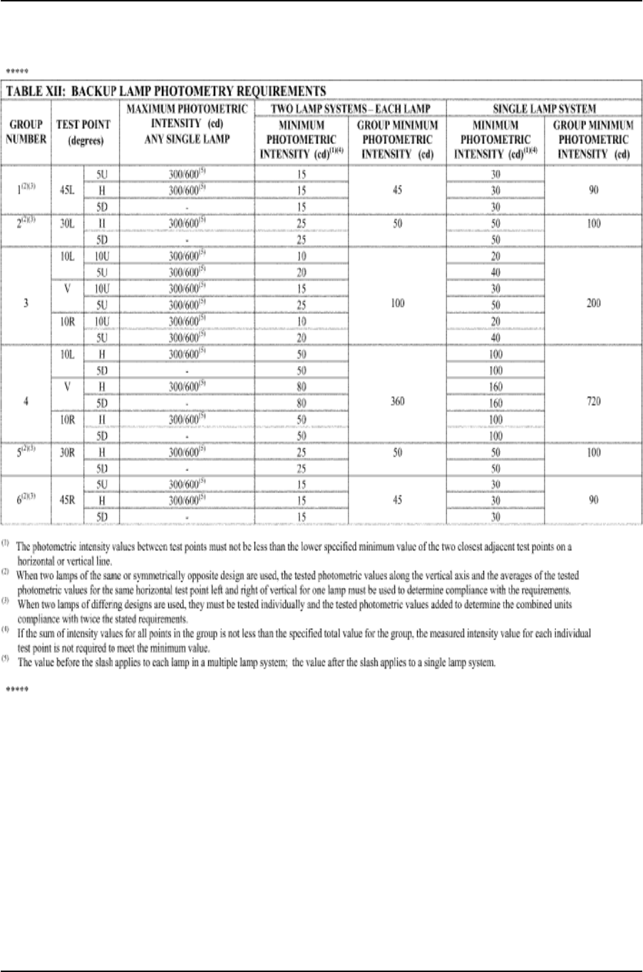
Lamps, Reective Devices, and Associated Equipment
124
Table XII—Backup Lamp Photometry Requirements
Effective:
February 04, 2021
TSD No. 108, Revision 7


Lamps, Reective Devices, and Associated Equipment
127
Table XIV—Parking Lamp Photometry Requirements
Effective:
February 04, 2021
TSD No. 108, Revision 7

Lamps, Reective Devices, and Associated Equipment
128
Table XV—High Mounted Stop Lamp Photometry
Requirements
Effective:
February 04, 2021
TSD No. 108, Revision 7

Lamps, Reective Devices, and Associated Equipment
129
Table XVI-a—Reex Reector Photometry
Requirements
Observation
angle
(degrees)
Entrance
angle
(degrees)
Minimum performance
Red reectors Amber reectors White reectors
(cd/incident
ft-c)
(mcd/lux)
(cd/incident
ft-c)
(mcd/lux)
(cd/incident
ft-c)
(mcd/lux)
0.2 0 4.5 420 11.25 1050 18 1680
— 10U 3.0 280 7.5 700 12 1120
—
10D
(1)
3.0 280 7.5 700 12 1120
— 20L 1.5 140 3.75 350 6 560
— 20R 1.5 140 3.75 350 6 560
1.5 0 0.07 6 0.175 15 0.28 24
— 10U 0.05 5 0.125 12.5 0.2 20
—
10D
(1)
0.05 5 0.125 12.5 0.2 20
— 20L 0.03 3 0.075 7.5 0.12 12
— 20R 0.03 3 0.075 7.5 0.12 12
(1)
Where reex reectors are mounted with their axis of reference less than 750 mm above the
road surface, photometry requirements below 5° down may be met at 5° down rather than at the
required specied downward angle.
Table XVI-b—Additional Photometry Requirements
for Conspicuity Reex Reectors
Observation angle
(degrees)
Entrance
angle
(degrees)
Minimum performance
Red
(mcd/lux)
White horizontal
orientation
(mcd/lux)
White vertical
orientation
(mcd/lux)
0.2 0 300 1250 1680
— 20L TO 20R — — 560
— 30L TO 30R 300 1250 —
— 45L TO 45R 75 300 —
— 10U TO 10D 1120 — —
Effective:
February 04, 2021
TSD No. 108, Revision 7

Lamps, Reective Devices, and Associated Equipment
130
Table XVI-c—Retroreective Sheeting Photometry
Requirements
Observation
angle
(degrees)
Entrance
angle
(degrees)
Minimum performance
Grade dot-C2 Grade dot-C3 Grade dot-C4
White Red White Red White Red
(cd/lux/sq
m)
(cd/lux/sq
m)
(cd/lux/sq
m)
(cd/lux/sq
m)
(cd/lux/sq
m)
(cd/lux/sq
m)
0.2 −4 250 60 165 40 125 30
— 30 250 60 165 40 125 30
— 45 60 15 40 10 30 8
0.5 −4 65 15 43 10 33 8
— 30 65 15 43 10 33 8
— 45 15 4 10 3 8 2
Effective:
February 04, 2021
TSD No. 108, Revision 7

Lamps, Reective Devices, and Associated Equipment
131
Table XVII—School Bus Signal Lamp Photometry
Requirements
Test point
(degrees)
Minimum photometric intensity (cd)
(2)
red
lamps
Minimum photometric intensity (cd)
amber lamps
5U: — —
20L 150 375
10L 300 750
5L 300 750
V 300 750
5R 300 750
10R 300 750
20R 150 375
H: — —
30L 30 75
20L 180 450
10L 400 1000
5L 500 1250
V 600 1500
5R 500 1250
10R 400 1000
20R 180 450
30R 30 75
5D: — —
30L 30 75
20L 200 500
10L 300 750
5L 450 1125
V 450 1125
5R 450 1125
10R 300 750
20R 200 500
30R 30 75
10D:
(1)
— —
5L 40 100
V 40 100
5R 40 100
(1)
Where school bus signal lamps are mounted with their axis of reference less than 750 mm
above the road surface, photometry requirements below 5° down may be met at 5° down rather
than at the specied required downward angle.
(2)
The photometric intensity values between test points must not be less than the lower specied
minimum value of the two closest adjacent test points on a horizontal or vertical line.
Effective:
February 04, 2021
TSD No. 108, Revision 7


Lamps, Reective Devices, and Associated Equipment
133
Table XIX-a—Headlamp Lower Beam Photometry
Requirements
Effective:
February 04, 2021
TSD No. 108, Revision 7
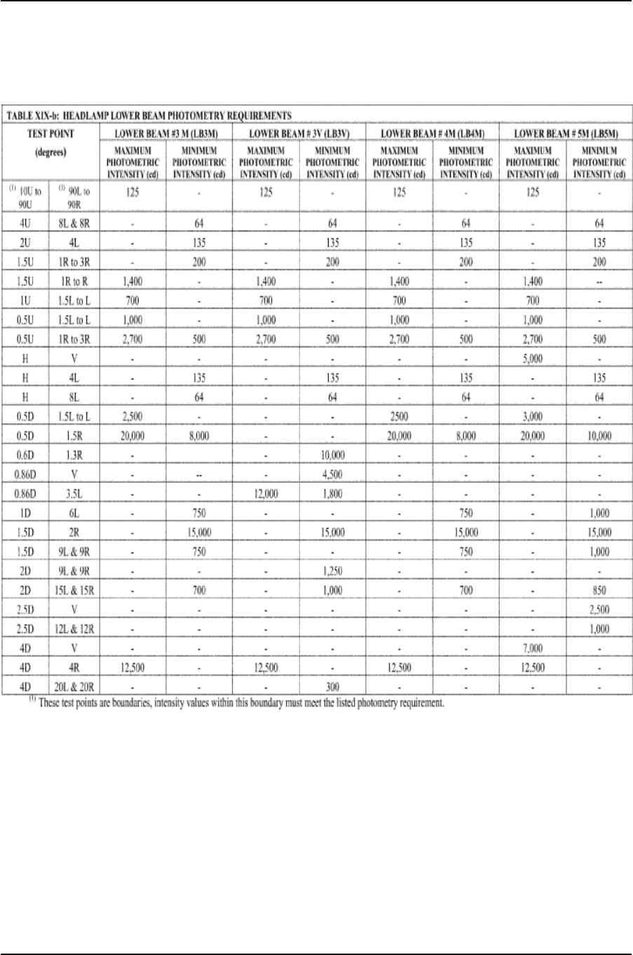
Lamps, Reective Devices, and Associated Equipment
134
Table XIX-b—Headlamp Lower Beam Photometry
Requirements
Effective:
February 04, 2021
TSD No. 108, Revision 7

Lamps, Reective Devices, and Associated Equipment
135
Table XIX-c—Headlamp Lower Beam Photometry
Requirements
Effective:
February 04, 2021
TSD No. 108, Revision 7


Lamps, Reective Devices, and Associated Equipment
151
Figure 14 — Type F: Headlamp Aim Deection Test
Setup
[CONTENT NOT REPRODUCED]
See SAE J1383, June 1990, Figure 7, for the applicable drawing.
Figure 15 — Types G and H: Headlamp Aim
Deection Test Setup
[CONTENT NOT REPRODUCED]
See SAE J1383, June 1990, Figure 8, for the applicable drawing.
Figure 16 — Types A and E: Headlamp Aim
Deection Test Setup
[CONTENT NOT REPRODUCED]
See SAE J1383, June 1990, Figure 5, for the applicable drawing.
Figure 17 — Type B: Headlamp Aim Deection Test
Setup
[CONTENT NOT REPRODUCED]
See SAE J1383, June 1990, Figure 6, for the applicable drawing.
Figure 18 — Types C and D: Headlamp Aim
Deection Test Setup
[CONTENT NOT REPRODUCED]
See SAE J1383, June 1990, Figure 4, for the applicable drawing.
Effective:
February 04, 2021
TSD No. 108, Revision 7


