
Quick Start
Juniper Apstra Freeform - 4.2.1
IN THIS GUIDE
Introducon to Apstra Freeform | 1
Reference Designs | 2
Freeform Overview and Design | 3
Freeform Resources | 23
Enable Resource Allocaon | 25
Resources in Jinja | 32
Deploy Modes | 36
Commit Check of Device Conguraons | 38
Jinja Support in Cong Templates | 41
Telemetry and IBA | 47
Pung It All Together | 48
Introducon to Apstra Freeform
SUMMARY
This topic introduces you to the following basic constructs
Apstra Freeform uses: Tags, Device Contexts, Property Sets,
and Cong Templates. We'll also create a simple Freeform
blueprint, and explore how to use Freeform with a number of
advanced case studies.
IN THIS SECTION
Introducon | 2

Introducon
Juniper Apstra is a powerful automaon and operaons soluon that manages the enre data center switching fabric’s
life cycle. This life cycle consists of the design, deployment, and operaonal phases of a network's life span. Apstra's
Intent-Based Networking (IBN) approach helps network architects and operators automate data center network design,
build, deployment, and validaon. This is accomplished by translang high-level business requirements (called "intent")
into an operaonal data center network.
The IBN approach provides a framework for managing complex networks using reference designs and stateful
orchestraon. The Apstra architecture and reference designs provide signicant benets, solving some of the most
dicult data center networking issues:
• Helps operators deal with change reliably. This is possible through real-me query-able intent and operaonal
context
• Simplies all aspects of the network service life cycle, including Day 0, 1, and 2 operaons, reducing the likelihood of
human error
• Reduces operaonal risk through stateful orchestraon, which leverages precondion validaons, post-condion
validaons, automated conguraon rendering, and automated expectaons validaon
Apstra lets you focus on scale and funconality while the system manages the low-level device conguraon and
operaon. Designers input specicaons via the Apstra user interface, where they are applied to the reference design
and retained in a graph database. The specicaons serve as the intended funconality of the network and are the
Single Source of Truth (SSOT) for network expectaons. Apstra provides operaonal assurance by performing a
connuous comparison of this model to the current state of all aspects of the network.
Reference Designs
IN THIS SECTION
Apstra Reference Designs | 2
Apstra Reference Designs
Apstra currently provides reference designs for 3 and 5-stage Clos fabrics, along with a collapsed fabric model for
smaller/edge environments. Apstra provides virtualized overlay funconality via support of VXLAN encapsulaon and
an EVPN control plane. The architectural details of these reference designs are based on industry-recognized best
pracces, making them applicable to most data center design scenarios. However, there are situaons where design
2

exibility is required beyond what is praccal with these models. The Apstra team has introduced Freeform to address
these design situaons.
Being the latest addion to reference designs in the Apstra soluon, it diers from the exisng models in that control of
all design elements is placed enrely into the architect's hands. Networks designed with Freeform are not restricted to
the exisng design frameworks in the Apstra data center reference designs. However, Freeform sll takes advantage of
the Apstra soware architecture, as explained throughout this document. It is important to note that unlimited design
exibility comes with inevitable trade-os, primarily around the abstracted and automated user experience.
Apstra reference designs are purpose-built frameworks for capturing the architect's intent. The reference designs
govern:
• The roles and responsibilies of physical and logical components (funconality, scale, interconnecvity)
• How services are mapped to enforcement mechanisms
• The expectaons that need to be met (i.e., situaons to monitor)
This structured approach results in a system that not only assures awless conguraon, but provides unprecedented
control, visibility, and validaon of the infrastructure. Signicant eciencies are gained by this approach, including the
eliminaon of conguraon mistakes.
Freeform Overview and Design
IN THIS SECTION
Freeform Reference Design Overview | 4
Blueprints | 4
Blueprint Import/Export | 5
Topology | 7
Colors | 9
Tags | 9
Creang Systems | 9
Creang Links | 11
Link Aggregaons (LAGs) | 11
Device Proles | 14
Execute CLI Commands | 15
Cong Templates | 17
Nesng (Composable) Cong Templates | 17
Rendering Order | 19
3

Property Sets | 19
Data Structures in Property Sets | 21
Freeform Reference Design Overview
A Freeform reference design diers from the other reference designs in that the network designer is responsible for
creang and validang all device conguraons. Any feature, protocol, or architecture that ts the deployment scenario
can be leveraged. Devices and links are modelled in a topology editor, which creates objects represenng the reference
design in the graph database. As with the other reference designs, Freeform sll leverages the context graph, Intent-
Based Analycs (IBA), conguraon validaon, network operang system (NOS) management, Time Voyager, and
numerous other Apstra soware features. When compared to the more advanced reference designs however, reduced
depth of IBA capabilies is the trade-o for greater design exibility.
Freeform consists of various design and build elements and views that each manage specic network design aspects.
Their funcon and usage are described in the following secons.
Blueprints
When creang a new network with Freeform reference design, you start by creang a Blueprint. As with the other
reference designs, the Blueprint contains all elements associated with an operang network managed by Apstra, but
there are a few key dierences in how Blueprints are structured and used in Freeform.
The Data Center reference designs require design and build elements such as logical devices, interface maps, racks, and
templates. These steps are unnecessary in a Freeform design because you create conguraon details and device links
directly into the Blueprint. When creang a new Blueprint, you simply select the Freeform Reference Design, as shown:
4

Blueprint Import/Export
You can import and export Freeform Blueprints into and out of Apstra. This allows you to simplify the migraon of
blueprints from one Apstra instance to another. This feature can also be ulized to create a “catalog” of Freeform
reference designs. An engineer might use this catalog to standardize a network design by taking the informaon from
the blueprint and implemenng it as a standardized design for many Apstra implementaons. These implementaons
could funcon as templates or models of a design that is used by an organizaon in mulple geographic locaons,
enabling fast, uniform deployments of custom network designs at scale. Another use case for this feature is the tesng
or evaluang of dierent network designs and systems. Examine various aspects of the imported/exported Blueprint
without the commitment of a full deployment. All of these possibilies exist in Apstra Freeform.
To Export a Blueprint follow this simple workow:
You can then choose what elements of the Blueprint you would like to Export, as shown below. If all of the toggles are
“o,” only the contents of the topology editor (discussed in the next secon) are exported.
5

Aer the export is complete, the blueprint is saved in JSON format for use.
Imporng a Blueprint is similar; simply create a new Blueprint and click on the import dialog, then select the Blueprint
you want to import.
6

Topology
Aer creang a new Freeform Blueprint, you can begin designing your network topology. As with the DC Reference
Architectures, all design work is done from the Staged Blueprint tab. The Staged topology editor area in Freeform is
where you interact with the elements to create your network design and architecture. The topology editor is a new
capability in Freeform that allows you to create bespoke network designs in an interacve manner. You can select
networking devices and connect them interacvely by dening links between them. These devices can be internal or
external.
7

Internal devices are managed by Apstra and must be mapped to device proles that model device capabilies and
interact with devices using agents. External devices are not directly under the Apstra management umbrella, but can sll
be modelled in the topology view in order to simulate interacons with internal devices. For example, you can simulate
interface links and speeds. External devices do not ulize device agents or models.
You can create single, mulple, or even aggregated links between devices. You can interact with the topology to re-
arrange the design layout, add links, and edit colors or tags for devices and links. You can perform Create, Read, Update,
8

and Delete (CRUD) operaons by selecng the system's gear icon. You have the opon to perform CRUD operaons for
both individual objects and objects in bulk.
Colors
You can use colors to create quick visual groupings and disncon between Apstra devices. For example, devices
connecng to rewalls can be red while devices doing IP-Forwarding only can be orange.
Tags
In Apstra, Tags are a powerful feature. Tags are a way for you to assign metadata to Apstra-managed resources. These
Tags can help you idenfy, organize, search for, and lter Apstra resources. Tags are also useful to help you categorize
resources by purpose, owner, environment, or other criteria. Because Tags are metadata, they are not just used for
visual labeling, but also applied as a property of the node in the Apstra graph database. This node property, or device
property, is then available for you to reference in Jinja for dynamic variables in cong generaon and the Apstra real-
me analycs via Apstra's Live Query technology and Apstra Intent-Based Analycs.
For example, you can use tag `firewall` to output a specic descripon:
{% if has_tag(interface.link.neighbor_system.id, 'firewall') %}
description "this is a firewall facing interface";
{% endif %}
For more examples of how to access and use tags, see the "Accessing Values in The Device Context" on page 41 and
"Jinja Support" on page 41 secons.
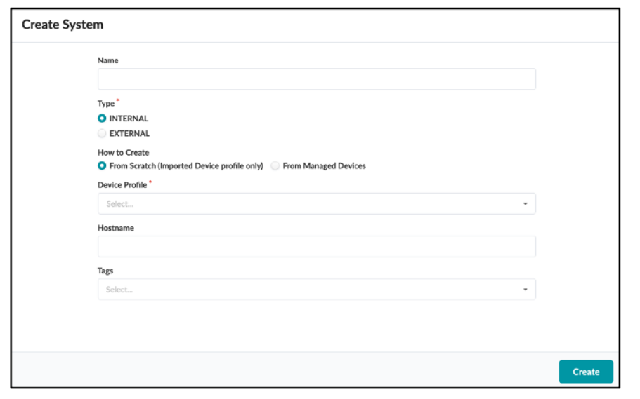
Creang Systems
There are two ways to create a new System:
9

1. Navigate to Staged > Topology > Topology Editor.
Use the rst two icons in the boom menu to create either an internal or an external system. The new system will
appear in the topology view. When creang an internal system, you can oponally specify which Device Prole to use
and assign a System ID. See how to create and import Device Proles into the Blueprint in the Device Proles secon.
2. Navigate to Staged > Systems.
This method automacally adds the new systems in the Topology view.
You can choose to create a new system from an exisng managed device or create a new system with a specic device
prole and assign a managed device later once the equipment is ready and part of the Apstra managed devices.
10
Creang Links
You can use links to connect objects or devices together. Links are single or aggregate links. These links can have
parameters assigned to them via the topology editor "gear" icon. The links can have IP addresses and tags assigned.
Link Aggregaons (LAGs)
Links can be a Link Aggregaon, or LAG. Access the LAG eding area by selecng the Topology view, then selecng a
device, then selecng the Manage LAGs icon.
11

The following is a view of the Link aggregaon user interface.
12

Select two links to form an aggregate. The changes display aer clicking Aggregate.
Click Apply Changes to update the topology editor with the new LAG. The aggregate link is thicker and colored blue.
13

Link & LAG management simplies the potenally complex process of managing the dierent permutaons of link
setups.
Device Proles
Device Proles dene the capabilies of supported hardware devices. Some feature capabilies have dierent
behaviors across NOS versions. Certain capabailes might perform dierently depending on your NOS version.
NOTE: In the inial versions of Freeform, only Device Proles for Juniper Networks devices are supported.
Before you can create a Blueprint, you must import Device Proles into the Blueprint. You can then use those devices in
the topology editor of the Blueprint.
14

Execute CLI Commands
Users might want to interact with the devices in your network directly via CLI for funcons like stascs display, or to
check device status or interface health. Apstra Freeform simplies CLI access. Considering the range of devices that
might make up a network, this feature is more useful than ever in custom Freeform topologies. To access the CLI
command funconality, navigate to the device and you will see the following dialog:
Click on the
Execute CLI Command eld. A CLI eld displays for CLI commands. Typing part of a command displays a
prompt containing all available related commands within the CLI structure.
NOTE: Only show commands are currently supported.
15

NOTE: Use the Tab key to auto-complete your command to the next hierarchical level.
The following is an example output from the CLI command. You don't have to open a terminal session and SSH into the
device to view outputs. Aside from the text output in this example, you can also select XML or JSON output formats.
16
Cong Templates
Since the design of the network elements in Freeform is arbitrary, the device conguraons are not automacally
rendered by the Freeform reference design; rather, you have complete control of the conguraon of your devices.
Beginning in Apstra 4.1.1, we introduce the concept of a Cong Template specically for Freeform to drive device
conguraon. Cong Templates can be very simple and stac to very complex and programmac, depending on the use
case and level of automaon you are comfortable with. Cong Templates support using Jinja2 template language, which
can oponally interact with the device context and property sets.
Nesng (Composable) Cong Templates
As Cong Templates support Jinja templang, a powerful nesng feature is supported that enables you to include a
secon of a cong template from the list inside of another cong template. There are two main benets of nesng
cong templates. The rst is that with nesng, you can separate various services, conguraon secons, etc. out to
common components and create dedicated cong templates for them.
For example, assume that you have a base system stanza conguraon for banners, logins, NTP, etc., for most of your
Juniper devices. Instead of copying and pasng the same conguraon into each of your device templates, you can
create a dedicated cong template for the base system cong. Then, simply reference that template from within another
template.
The second benet is that you only need to link one cong template to a device. That device automacally inherits all
conguraon sengs of any linked templates.
As an example, the following cong template, junos_configuration.jinja, is a single cong template with several nested
cong templates, such as junos_system.jinja and junos_interfaces.jinja. You only need to link the junos_configuration_jinja
template to device bond-street and all nested cong templates are applied.
17

In the following image, the junos_system.jinja only renders the system hostname (bond-street) of it's parent template:
18

Rendering Order
Apstra renders the conguraon according to the order of the cong template.
Property Sets
Property sets are collecons of key-value pairs that you import into Blueprint catalogs to use in Cong Templates and
IBA probes. The use of property sets is oponal, but it provides a valuable capability that allows you to fully
parameterize Cong Templates by separang the persistent sengs of the Cong Template from the actual variables. In
other words, property sets enable a more granular control of the Device Model used to render conguraons arbitrarily
and exibly.
For example, the conguraon of NTP on all devices in the enterprise may be consistent, but with diering me sources
or strata per geography. You can create an NTP cong template using a dierent variable for each geographic locaon.
For example, you can use the property named "ntp".
19

NOTE: It’s important to use the correct syntax, and remember that key values are case sensive.
In this case you can create the Cong Template with {{ntp}} instead of the IP address of NTP server. This Cong
Template is imported into all Blueprints, but Blueprints running in the East region have the “EAST” property set
imported, and Blueprints running in the West region have the “ WEST” property set imported. Property sets are globally
scoped by default.
Freeform also supports property sets that are assigned to a specic device. This enables you to create specic property
sets and assign them to certain devices. Apstra stores property sets in a graph database where their values can be used
in IBA probes.
The following examples show that you can access property sets via the Device Context tab or the Graph visualizer.
20

Data Structures in Property Sets
Freeform property sets support advanced data structures that you can use to fulll dierent use cases. Freeform
Property Sets support any of the typical Python data types, including:
21
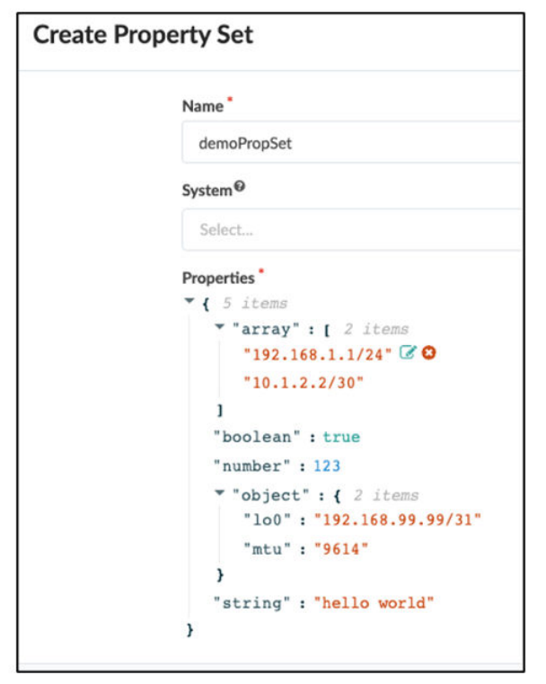
• Arrays (list of items)
• Boolean: True or False
• Integers: 1, 2, 3 etc.
• Float: 1.2, 3.65, etc.
• String: “Hello World”
• Diconary: {“asn”: 65432, “lo0”: “1.2.3.4/32”}
You can reference the Property Set globally or assign it to a System in the Blueprint.
22

In the example above, you can recurse the diconary using the keys and use the keys as values as required:
• esxRedTrunk is the link tag name to be used as an interface descripon
• 99, 100, 101 are the VLAN ID / trunk members & irb.<value> to be assigned
• subnet / descripon / gateway are also used to derive meaningful conguraon
Freeform Resources
IN THIS SECTION
Understanding Resources in Apstra | 24
Types of Resource Objects | 24
The Importance of Scope, and the Graph | 25
Example Graph Queries | 25
23

Groups | 25
Group Generators | 25
Understanding Resources in Apstra
Resources are objects/items in Freeform that can be assigned as part of your network design. They can be anything
from IP addresses to a simple integer. Resources can be either stacally dened or allocated from a pool of resources.
You might think of a resource like an object in an IP Address Management (IPAM) system, or a Dynamic Host
Conguraon Protocol (DHCP) scope. In such cases, you dene the scope, and objects are created dynamically within
that scope such that a single object is only used once and then returned to the object pool for re-use. The same
concepts apply to Generated Resources in Apstra Freeform.
Types of Resource Objects
There are several types of resource objects in Freeform:
• Allocaon Groups: Dene the type of resource and the pool from which you allocate resources. Resource generators
use these groups to create resources.
• Pools: Dened containers of resources that you can allocate. These pools have a specic type associated with them,
such as IP address or ASN.
• Local Pools: Objects that are pools but are assigned to a node (system). The pools can only be of type VLAN.
• Local Pool Generator: A resource that is generated dynamically from a graph scope but is assigned as a resource to a
system. The pools can only be of type VLAN.
• Resource: A single instanaon of an object you want to create and use in your design. An example of a resource
would be a single IPv4 address, such as 192.168.1.24.
• Resource Generator: An automaon object consisng of parameters including a graph scope, and a type (IPv4
address, IPv6 address, Integer, ASN). This object generates resources for use in your design. Resource Generators
live in Resource Groups.
• Resource Groups: An object that contains resources and resource generators. Resource groups can be used to
organize your environment as it becomes increasingly complex. At least one group must be allocated. Note that
there is a default group called Root, but that group is unusable for resource objects other than Groups.
• Group Generators: An object that creates resource groups dynamically based on a dened scope. The group
generator scope is set based on a graph query. This query creates dynamic groups based on the query response.
Every element created under this group inherits this scope.
24
The Importance of Scope, and the Graph
Resource Generators and Group Generators are both based on a scope. A scope is a query to the graph database that
returns a set of objects. The generator then generates a resource based on the objects that are returned. It’s important
to understand that scopes can use ltering mechanisms - such as idenfying tags and the type of object (link or system)
- to generate resources based on the scope.
Example Graph Queries
• All of the internal systems node ('system', system_type='internal', name='target')
• All of the links to external systems node ('link', role='external', name='target')
•
Internal links marked with tag of "fabric" node ('link', role='internal', tag='fabric', name='target')
Groups
Apstra uses Groups like folders in order to group together resources and resource generators. A default "Root" is
automacally created. This group is the Group that houses all other groups. You must rst create a Root group in order
to generate resources for other groups. Create a Root group if necessary, create a new group housed within the Root
group, and generate the necessary resources.
Group Generators
Group generators generate groups dynamically in order to assist with the management of resources. These dynamically-
created groups are created based on a graph query scope, as shown previously with the resource generators node
('link', role='internal', name='target'). The upcoming example walks through managing the resources for each system in
your network, including a Loopback IP address and an ASN number for BGP peering. We use a scope graph query to
select all the systems and create a group for each system. This ensures that the Loopback IP and ASN for the specied
system are housed within that system’s group.
Enable Resource Allocaon
25

This topic outlines the steps required to enable resource allocaon. Follow these steps to allocate resources and their
associated objects. Then, congure these resources in Jinja.
1. Create a resource pool object. To create a resource pool, select the Resources icon on the le side of the page.
You must create a resource pool which acts as a countainer for other resources. The available opons are:
• ASN Pools
• VNI Pools
• Integer Pools
• IP Pools
• IPv6 Pools
2. Create an Allocaon Group. Allocaon Groups are located within the Blueprint interface under Staged > Resource
Management > Allocaon Groups
An Allocaon Group lets you allocate resources to be used in a resource generator. With Allocaon Groups, you can
group mulple resource pools together in a single enty.
26

Select one or mulple allocaon groups for detailed informaon like Parameters, and associated Resources and
Resource Generators.
27

3. Create a Group.
Aer you group resource pools into an allocaon group, you can create a resource Group. Resource Groups contain
resources and resource generators. Note the default "root" group. This group only contains other groups, not pure
resources.
4. Create a Stac Resource.
Create a Stac Resource if you want to assign the resource value stacally. Stac Resource values do not change.
Stac Resources enable you to set resources that won't change over me. The following example shows the creaon
of a Stac Resource of type integer, with a value of 190.
28

5. Create a Resource Generator.
Resource Generators are automaon objects that generate resources like IP addresses and ASN pools for your
network design. Resource Generators reside within Resource Groups. Resource Generators require a graph query
scope that denes how many resources the generator automacally creates.
The following example shows the creaon of a Resource Generator with name asn_generator, of type ASN within the
ASN_alloc_group.
29

6. Create a Group Generator.
Group Generators are objects that create Groups based on a dened scope. Groups created by a Group Generator
inherit the scope of the Group Generator. This enables you to create specic Resource Generators within a Group
Generator, which lets you automacally allocate resources and properly group those resources into Groups.
For example, you can create a Group Generator for each internal system in your network. These internal systems
might need a respecve loopback address and an ASN Number. If you create a Group Generator that includes those
Resource Generators, the Group Generator automacally creates the Group for each internal system. The ASN and
loopback addresses are created and organized within those internal Groups.
30

The following example shows a Group Generator with name system-instance, and a dened scope.
31

Resources in Jinja
SUMMARY
This topic provides informaon about how Jinja uses and
interacts with Apstra Freeform resources. Use Jinja with
Freeform to create, edit, and update custom Cong Templates
in real me.
IN THIS SECTION
Examine Resources in Jinja | 32
Use a Resource in Jinja | 33
Use the Built-In Funcon for Resources | 34
Create a Resource Generator | 35
Examine Resources in Jinja
The Cong Template editor features a three-pane interface for interacng with generated resources. Apstra Freeform
utlizes the Jinja code to nd and include designated resources from the resource tree.
32

Use a Resource in Jinja
Aer you create Resources in the Blueprint, these resources can be accessed via the Device Context.
The following example shows how to use Jinja to include a funcon to get the resource value for a resource called
'ipv4_loopback' inside the resource group structure called 'underlay':
{% set loopback_ipv4 = function.get_resource_value(resources, 'ipv4_loopback', 'underlay') %}
33

Use the Built-In Funcon for Resources
Apstra includes useful built-in funcons that we recommend you use in Jinja creaon. These funcons are documented
inside the user interface. To access the funcon documentaon, use the built-in editor in Jinja to access the
documentaon page via the UI. The link to the documentaon is the Apstra server UI: hps://<apstra_ip>/stac/
jinja_docs/ for reference.
34

Create a Resource Generator
Follow these high-level steps to create and use a Resource Generator:
1. Crete a Resourde Pool
2. Create an Allocaon Group
3. Create a Resource Group under the default "root" Group
4. Create a Resource Generator
5. Use Resource in Jinja
35

Deploy Modes
IN THIS SECTION
Freeform Deploy Modes | 36
Freeform Deploy Modes
In typical Data Center Blueprints, you can set the Deploy Mode of systems in Freeform. The available opons are:
• Deploy
• Ready
• Drain
• Undeploy
However, in Freeform, you can dene the conguraon rendered when a system is in each mode.
You can use the Deploy Mode to condionally render dierent conguraons, such as whether to render roung
protocol sessions or to indicate how parcular route maps would render on a device. For example, if the device was set
to “Drain” it would have specic Jinja to generate a conguraon that removed the dynamic roung protocols.
The Deploy Mode of a system is exposed to the user in the Device Context, referenced in Cong Templates as Jinja
variables:
36

The Deploy Mode of neighboring systems are also available.
Changing the Deploy Mode of a system has no eect on the rendered conguraon if it has not been referenced by the
Cong Template assigned to the system.
An example of how this could be accomplished in a Jinja Cong Template is as follows:
{% if deploy_mode in ['deploy', 'drain'] %}
{% include 'protocols.jinja' %}
{% include 'policy_options.jinja' %}
{% endif %}
In this example, both the protocols.jinja and policy_options.jinja become acve when a given node is in either the ‘deploy’
or ‘drain’ state. The behavior can be modied to suite individual needs.
37

Commit Check of Device Conguraons
IN THIS SECTION
Conguraon Check | 38
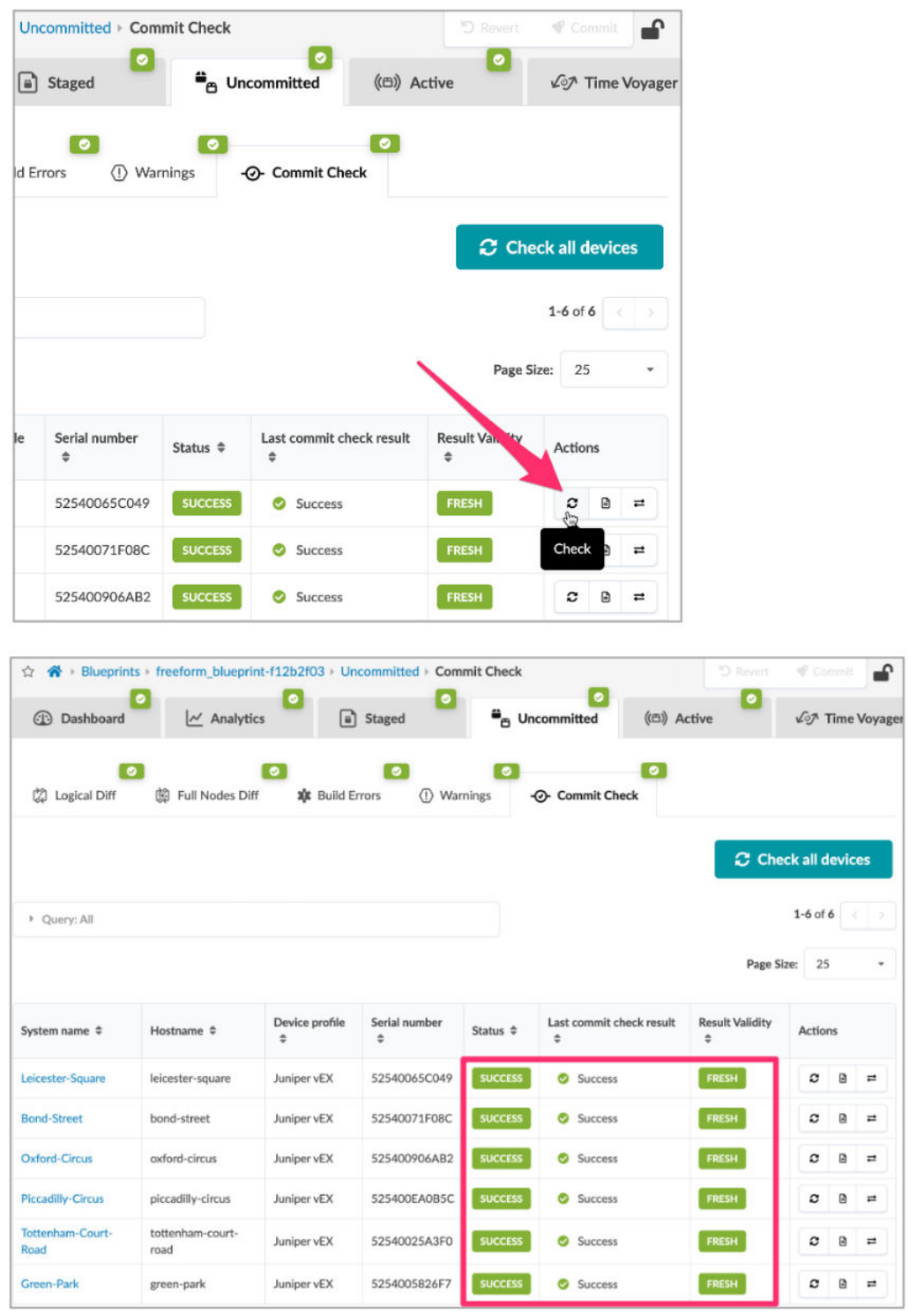
Conguraon Check
Apstra provides a funcon to perform a Junos conguraon check for all devices in a Blueprint from a simple user
interface. This cong check funconality is based upon the built-in funconality of Junos; it uses the devices cong
check ulity to check the conguraon before it is commied to see if there are any errors in the conguraon. Cong
check is viewed from the Uncommied area of the Blueprint.
38
Note that the devices are listed with their Status and Result Validity; you can then perform the “Check All Devices” or
check a single device.
39
40

The results are straighorward and can be used before comming the changes to ensure that the cong is properly
commiable.
Jinja Support in Cong Templates
IN THIS SECTION
Using Jinja in Cong Templates | 41
Accessing Values in the Apstra Device Context | 41
Examples of Using Jinja in Cong Templates | 43
Building and Tesng Your Cong Templates with Jinja | 46
Mul-Pane Cong Template Editor | 46
Using Jinja in Cong Templates
As previously menoned, Cong Templates support the use of Jinja template syntax. You can use Jinja2 template
language to interact with the Device Context and Property Sets features. This allows for a high degree of automac
template evaluaon and rendering of the end device conguraon. Using Device Context properes with Jinja syntax
essenally serves to have dynamically-built values for Cong Templates based on the Apstra Single Source of Truth
(SSOT) database.
This is useful for use cases where you want to apply the Cong Template to many switches or interfaces with
parameterized values, or if you want the Cong Template to include dynamic data (such as the switch's own Hostname)
from the Blueprint.
Accessing Values in the Apstra Device Context
There are several dierent ways for you to view all of the key values Apstra stores for each device.
You can select Device Context in either the Staged or Acve topology view by navigang to an internal node. The
Device view displays by default:
41

You can also interacvely view Device Context while creang a Cong Template:
42

Finally, you can also access the Device Context via API:
<apstra-ip>/api/blueprints/<bp-id>/nodes/<system-node-id>/config-context
Use the Blueprint UI to access the required data for the API call. Select the device and note the Blueprint ID and node
ID in the URL:
Examples of Using Jinja in Cong Templates
Hostname
The following example shows a stac secon of a Junos Cong Template. A single Jinja template references a device's
hostname variable, which is replaced by the value stored in the Apstra graph database. The value is passed in when the
template is rendered. This use of Jinja and variables is helpful when creang dynamic data from Apstra.
43

BGP ASN From Device Context
Similar to the previous example, the following example shows how you can call a key value of a device property. The key
value is stored in the Apstra graph database in order to build conguraons dynamically. Here, the keys bgpService.asn
and bgpService.router_id are replaced by the values stored by Apstra and are passed in when the template is rendered:
router bgp {{ bgpService.asn }}
{{ bgpService.router_id }}
Resulng Rendered Conguraon:
router bgp 64512
10.0.0.2
44

Dening Variables for Use in Loops
In some cases, it might be useful to dene and store variables directly in the Cong Template. Apstra refers to these
variables when rendering your conguraon. The following example shows how you can create an access-list using
dened variables.
{% set bgp_filters = {
'flb': {
'in': ('permit', '10.0.0.0/8'),
'out': ('deny', '6.6.0.0/16'),
}
} %}
{% for types, entries in bgp_filters.items() %}
{% for direction, entry in entries.items() %}
ip prefix-list BGP-vm-{{ direction }}-filter seq 1000 {{ entry.0 }} {{ entry.1 }}
{% endfor %}
{% endfor %}
Resulng Rendered Conguraon
ip prefix-list BGP-vm-in-filter seq 1000 permit 10.0.0.0/8
ip prefix-list BGP-vm-out-filter seq 1000 deny 6.6.0.0/16
Property Sets and Jinja Loops
You can also use Jinja to loop over and evaluate a data model from a Property Set containing a list of elements. Consider
the following Simple Network Management Protocol (SNMP) conguraon example. Note that you can combine values
in a Property Set with a Jinja for loop to render a nal conguraon with mulple dynamic lines of cong.
ip access-list SNMP_RO
{% for server in snmp_servers.split(',') %}
permit ip host {{server}} any
{% if loop.last %}
exit
{% endif %}
{% endfor %}
snmp-server source-interface traps loopback 0
snmp-server community tempPassword group network-operator
snmp-server community tempPassword use-ipv4acl SNMP_RO
{% for server in snmp_servers.split(',') %}
snmp-server host {{server}} traps version 2c mypass
{% endfor %}
45

Property Set:
Resulng Rendered Conguraon
ip access-list standard SNMP_RO
permit host 203.0.113.100
permit host 203.0.113.101
exit
snmp-server source-interface loopback 0
snmp-server community tempPassword view mysystem ro SNMP_RO
snmp-server enable traps snmp authentication
snmp-server host 203.0.113.100 traps version 2c mypass
snmp-server host 203.0.113.101 traps version 2c mypass
Building and Tesng Your Cong Templates with Jinja
Freeform also oers a mul-pane Cong Template editor. This innovave feature funcons similarly to an Integrated
Development Environment (IDE) for building and eding Cong Templates in real me.
Mul-Pane Cong Template Editor
Template Text Pane
As the name suggests, the mul-pane Cong Template Editor features several eding windows. The main window is the
Template Text
area, where you build the Cong Template. This
Template Text
area supports syntax highlighng,
autocomplete, and error nocaon.
46

Preview Pane
The next window is a
Preview
pane which processes any included Jinja syntax and renders the nal Cong Template
compilaon. This allows you to view the nal processed conguraon in real-me. You have a choice of viewing the
complete cong or the incremental cong.
Device Context Pane
Lastly, a
Device Context
pane provides you with all of the graph properes Apstra has available for the selected device.
This lets you quickly see and search for values you can use in your Cong Templates for dynamic variable substuon.
NOTE
: In order for the preview pane to successfully show the rendered cong from your Jinja template, you
must have the Jinja template loaded and aached to the device you are tesng it against.
Telemetry and IBA
IN THIS SECTION
Acve Anomaly Detecon and Reporng | 48
47
Acve Anomaly Detecon and Reporng
Freeform oers constant, automated monitoring of key aspects of the acvely deployed system in the network.
Freeform monitors aspects - or anomalies - such as trac anomalies, interface anomalies, and deviaons between the
congs and the deployed network. Anomalies are dynamically evaluated as your network runs and operates from day-
to-day.
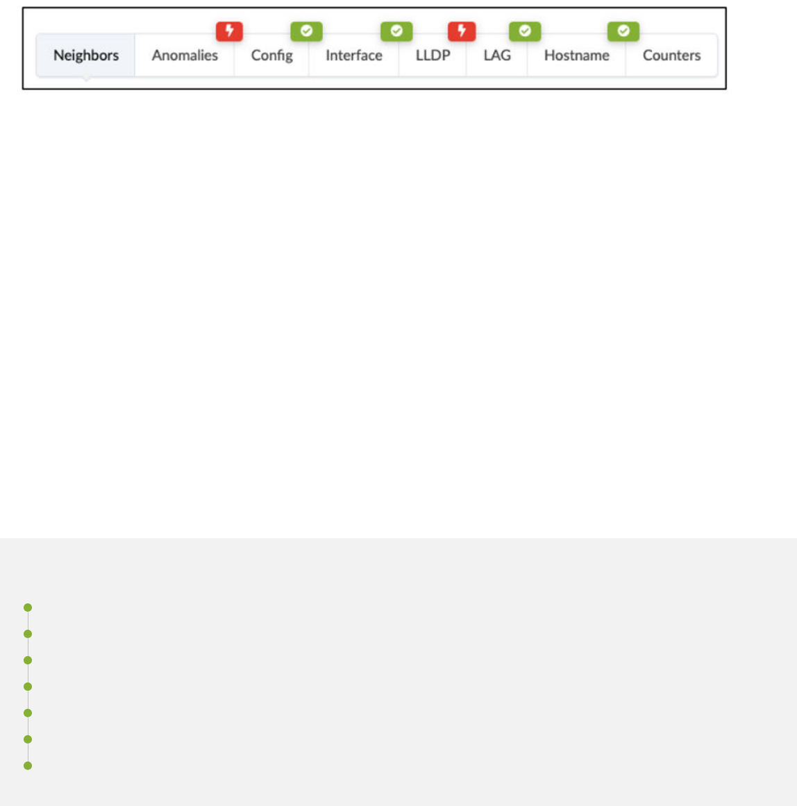
Monitored anomalies include the following categories:
• Neighbors: The list of neighbors connected to the device via the Graph
• Anomalies: Summary of any anomalies found on the device
• Cong: Any cong deviaons or problems
• Interface: Interface-focused anomalies (up/down etc.)
• LLDP: Anomalies focused on LLDP data to make sure it matches intent
• LAG: Anomalies in LAG groups and any issues
• Hostname: Any issues in the hostname
• Counters: List of counters for all interfaces and other informaon
Pung It All Together
IN THIS SECTION
Introducon | 49
Use Case 1: Small Version of London Tube (CloudLabs Topology) | 49
Rendered Conguraons for Use Case 1 | 50
Cong Templates | 52
Use Case 2: Tags and Property Sets to Drive Day-2 Conguraon | 56
Use Case 3: Advanced Example Using Centrally Routed Bridging (CloudLabs Topology) | 63
Summary | 67
48

Introducon
The following use cases are examples of dierent network designs that ulize dierent methods and techniques of the
Apstra Freeform features we’ve discussed. These examples are meant to help you beer understand how the features
of Apstra and Freeform are used to address various networking use cases.
Use Case 1: Small Version of London Tube (CloudLabs
Topology)
This use case uses a small version of the London underground system as a map to design a network topology from
arbitrary switches. The concept here is to create a simple network design using Jinja templates, and a Property Set. This
use case demonstrates how you can create a complete network design using straighorward Jinja templang and
Property Sets.
This use case is available as a hands-on lab using Juniper Apstra Cloudlabs (see the related links secon at the end of
this arcle for more informaon about CloudLabs). A GitHub repository includes the Jinja les and JSON Property Sets
you can reference, contribute to, or even fork.
The following image shows the topology of the environment for this use case.
In the following image, note that all system links show tags and IP addresses assigned via the topology editor/API:
49

Rendered Conguraons for Use Case 1
The following examples are rendered conguraons for the Bond-Street device in the topology.
The Interfaces Code Block:
interfaces {
replace: xe-0/0/0 {
unit 0 {
interfaces {
replace: xe-0/0/0 {
unit 0 {
description "facing_oxford-circus:xe-0/0/1";
family inet {
address 192.168.0.2/31;
}
}
}
replace: xe-0/0/1 {
unit 0 {
description "facing_green-park:xe-0/0/1";
family inet {
address 192.168.0.8/31;
}
}
}
replace: lo0 {
unit 0 {
family inet {
address 10.0.0.2/32;
}
The Policy-Opons Code Block:
policy-options {
policy-statement send-direct {
term 1 {
from protocol direct;
then accept;
}
}
policy-statement add-med-110 {
from {
route-filter 0.0.0.0/0 longer;
50

}
then {
metric add 110;
}
then {
accept
}
}
policy-statement add-med-177 {
from {
route-filter 0.0.0.0/0 longer;
}
then {
metric add 177;
}
then {
accept
}
}
}
The Protocols Code Block:
protocols {
lldp {
port-id-subtype interface-name;
port-description-type interface-description;
neighbour-port-info-display port-id;
interface all;
}
replace: rstp {
bridge-priority 0;
bpdu-block-on-edge;
}
bgp {
group external-peers {
type external;
export send-direct;
neighbor 192.168.0.3 {
peer-as 22;
export add-med-110;
}
neighbor 192.168.0.9 {
peer-as 86;
export add-med-177;
}
51

}
}
}
routing-options {
autonomous-system 47;
}
Cong Templates
The following are example Cong Templates for Use Case 1.
Cong Template system.jinja.
system {
host-name {{hostname}};
}
This is the main.jinja cong template. This template is the system.jinja template that uses the builn “hostname” variable
from the Device Context to set the system host-name.
Cong Template interfaces.jinja.
{% set this_router=hostname %}
interfaces {
{% for interface_name, iface in interfaces.iteritems() %}
replace: {{ interface_name }} {
unit 0 {
description "{{iface['description']}}";
family inet {
address {{iface['ipv4_address']}}/{{iface['ipv4_prefixlen']}};
}
}
}
{% endfor %}
replace: lo0 {
unit 0 {
family inet {
address {{ property_sets.data[this_router]['loopback'] }}/32;
}
}
}
}
52

Note the following:
• {% set this_router=hostname %}: Sets the variable this_router=hostname.
• {% for interface_name, iface in interfaces.iteritems() %}: A for loop that walks through the interfaces and inserts the
proper interface stanza syntax for Junos. This includes the descripon of the interface and the family inet address
and prex length from the device context. You can populate these values via the Links view in the Topology Editor.
• replace: lo0 { unit 0 { family inet { address {{ property_sets.data[this_router]['loopback'] }}/32; } }: This code inserts the
property_set data for this router’s loopback address into the loopback stanza.
Cong Template protocols.jinja.
{% set this_router=hostname %}
policy-options {
policy-statement send-direct {
term 1 {
from protocol direct;
then accept;
}
}
{% for interface_name, iface in interfaces.iteritems() %}
{% set link_med = iface.link_tags[0] %}
{#
this may create multiple identical policy-statements, but JunOS is smart enough
to squash them.
#}
policy-statement add-med-{{ link_med }} {
from {
route-filter 0.0.0.0/0 longer;
}
then {
metric add {{ link_med }};
}
then {
accept
}
}
{% endfor %}
}
protocols {
lldp {
port-id-subtype interface-name;
port-description-type interface-description;
neighbour-port-info-display port-id;
interface all;
53

}
replace: rstp {
bridge-priority 0;
bpdu-block-on-edge;
}
bgp {
group external-peers {
type external;
export send-direct;
{% for interface_name, iface in interfaces.iteritems() %}
neighbor {{ iface.neighbor_interface.ipv4_address }} {
{% set peer_hostname=iface.neighbor_interface.system_hostname %}
peer-as {{ property_sets.data[peer_hostname]['asn'] }};
export add-med-{{ iface.link_tags[0] }};
}
{% endfor %}
}
}
}
routing-options {
autonomous-system {{ property_sets.data[this_router]['asn'] }};
}
Note the following:
• {% set this_router=hostname %}: Sets the variable this_router = hostname from the device context.
• policy-statement send-direct { term 1 { from protocol direct; then accept; }: Sets a policy-options stanza to send to all
directly-aached routes.
• {% set link_med = iface.link_tags[0] %}: Sets the variable link_med to the tag associated with the interface via the
Topology.
• The lldp secon under protocols sets the Link Layer Discovery Protocol (LLDP) parameters.
•
The rstp secon under protocols sets the Rapid Spanning Tree Protocol (RSTP) parameters.
• group external-peers { under bgp: Group external-peers.
•
type external;: Sets the type (eBGP) of external policy.
• export send-direct;: Export policy of send-direct.
•
{% for interface_name, iface in interfaces.iteritems() %}: Walk the interface tree and insert neighbors for any neighbor
that has an IPv4 address.
• neighbor {{ iface.neighbor_interface.ipv4_address }}: Set the peer_hostname variable to the neighbor interfaces hostname.
54

• {% set peer_hostname=iface.neighbor_interface.system_hostname %} : Grab the peer from the property_sets data "asn".
• peer-as {{ property_sets.data[peer_hostname]['asn'] }}; export add-med-{{ iface.link_tags[0] }};: Peer-as stanza is set with an
export policy of add-med- tags.
• routing-options { autonomous-system {{ property_sets.data[this_router]['asn'] }};}: Set the routing-options stanza with the
autonomous system from the Property Set's "asn" value.
Rendered Property Set
{
"bond-street": {
"asn": 47,
"loopback": "10.0.0.2"
},
"green-park": {
"asn": 86,
"loopback": "10.0.0.4"
},
"tottenham-court-road": {
"asn": 48,
"loopback": "10.0.0.3"
},
"leicester-square": {
"asn": 137,
"loopback": "10.0.0.5"
},
"piccadilly-circus": {
"asn": 23,
"loopback": "10.0.0.1"
},
"oxford-circus": {
"asn": 22,
"loopback": "10.0.0.0"
}
}
This straighorward Property Set is represented as a list of diconaries that include the following:
•
The name of the system (Underground staon) is the key. For example, "bond-street".
• ASN which is the autonomous system number BGP peering. For example, "asn": 47.
•
Loopback which is the loopback address of the system, staon to peer with. For example, "loopback": "10.0.0.2".
55

Use Case 2: Tags and Property Sets to Drive Day-2
Conguraon
Introducon
The small topology shown below has been constructed in the Freeform topology editor. It has three switches and two
external systems, named ESXi-1 & ESXi-2. The links facing the two hosts are tagged with esxBlueTrunk and esxRedTrunk,
respecvely. This use case demonstrates how you can use Freeform to dynamically build the switch trunk facing the
ESXi hosts, determined by the entries in the Property Set and the tags assigned in the Topology.
The role of the tag in this instance is to indicate where the trunk should be congured/created. In this instance, the
Property Set's role is to hold the relevant data required to congure the trunk members, the VLANs, and the IRBs.
This use case exemplies the benets of ulizing a carefully craed Conguraon Template (Jinja2), Tags, and Property
Sets, to build conguraons without the need to re-cra the Cong Template. As new tags are assigned to the topology
or new VNs are assigned to the Property Set, the associated cong is dynamically built for these trunks.
End-State Conguraon
For the interface tagged with esxBlueTrunk, the nal Junos conguraon will include:
The Interfaces Block
interfaces {
ae2 {
description esxBlueTrunk
unit 0 {
family ethernet-switching {
56

interface-mode trunk
vlan {
members [
vn99
vn100
vn101
]
}
}
}
}
The IRB Block
irb {
unit 99 {
family inet {
mtu 9000;
address 1.1.99.1/24;
}
}
unit 100 {
family inet {
mtu 9000;
address 1.1.100.1/24;
}
}
unit 101 {
family inet {
mtu 9000;
address 1.1.101.1/24;
}
}
}
}
The VLAN Block
vlans {
vn99 {
vlan-id 99;
description vMotionVN-99;
l3-interface irb.99;
}
vn100 {
57

vlan-id 100;
description storageVN-100;
l3-interface irb.100;
}
vn101 {
vlan-id 101;
description mgmtVN-101;
l3-interface irb.101;
}
}
esx Property Set
The following Property Set includes the necessary details required to build the Junos Trunk cong:
58

Table 1: esxTrunk Property Set
esxTrunk Property Set Descripon
"esxRedtrunk": {
"200": {
"subnet": "1.1.200.0/24",
"description": "going nowhere",
"gateway": "1.1.200.1/24"
},
"201": {
"subnet": "1.1.201.0/24",
"description": "going somewhere",
"gateway": "1.1.201.1/24"
}
},
"esxBlueTrunk": {
"99": {
"subnet": "1.1.99.0/24",
"description": "vMotionVN",
"gateway": "1.1.99.1/24"
},
"100": {
"subnet": "1.1.100.0/24",
"description": "storageVN",
"gateway": "1.1.100.1/24"
},
"101": {
"subnet": "1.1.101.0/24",
"description": "mgmtVN",
"gateway": "1.1.101.1/24"
}
},
"esxPinkTrunk": {
"88": {
"subnet": "1.1.88.0/24",
"description": "vMotionVN",
"gateway": "1.1.88.1/24"
},
"89": {
"subnet": "1.1.89.0/24",
"description": "storageVN",
"gateway": "1.1.89.1/24"
},
"90": {
"subnet": "1.1.90.0/24",
"description": "mgmtVN",
The esxTrunk Property Set (to the le) has been constructed as a diconary of
diconaries for good reason: to enable recursive lookup. The esxBlueTrunk
diconary has been expanded to show values 99, 100, 101 which in this instance
are used as both VLAN IDs, and as a key to the diconary below it. The diconaries
below provide key : value pairs for the subnet, the gateway, and the descripon. In
this example, the subnet is not required and exists purely for reference.
With the data organized in this way, the Cong Template has been designed to
recurse through two data structures to search for matching tags:
1. The esxTrunk Property Set
2. The topology from the topology editor
When the tag in both data sets match, the Cong Template produces the desired
conguraon.
By cross-referencing the Property Set to the le with the Junos conguraon
outputs in the End-State Conguraons secon, you can see that:
•
The values esx[Red | Blue | Pink]Trunk, are used as the tags to match, as we
walk through both datasets.
• The values 99, 100, 101 are used as the VLAN IDs
• The gateway is used as the IRB address
• The descripon is used to overwrite the original interface descripon (as
required)
Both the esx(Red / Pink)Trunk, hold similar informaon as the esxBlueTrunk
To enable ecient recursive walking of both the Property Set to the le and the
tags assigned to the links in the topology, the tags have been purposely assigned
the same values
• esxRedTrunk
• esxBlueTrunk
• esxPinkTrunk
59

Table 1: esxTrunk Property Set
(Connued)
esxTrunk Property Set Descripon
"gateway": "1.1.90.1/24"
}
This esxTrunk Property Set has been constructed as a diconary of diconaries for good reason: to enable recursive
lookup. The esxBlueTrunk diconary has been expanded to show values 99, 100, 101 which in this instance, are used as
both VLAN IDs, and as a key to the diconary below it. The diconaries below provide key : value pairs for the subnet,
the gateway, and the descripon. In this example, the subnet is not required and exists purely for reference.
With the data organized in this way, the Cong Template has been designed to recurse through two data structures to
search for matching tags:
• The esxTrunk Property Set
• The topology from the topology editor
When the tag in both data sets match, the Cong Template produces the desired conguraon.
By cross-referencing the Property Set with the Junos conguraon output above, you can see that:
• The values esx[Red | Blue | Pink]Trunk, are used as the tags to match, as we walk through both datasets.
• The values 99, 100, 101 are used as the VLAN IDs
• The gateway is used as the IRB address
• The descripon is used to overwrite the original interface descripon (as required)
Both the esx(Red / Pink)Trunk, hold similar informaon as the esxBlueTrunk.
To enable ecient recursive walking of both the Property Set and the tags assigned to the links in the topology, the tags
have been purposely assigned the same values
• esxRedTrunk
• esxBlueTrunk
• esxPinkTrunk
Jinja2 Base Cong Template State Machine
The Cong Template esxTunks.jinja ow is described below.
60

Jinja2 Base Cong Template
The following Jinja2-based Cong Template ulizes both the assigned tag and the Property Set to build the required
cong.
61

Cong Template Descripons
{% set Rendered_VNs = {} %}
{% for ps_tag in property_sets.esxTrunk %}
{% for interface_name, iface in interfaces.iteritems() %}
{% if ((iface.link_tags) and (ps_tag in iface.link_tags)) %}
interfaces {
{{interface_name}} {
description {{ ps_tag }}
unit 0 {
family ethernet-switching {
interface-mode trunk
vlan {
members [
{% for vlan_id in property_sets.esxTrunk[ps_tag] %}
{% set _ = Rendered_VNs.update({vlan_id: ps_tag}) %}
vn{{ vlan_id }}
{% endfor %}
]
}
}
}
}
{% endif %}
{% endfor %}
{% endfor %}
irb {
{% for vn in Rendered_VNs %}
{% set tag = Rendered_VNs[vn] %}
unit {{ vn }} {
family inet {
mtu 9000;
address {{ property_sets.esxTrunk[tag][vn]['gateway'] }};
}
}
{% endfor %}
}
}
vlans {
{% for vn in Rendered_VNs|unique %}
A global diconary to store VNs to render
Start by traversing the esxTrunk Property Set
shown above. The rst value retrieved, and
stored in the variable ps_tag (Property Set tag)
is one of the strings:
•
esxRedTrunk
•
esxBlueTrunk
•
esxPinkTrunk
Now traverse or ‘iterate’ through the interfaces
in the topology
If an interface link_tag exists and the ps_tag is
in the list of interface link tags, the condion
has been met where trunk conguraon will be
rendered
Start outpung the interfaces block
Output the interface_name where ps_tag
equals the interface link tag
Oponally assign a descripon, although
Freeform will have already assigned this
descripon from the topology
Set the Unit number and associated cong to
describe the trunk
Set the trunk member
Traverse the esxTrunk Property Set using the
ps_tag to retrieve the VLAN IDs
Enter each VLAN ID in the diconary declared
at line 1for later use
Output the vn VLAN ID detailed in the
esxTrunk Property Set
End the for loop when there are no more
entries in the esxTrunk Property Set
End the if statement above
62

(Connued)
Cong Template Descripons
{% set tag = Rendered_VNs[vn] %}
vn{{ vn }} {
vlan-id {{ vn }};
description {{ property_sets.esxTrunk[tag][vn]['description'] }}-
{{ vn }};
l3-interface irb.{{ vn }};
}
{% endfor %}
}
End the for statement above
End the for statement above
Start outpung the irb block
Traverse the Rendered_VNs diconary
For readability, set the variable tag to the tag
stored in the diconary
Set the unit number using the vlan_id
Set the gateway address stored in the esxTrunk
PropertySet using the tag, vn and the key
‘gateway’ to access the stored string
End the for statement above
Start outpung the vlans block
As per the irb block above, traverse the
Rendered_VNs diconary,
For readability, set the variable tag to the tag
stored in the diconary
Set the vn number
Set the vlan_id ID
Set the descripon as required
Set the layer3 irb number
End the for statement above
Use Case 3: Advanced Example Using Centrally Routed
Bridging (CloudLabs Topology)
This use case is a complete CRB example that was wrien by Apstra Engineering. This example is built completely with
stac Jinja templates, and all of the data is in Property Sets for the network and devices. This allows the users of this
CRB example to operate, expand, and change the network just by eding Property Sets and allowing you not to touch
the underlying Jinja templates. This use case aims to give you an example of the art of the possible and demonstrate the
63

exibility and power of the Freeform feature. All the conguraon templates, property sets, and Jinja templates and
funcons have embedded documentaon to help you understand the use and funcon.
This use case is available to you as a fully deployed hands-on sandbox using Juniper Apstra Cloudlabs. There is also a
GitHub repository that includes all the same les. You can use this as an example of performing certain funcons to
make your own advanced Cong Templates for your use case.
The Advanced CRB templates are modular in nature and start at a root level and then include others. Below is a diagram
of how the rendered conguraon is developed based on the dierent Jinja templates.
Note that Property Sets are available to any Jinja Cong Templates and act as global variables.
The Advanced CRB example is useful to understand how far you can take using jinja and property sets in your
design.Instead of including all of the Cong Templates and Property Sets here we will just outline a few examples and
discuss them in detail to explain the key takeaways.
First, it is important to understand that the crb_root.jinja includes another whole set of jinja which is called
junos_configuration.jinja and this is included with the Freeform standard distribuon.
64

In this use case, we use the following Property Set, called routing_instances.json:
Note that there are two diconaries and inside, they have the systems listed that they apply to, so from this we can use
the following Jinja to check if the system name matches the property set.
The Jinja for crb_policy_options.jinja is primarily stac as it is the same for most devices but if the device is a spine we
need to provide external connecvity, so we need to add some more info to that secon of the conguraon. The if
statement below checks if the systems value contains the hostname of the device, and if it does, then it adds the
external policy and route lters.
65

Next, lets take a look at crb_routing_instances.jinja it uses a complex Jinja “for” loop that looks up values for all IRB
interfaces that are bound to the system selected and renders the interfaces irb.x. The code is documented clearly and
shows the power of the “.” (dot) notaon in Jinja with the 'systems.%s.ipv4_address' use. First, let’s examine the vlan “20” in
the Property Set vlans.json.
The %s syntax is a string represenng selectattr ('systems.%s.ipv4_address' % hostname) where hostname is the name of
the system. So, this line basically returns the key 20 in this example:
66

The complete set of Cong Templates and Property Sets are available on the GitHub Repository referenced in the
Related Informaon secon. Most of the Cong Templates are self-documented, so you can easily review the code and
learn as you go. Please use these examples of performing certain funcons to make your own advanced Cong
Templates for your desired use case.
Summary
Apstra’s Data Center Reference Design is designed to be a plug-and-play soluon, automang what goes on “under the
hood” so that Day-0 through Day-2 operaons are simplied and ecient. Somemes however, our customers need a
customized reference design for their Data Center fabric. Freeform is designed to meet those custom needs, providing
you with the tools to specify your own reference design while sll leveraging many of Apstra’s Intent-Based Analycs
capabilies.
This arcle takes the reader from the basic constructs Freeform uses – Tags, Device Contexts, Property Sets, and Cong
Templates – to creang a straighorward Freeform Blueprint, to a number of advanced case studies.
For documentaon about eding Jinja docs, see hps://<apstra_ip>/stac/jinja_docs/ .
67

RELATED DOCUMENTATION
Jinja2 Tutorial with Cisco syntax
Jinja Template Designer Documentaon (current supported version is 2.10.x)
Device Proles documentaon in the Juniper Apstra Guide
Juniper CloudLabs
Juniper Networks, the Juniper Networks logo, Juniper, and Junos are registered trademarks of Juniper Networks, Inc. in the
United States and other countries. All other trademarks, service marks, registered marks, or registered service marks are the
property of their respecve owners. Juniper Networks assumes no responsibility for any inaccuracies in this document.
Juniper Networks reserves the right to change, modify, transfer, or otherwise revise this publicaon without noce.
Copyright © 2024 Juniper Networks, Inc. All rights reserved.
68
