
HUMIDIFIER
WWW.CLEANCOMFORT.COM
Return Air
Return Air
Drain
Drain
Clean Comfort High Eciency
Media or Electronic Air Cleaner
Warm Air
Warm Air
Warm Air
DOWN FLOW
UP FLOW
IO-HE12-A 10/13
HE12
Evaporave Bypass Humidier
Precaution:
The installer should be an experienced service
technician. DISCONNECT ELECTRICAL POWER
BEFORE BEGINNING INSTALLATION. Do not
install where temperatures fall below
32° F / 0° C or where plenum temperatures
exceed 150° F / 66° C. When wiring into a
mul-speed blower circuit see Step 6.
Installation:
The humidier may be mounted with the
6˝ outlet to the right or le by inverng the
cabinet and reversing the posions of the
side panel. The humidier may be mounted
on the supply or return air plenum with
equal eciency.
FOR INSTALLATION ON A VERTICAL PLENUM
SURFACE OF ANY FORCED AIR FURNACE
Additional Materials That May Be Necessary:
1. 1/4˝ diameter plasc supply tubing
(or 1/4˝ copper supply tubing for hot
water applicaons).
2. 6˝ diameter galvanized by-pass pipe
(provided with “B” models, which include
a bypass kit).
3. 18 Gage electrical wire and wire nuts
4. Current sensing relay (part number HEP-GA50
suggested) or air pressure proving switch
(part number HEP-12500 suggested).
5. #8 self piercing sheet metal screws.
Proprietary Notice
This document and the informaon disclosed herein are
proprietary data of Daikin North America LLC. Neither this
document nor the informaon contained herein shall be
reproduced, used, or disclosed to others without the wrien
authorizaon of Daikin North America LLC except to the
extent required for installaon or maintenance of recipient’s
equipment.
Liability Notice
Daikin North America LLC does not accept any liability for
installaons of humidity equipment installed by unqualied
personnel or the use of parts/components/equipment that
are not authorized or approved by Daikin.
Copyright Notice
Copyright 2013, Daikin North America LLC All rights reserved.
Typical Installation For Bypass Humidiers
Important:
HVAC Installer: Read and save these instrucons. This guide to be le with equipment owner. Equipment Owner: Fill out and send
in the product registration card to register this product.
Product registration is required to get the benets of the warranty,
except that failure by residents of California or Quebec to register the products will not diminish their warranty rights.
See the full warranty text at your dealer or at the end of this document.

WWW.CLEANCOMFORT.COM
2
IO-HE12-A IO-HE12-A
This humidier is capable of delivering up to 12 GPD of humidity, according to the industry-standard performance test, AHRI 610,
which species an air ow of approximately 200 CFM and plenum temperature of 120° F / 49° C. If the furnace or air handler
operates at lower temperatures or air ow, the amount of humidity delivered will be less than 12 GPD. If an HRV is installed in the
system, some of the humidity in the house will be transferred outside by the HRV; if this is the case, the humidier should be sized
to accommodate for this humidity loss.
8-7/8˝
9-1/2˝
6˝
The Clean Comfort Model HE12 may be installed on
either the supply or return plenum of a forced air handling
system. Select a locaon for the humidier that allows for
service and maintenance. Using the installaon template
supplied with this humidier, cut out a rectangle 8-7/8˝
wide by 9-1/2˝ tall. Extend horizontal centerline of cut out
to the adjacent plenum. Cut a 6˝ hole 10˝ to 15˝ from side
of humidier, on cabinet centerline, using connecng
collar as guide. The bypass is reversible and can be
mounted on the right or le side of the humidier.
Open cover and remove evaporator pad assembly. Humidi-
er is self retaining. Slide top side in rst, then slide chassis
down. Level chassis and install center screws. If by-pass pipe
installs to opposite side of chassis, bend clip on chassis,
remove side discharge, and reinstall discharge to opposite
side of chassis. Install remaining four corner screws.
Corner
Screw
Corner
Screw
Corner
Screw
Corner
Screw
Attach by-pass pipe
to humidier here
Corner
Screw
Corner
Screw
2
4a
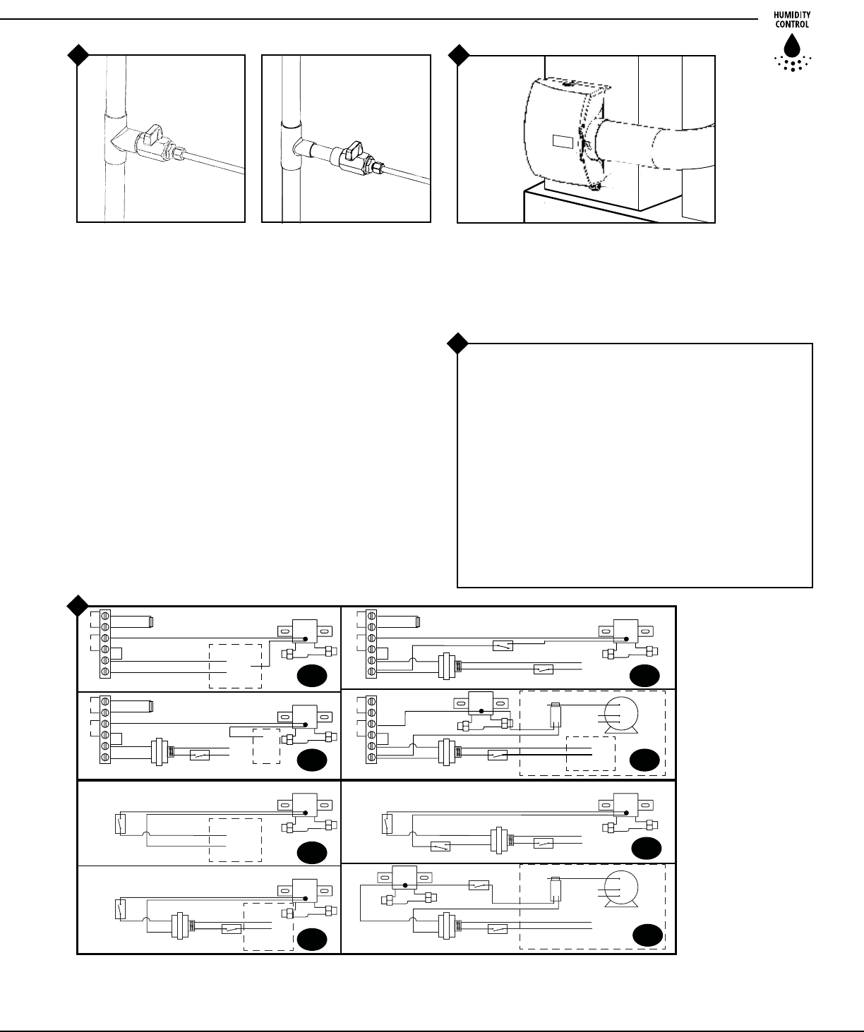
Connect by-pass pipe to collar and humidier cabinet.
Using holes at top and boom of side panel discharge,
pierce 2 self tapping screws through by-pass pipe.
COPPER
TUBING
Hot Water
PLASTIC
TUBING
Cold Water
Compression
Nut
Sleeve
Insert
Saddle Valve Installaon Opon: Mount the self tapping
saddle valve (4a) or code valve (4b next page) on either a
cold or hot water* pipe. A side or top mount is best to avoid
clogging from pipe sediment. Connect 1/4˝ O.D. tubing to
the saddle valve. Copper tubing requires a brass compression
nut and brass sleeve. Plasc tubing requires a brass compres-
sion nut, a brass insert inside the tubing and a plasc sleeve
on the outside.
NOTE: DO NOT USE PLASTIC TUBING ON HOT WATER OR IN CON-
TACT WITH ANY HOT PLENUM SURFACE OR DUCT. INSTALLATION
OF THIS SADDLE VALVE MUST MEET OR EXCEED LOCAL CODES AND
ORDINANCES. USING HOT WATER WILL INCREASE THE AMOUNT OF
HUMIDITY DELIVERED TO THE HOME, AND WILL ALSO INCREASE
THE DEMAND ON THE HOME’S DOMESTIC HOT WATER SYSTEM.
1 3
Attach by-pass pipe
to humidier here
1
2
WIRE JUMPER
(HOT)
115v.
60CY.
ON-OFF SWITCH
COMMON LEAD
FURNACE
C
HI
LO
GA50
CURRENT
SENSING
RELAY
MULTI
SPEED
BLOWER
MOTOR
AC L
AC N
HUM
24V. SOLENOID VALVE
727-58 24 V. TRANSFORMER
(HOT)
C
115v.
60CY.
ON-OFF SWITCH
AC L
AC N
HUM
SNSR
24V. SOLENOID VALVE
24 V. TRANSFORMER
L1
C
NO
(HOT)
L2
115v.
60CY.
ON-OFF SWITCH
HEP-12500 AIR
PRESSURE SWITCH
AC L
AC N
HUM
SNSRSNSR
SNSR
24V. SOLENOID VALVE
24 V. TRANSFORMER
R
FURNACE
CONTROL BOARD
C
24v.
60CY.
AC L
AC N
HUM
24V. SOLENOID VALVE
FURNACE
BOARD
W
WIRE JUMPER
OUTDOOR TEMP. SENSOR
OUTDOOR TEMP. SENSOR
OUTDOOR TEMP. SENSOR
OUTDOOR TEMP. SENSOR
N
W
24v.
60CY.
ACC
EAC
(HOT)
C
115v.
60CY.
ON-OFF SWITCH
COMMON LEAD
FURNACE
C
HI
LO
GA50
CURRENT
SENSING
RELAY
MULTI
SPEED
BLOWER
MOTOR
24V. SOLENOID VALVE
HUMIDISTAT
24 V. TRANSFORMER
(HOT)
C
115v.
60CY.
ON-OFF SWITCH
24V. SOLENOID VALVE
24V. SOLENOID VALVE
24 V. TRANSFORMER
L1
C
NO
(HOT)
L2
115v.
60CY.
ON-OFF SWITCH
HEP-12500 AIR
PRESSURE SWITCH
24 V. TRANSFORMER
HUM
FURNACE
CONTROL BOARD
C
24v.
60CY.
24V. SOLENOID VALVE
HUMIDISTAT
HUMIDISTAT
HUMIDISTAT
FURNACE
BOARD
WIRE
JUMPER
WIRE
JUMPER
WIRE
JUMPER
WWW.CLEANCOMFORT.COM
3
IO-HE12-A IO-HE12-A
3/4˝ TEE
1/2˝ TEE
HEP-GCV3412 Code Valve Installation Option:
Copper Pipe
1. Turn o water supply.
2. Clean pipe, ngs and valve with sandpaper or wire brush.
3. Apply a thin layer of ux to all surfaces to be soldered.
4. Assemble valve to pipe and/or ngs.
5. Cooling the valve by wrapping a weed rag around
the valve is oponal.
6. Heat the joints with a torch. Apply solder to each joint.
Connue to apply heat sucient to keep solder liquid.
7. Aer solder has lled enre joint area, remove heat
and allow joint to cool. Do not move or disturb.
8. Slide compression nut over 1/4˝ copper tube
followed by compression sleeve.
9. Insert tube into valve fully and ghten nut.
10. Turn on water supply and check for leaks.
4b
5
6
7A-7D Electronic
Humidistat
7A – To furnace control board
24 volts
7B – To constant power using
24V transformer and
pressure switch
7C – To furnace control board
115 volts with 24V
transformer
7D – To constant power using
24V relay and current
sensing relay
7E-7H Manual Humidistat
7E – To furnace control board
24 volts
7F – To constant power using
24V transformer and
pressure switch
7G – To furnace control board
115 volts with 24V
transformer
7H – To constant power using
24V relay and current
sensing relay
Connect 1/4˝supply tube at inlet of solenoid (there is an internal
brass lter beyond inlet, not shown). DO NOT USE PLASTIC
TUBING IN CONTACT WITH ANY HOT PLENUM
SURFACE OR DUCT. IF USING PLASTIC TUBING,
USE TUBE SUPPORT HEP-P189 AND PLASTIC COM-
PRESSION SLEEVE HEP-P190 (Supplied with humidier).
Connect drain hose to 1/2˝ spout on humidier cabinet using
hose clamp. Run 1/2˝ hose to suitable drain such as oor drain,
sewer or laundry sink. Be sure hose has connuous slope and is
not kinked at any point.
Turn damper knob to winter (open) posion. Turn on water
supply and check operaon of humidier. Set humidistat to a
demand seng. With the furnace o, the solenoid valve should
be closed. Start the furnace, the solenoid valve should open
when the blower or burner circuit is energized. Check ow
of water through distributor trough and evaporator pad.
The standard HEP-GA4231 YELLOW orice will supply
approximately 3.5 GPH of water at a line water pressure
of 60 psi. For low water pressures (20-40 psi) a larger ORANGE
orice HEP-GA4299 is available to provide the same ow.
Leave humidistat set at the recommended seng.
7
7A
7E
7G
7H
7D
7F
7B
7C
* CODE VALVE IS INCLUDED WITH AUTOMATIC MODELS ONLY,
but can be purchased separately as part number HEP-GCV3412.

HEP-
P102 COMPRESSION SLEEVE
HEP-
P101 COMPRESSION NUT
HEP-570-40 PAD RAIL
HEP-570-1 CHASSIS
HEP-GA4226 DISTRIBUTOR TUBE
HEP-GA4040 SOLENOID
VALVE ASSEMBLY
HEP-GA4004 STAINER SCREEN
HEP-P189 BRASS TUBE INSERT
HEP-P101 COOMPRESSION UNIT
HEP-P190 COMP. SLEEVE (PLASTIC) /P102
COMP. SLEEVE (BRASS)
HEP-GA4231 YELLOW ORIFICE
HEP-900-14 DRAIN PAN
HEP-900-71 BADGE
HEP-570-13 COVER
HEP-900-11 DAMPER KNOB
HEP-900-28 DAMPER DISK
HEP-570-2 SIDE PANEL
DISCHARGE
HEP-900-9 NOZZLE
HEP-GA-10 EVAPORATOR PAD
HEP-900-15 DISTRIBUTOR TROUGH
HEP-900-10 SPOUT
PARTS LIST FOR HUMIDIFIER
4
WWW.CLEANCOMFORT.COM
IO-HE12-A IO-HE12-A
CARE AND MAINTENANCE
Your humidier is engineered to give helpful and
trouble-free humidication. For maximum eciency
the following cleaning procedures should be carried
out at the end of each heating season:
1. Turn o water supply and turn humidistat seng to the
“OFF” posion.
2. Remove humidier's front cover, distributor trough,
evaporator pad and drain pan. Clean excessive mineral
deposits from the distributor trough, drain pan, pad rails,
and humidier cover and chassis. A soluon of 1/2 vinegar
& 1/2 water will help loosen mineral deposits, or you may
use a common household de-scaler.
3. Replace evaporator pad part number HEP-GA19 seasonally.
(Some instances require 2 pad replacements per heang
season, depending on water hardness.) Install trough and
drain pan. Replace cover. For peak performance do not
aempt to clean evaporator pads, or use longer than one
heang season.
4. In areas where the supply water for the humidier contains
a high mineral content, OR if the solenoid valve fails to
operate, the solenoid and the strainer screen should be in-
spected and descaled. To do this disconnect the 1/4˝ water
supply line from the solenoid valve. Carefully pull the
strainer screen (part number HEP-GA19 ) from the valve
HE12MB Models shipped to
Canada, also contain (Not shown
on diagram):
• HEP-1042-28 Bypass Kit (Includes
ex duct, start collar and 15�
drain hose)
• HEP-747-38 Water Supply
Tubing Kit (Includes water
hose, Compression Nuts,
2 Compression Sleeves
and 2 Brass Tube Inserts)
• HEP-1042-40 Extra Die Cut
• HEP-1040-13 Ring Flange
• HEP-990-31 15� Drain Tube
• HEP-570-80 Hardware
• MHX3 Wall Mount
Humidistat (allows mounng
on wall or in duct)
Humidistats (Not Shown):
HE12 “A” Models = HEP-GFX3
HE12 “M” Models = HEP-MHX3
At Outside
Temperature
Recommended
Setting
-20 ° F -29 ° C 15%
-10 ° F -23 ° C 20%
0 ° F -18 ° C 25%
+10 ° F -12° C 30%
+20 ° F -7 ° C 35%
+30 ° F -1 ° C 40%
body (part number HEP-900-6). Clean the mineral deposits
from all parts. If the orice is clogged, it may be opened by
inserng a small pin. Reassemble the brass ngs, ensuring
the strainer screen has been fully seated.
5. Reconnect the 1/4˝ water line to the solenoid valve if
necessary. Turn on the water supply and check all points for
leakage. The operaon of the unit may
be checked by starng the furnace. The humidier operates
only when the furnace blower is running or the burner circuit
is energized. The humidier is now ready for operaon.
6. During the summer, turn o water supply and turn the
humidistat seng to the “OFF” posion. Close air damper
disk on the humidier.

HOW THE HUMIDIFIER WORKS
5
WWW.CLEANCOMFORT.COM
IO-HE12-A IO-HE12-A
TROUBLESHOOTING (By Licensed Professionals Only)
The operang principle of the humidier is based on the
most ecient and economical means of evaporang water
to the air. The humidier uses only 2.5 was of electrical
power during operaon, less than the smallest household
light bulb. The heat necessary for evaporang water is
produced by the furnace.
The water supply to the humidier is controlled by the
electric solenoid valve. The humidistat connected in series
with the solenoid provides low voltage control of the
humidier. The humidistat is designed for wall mounng in
the living area or surface mounng on the return air duct.
ELECTRICAL RATING: 24 VAC / 60 Hz.
Water ows through a strainer, is metered through an
orice to provide the proper amount of water, and is supplied
to the evaporator pad by the distributor trough. Approxi-
mately 200 CFM of air is by-passed from the warm air
plenum through the humidier and returned to the cold
air plenum. Moisture is evaporated to the air passing
through the evaporator pad.
Minerals are not blown into the air stream, but are le on
the evaporator pad where a high percentage is carried o
with the waste water. When the humidier is installed and
operang, no adjustments are necessary other than seng
the control knob on the humidistat to the desired level of
humidicaon. Set the damper knob on the humidier to
“WINTER” posion. To turn the humidier o, close water
supply valve and turn humidistat to the “OFF” posion.
If furnace is used for summer cooling or venlang set the
damper knob to “SUMMER”.
DO NOT SET RELATIVE HUMIDITY TOO HIGH DURING
COLD WEATHER. EXCESSIVE HUMIDITY MAY CAUSE
CONDENSATION ON WINDOWS OR IN WALLS. REFER
TO RECOMMENDED SETTINGS AS DESCRIBED IN THE
HUMIDISTAT OWNERS MANUAL.
1. Verify water supply is on.
2. Verify metering orice is not obstructed. Very hard water with high mineral content may restrict
the metering orice in as lile as one heang season. Replace metering orice if restricted.
(part number HEP-GA4231).
1. Replacement parts can be purchased through the installing contractor.
1. Verify humidier and humidistat wiring. Humidier should operate with furnace burner
or blower cycle.
1. Reduce the seng on the humidistat*. Refer to CARE AND MAINTENANCE secon of this manual
to esmate a humidity seng for the home based on outside temperature.
Proper voltage present at
solenoid valve (24 VAC
but no water ow.
Humidier runs without
furnace operaon or
humidier never shuts o.
Too much humidity in home
and/or condensaon on
windows.
Where can I purchase
replacement parts?
TECHNICAL SUPPORT • 1-855-303-1821 • www.cleancomfort.com
Symptoms
Humidier will not operate.
Diagnostic Steps
1. Verify that the operang mode of the home’s thermostat is set to “HEAT”. Adjust the setpoint
on the thermostat to 5 degrees higher than the current room temperature. This should force
the furnace on (you may need to wait up to 2 minutes before the furnace’s blower motor starts).
Operaon of the furnace may be necessary to power the humidier.
2. Humidity level in home may be higher than humidistat seng. Increase humidity seng on
humidistat.*
3. Verify water supply is on.
4. Check for voltage at the solenoid valve. Voltage should be 24VAC. Bypass the humidistat if
necessary to isolate the solenoid valve circuit.
5. Verify wiring of humidier and humidistat.
* The humidistat is generally located on furnace return plenum, or on an inside wall in the living space.

HUMIDIFIER SPECIFICATIONS
6
WWW.CLEANCOMFORT.COM
IO-HE12-A IO-HE12-A
Approximate size of home that can be humidied by each humidier model, based on air ghtness of the home.
Humidier Chassis with plenum
cut out shown as dashed lines
Model GPD
Loose
(0.75 AC/H)
Average
(0.50 AC/H)
Tight
(0.30 AC/H)
HE12 12 800 sq. . 1200 sq. . 2000 sq. .
HE17 17 1115 sq. . 1650 sq. . 2800 sq. .
HE18 18 1175 sq. . 1770 sq. . 3000 sq. .
Humidier Performance Baseline Criteria
Outside Design Temp 0° F / -18° C
Outside Design R.H. 70% R.H.
Inside Design Temp. 70° F / 21° C
Inside Design R.H 30% R.H.
15-1/2˝
13-3/4˝
13-1/4˝
8-7/8˝
9-1/2˝
Footnote: If plenum temperature is less than 120° F / 49° C, the amount of humidity delivered to the home will be less than
the GPD specicaon shown above.
HUMIDIFIER PACKAGED COMPONENT ACCESSORIES
Model HE12A includes:
Humidier components: HEP-GA10 Vapor pad, HEP-GA4040 solenoid assembly, Integral Bypass Damper
Accessories: HEP-GFX3 Automac Digital Humidistat, 24V Transformer, Code Valve, Saddle Valve
Model HE12M includes:
Humidier Components: HEP-GA10 Vapor Pad, HEP-GA4040 Solenoid Assembly, Integral Bypass Damper
Accessories: HEP-MHX3 Manual Humidistat, 24V Transformer, Saddle Valve
Air Changes/Hour (AC/H) 0.30
Ceiling Height 8 ft
Furnace Plenum Temp. 120° F / 49° C
Furnace run time for
calculating sq. ft. 8hr/1 day

WARRANTY REGISTRATION
7
WWW.CLEANCOMFORT.COM
IO-HE12-A IO-HE12-A
LIMITED WARRANTY
What This Limited Warranty Covers
Daikin North America LLC (“Daikin”) warrants that, for the period
stated below, its HE Series evaporave humidier (the “Product”)
will be free from defects in manufacturing or materials.
What This Limited Warranty Does Not Cover
This limited warranty does not cover components or materials used
in the installaon of the Product, including, but not limited to, wiring,
fasteners, ductwork, gaskets, pipes, or tubes. This warranty does not
cover evaporator pads, water strainers, or metering orices.
Who Has Rights under this Limited Warranty
This limited warranty runs to the original purchaser of the Product(s)
who owns, and resides in, the residenal dwelling in which the
Product(s) are inially installed (“you”).
Other Limitations
Remedies under this limited warranty are condioned upon the
normal use and care of the Product(s). The Product must have been
installed according to its manual and all applicable wiring diagrams,
in addion to all applicable building and construcon codes and all
other applicable law. This limited warranty does not cover damage
caused by misuse, neglect, re, damage in transit, sediment, poor
water quality, or other casualty, damage caused during installaon,
or any cause beyond the control of Daikin. This warranty does not
cover Products placed into commercial or industrial service.
How Long This Limited Warranty Lasts
This limited warranty begins on the date upon which the Product is
installed. The limited warranty lasts for 10 years.
Registering Your Product
To be eligible for warranty coverage, you must register your Product
within 30 days aer installaon. You can register your Product in any
of the following ways.
• Return the Product registraon card within 30 days aer
the Product is installed.
• If you have any diculty with this method, you can call Daikin
at 1-855-303-1821 for assistance.
Failure by California or Quebec residents to register the
Product does not diminish their warranty rights.
How to Obtain Service
• Contact the contractor from whom you purchased the
Products(s), or
• Contact Daikin using the informaon below.
What Daikin Will Do
If the Product(s) covered by this limited warranty are not as
warranted and you nofy Daikin of such failure during the term of
the limited warranty, Daikin will, at its opon, furnish replacement
part(s) and/or whole replacement Product(s). If the exact original
Product or part is no longer available, Daikin reserves the right to
substute a similar part or Product of equal or greater quality. All
replacement parts or Products will be shipped either to the original
selling contractor or directly to you. You must pay for all shipping of
replacement part(s) and/or Product(s). Labor, de-installaon costs,
and re-installaon costs are not covered by this limited warranty.
Daikin reserves the right to inspect any Product(s) that you believe
fails to meet the requirements of this limited warranty and you must
allow Daikin or its representaves all access reasonably necessary to
perform such inspecons or at Daikin’s request, return the Product(s).
Any part replaced pursuant to this warranty is warranted only for the
unexpired poron of the warranty term applying to the original part.
Limitation of Liability
IN NO EVENT WILL DAIKIN BE LIABLE FOR ANY INCIDENTAL OR
CONSEQUENTIAL DAMAGES ARISING OUT OF THE FAILURE OF THE
PRODUCT, WHETHER BASED ON BREACH OF EXPRESS OR IMPLIED
WARRANTY, OTHER BREACH OF CONTRACT, NEGLIGENCE OR
OTHER TORT. Some states and provinces do not allow the exclusion
or limitaon of incidental or consequenal damages, so the above
limitaon may not apply to you.
Your Rights Under State Law
This warranty gives you specic legal rights, and you may also have
other rights which vary from state to state or province to province.
How to Contact Daikin
You may contact Daikin about warranty quesons or claims using
the following contact informaon: by mail at 43800 Grand River,
Novi, Michigan, 48375 or, by telephone at 1-855-303-1821.

HUMIDIFIER
WWW.CLEANCOMFORT.COM
IO-HE12-A 10/13
Our connuing commitment to quality products may mean a change in specicaons without noce.
©2013 DAIKIN NORTH AMERICA LLC.
Houston, Texas • USA
TECHNICAL SUPPORT • 1-855-303-1821
Register by mailing the form below
Mail Form To:
Clean Comfort
An: Warranty Dept.
43800 Grand River Ave.
Novi, MI 48375
Product Information:
Serial Number: ________________________________________________________________________
Model: ______________________________________________________________________________
Install Date: Month ______________________ Day ___________ Year _________________________
Owner Information:
Contractor Name: _____________________________________________________________________
Address: _____________________________________________________________________________
Address 2: ____________________________________________________________________________
City: ______________________________ State: _________________ Zip Code: __________________
Phone: _______________________________________________________________________________
Email: _______________________________________________________________________________
Contractor Information:
Contractor Name: _____________________________________________________________________
Address: ___________________________________________________________________________
Address 2: ___________________________________________________________________________
City: ______________________________ State: _________________ Zip Code: __________________
Contractor Phone: _____________________________________________________________________
Contractor Email: ______________________________________________________________________
Cut Along Dashed Line
