
Futurecom Systems Group, ULC
VR Programming Guide
Document: 8G093X01
Revision :R6.2
Date: August 2023

8G093X01 R6.2
VR Programming Guide
August 2023 Page 2 of 146
NOTES

8G093X01 R6.2
VR Programming Guide
August 2023 Page 3 of 146
Contents
Contents .......................................................................................................................... 3
Manual Revisions ............................................................................................................ 7
Foreword .......................................................................................................................... 8
Computer Software Copyrights ..................................................................................... 9
Publicly Available Software List .................................................................................. 10
Publicly Available Software – Common Licenses ....................................................... 11
CodeGuru License ...................................................................................................... 14
Document Copyrights ................................................................................................. 14
Disclaimer ................................................................................................................... 14
Trademarks ................................................................................................................. 14
Commercial Warranty ................................................................................................. 14
Declaration of Conformity............................................................................................ 15
Important Safety Information ....................................................................................... 15
Notice to Users (FCC/ISED) ....................................................................................... 15
Déclaration de Conformité .......................................................................................... 16
Informations de Sécurité Importantes ......................................................................... 16
Avis Aux Utilisateurs (FCC / ISED) ............................................................................. 16
VR Programming Basics .............................................................................................. 17
Key Terminology ......................................................................................................... 17
Installing Futurecom Repeater Configurator (FRC) .................................................... 17
Previous Installation .............................................................................................................. 17
New Installation ..................................................................................................................... 17
Menu Bar .................................................................................................................... 18
Help Menu ............................................................................................................................. 19
Compatibility Charts .............................................................................................................. 19
Using FRC on-line ....................................................................................................... 20
Setting Up Communications with the VR .................................................................... 20
Reading from the VR (Uploading Data) ...................................................................... 20
Writing to the VR (Downloading Data) ........................................................................ 20
Understanding FRC Programming Files ..................................................................... 20
Codeplug Applications ........................................................................................................... 21
Data Categories ..................................................................................................................... 21

8G093X01 R6.2
VR Programming Guide
August 2023 Page 4 of 146
Codeplug Content.................................................................................................................. 21
Codeplug Encryption ............................................................................................................. 21
Codeplug Summary ............................................................................................................... 22
FRC Icons ................................................................................................................... 22
How To Create an EPR File ........................................................................................ 23
How To Create a DPD File.......................................................................................... 24
Creation of New File .............................................................................................................. 24
Modify an Existing File .......................................................................................................... 25
How To Create a DCD File ......................................................................................... 27
Creation of New File .............................................................................................................. 27
Modify an Existing File .......................................................................................................... 28
Feature Licenses ........................................................................................................ 30
Introduction ............................................................................................................................ 30
License Delivery .................................................................................................................... 30
Applying License to Repeater via FRC ................................................................................. 30
Bundling a License File with a DCD File ............................................................................... 33
Applying License to Template Files ....................................................................................... 34
How To Clone a VR .................................................................................................... 35
Steps for Cloning ................................................................................................................... 35
Using FRC Off-Line ..................................................................................................... 37
Viewing Codeplugs Off-Line .................................................................................................. 37
Modifying Codeplugs Off-Line ............................................................................................... 37
Saving Codeplugs Off-Line ................................................................................................... 37
Applying Firmware to VR ............................................................................................ 38
Upgrading Firmware ................................................................................................... 41
Downgrading Firmware ............................................................................................... 42
VR Programming Guidelines ....................................................................................... 43
Programming Steps Overview .................................................................................... 43
Additional CPS Programming for VR .......................................................................... 43
VR Basic Programming ............................................................................................... 44
VR Feature Programming ........................................................................................... 45
VR Fine Tuning ........................................................................................................... 47
P25 Trunking OTAR via VR ........................................................................................ 47
MSU Scan Programming Requirements ..................................................................... 47
MSU Group Services Programming Requirements .............................................................. 47
Exporting MSU data (.xml file) ............................................................................................... 48
Programming the PSUs for DVRS Operation ............................................................. 48
Programming the P25 ‘DVRS Enabled’ PSU .............................................................. 48
XTS Series ‘DVRS Enabled’ PSUs ............................................................................. 48
APX Series ‘DVRS Enabled’ PSUs ............................................................................. 49
Programming of Generic P25 PSU for Digital VR Mode ............................................. 49

8G093X01 R6.2
VR Programming Guide
August 2023 Page 5 of 146
Programming of the P25 PSU (Generic P25 or ‘DVRS Enabled’) for operation on
Conventional P25 MSU System .................................................................................. 49
Programming of the P25 XTS PSU (Generic P25 or ‘DVRS Enabled’) for Inbound Digital
Takeover ..................................................................................................................... 50
Programming of Analog Conventional PSU for Analog VR Mode ............................... 50
Feature Programming ................................................................................................. 51
How to Program GPS Driven Deactivation Feature .............................................................. 51
How to Program NAC Linking Feature .................................................................................. 54
How to Program TPS Signaling ............................................................................................. 55
How to Program Talkgroup Matching .................................................................................... 56
How to Program Talkgroup Proxying .................................................................................... 57
How to Program Talkgroup Translation ................................................................................ 59
How to Program Unit ID Translation ...................................................................................... 62
How to Program Emergency Revert ...................................................................................... 63
Documentation Conventions ....................................................................................... 66
Options ........................................................................................................................ 68
Ports ............................................................................................................................ 68
Repeater Setup ........................................................................................................... 69
RF / Analog Setup ................................................................................................................. 69
Frequency Band Setup .......................................................................................................... 69
Repeater Info ........................................................................................................................ 70
Hardware / Software Info ....................................................................................................... 72
Update Info ............................................................................................................................ 72
Personality Data .......................................................................................................... 74
Repeater Channel Setup Window ......................................................................................... 74
Mode Change ........................................................................................................................ 80
Mode Change of VR by Local PSU ...................................................................................... 80
Remote Mode change of VR by Dispatcher / System PSU .................................................. 81
Mobile Radio Channel Setup ................................................................................................. 82
Hardware Setup Window ............................................................................................ 90
MSU Data .............................................................................................................................. 95
PSU IDs Allowed ................................................................................................................... 95
VR Remote Activation IDs ..................................................................................................... 95
PSU NAC Table ..................................................................................................................... 95
Analog Setup .............................................................................................................. 96
VR Common Setup ................................................................................................... 101
MSU Interface Setup ................................................................................................. 107
Emergency Setup ..................................................................................................... 109
Tone Setup ............................................................................................................... 112
Station ID Setup ........................................................................................................ 112
Digital Setup .............................................................................................................. 113
Primary / Secondary Setup ....................................................................................... 119
Maintenance Screens ................................................................................................. 122

8G093X01 R6.2
VR Programming Guide
August 2023 Page 6 of 146
Using the Monitoring Screen ..................................................................................... 122
RSSI Setup ............................................................................................................... 125
Troubleshooting .......................................................................................................... 132
Appendix 1 – VR Status Display ................................................................................ 136
Appendix 2 – Grant Timeout Timer ........................................................................... 137
Appendix 3 – Icon Legend ......................................................................................... 138
Appendix 4 – CPS VR Related Programming ........................................................... 139
Glossary ....................................................................................................................... 142
Reference ..................................................................................................................... 145
Contact Information .................................................................................................... 146

8G093X01 R6.2
VR Programming Guide
August 2023 Page 7 of 146
Manual Revisions
Rev #
Date
Notes & References
0
October 2020
Original Release
1
February 2021
Update for SR2021.1
2
July 2021
Update for SR2021.2
3
August 2021
Update for SR2021.3
4
November 2021
Update for SR2021.4
5
August 2022
Update for SR2022.2
5.01
October 2022
CPS – MSU/PSU Programming for TPS Signaling
6
December 2022
Update for SR2022.3
6.1
March 2023
Update for SR2023.1
6.2
August 2023
Update for SR2023.2

8G093X01 R6.2
VR Programming Guide
August 2023 Page 8 of 146
Foreword
Futurecom Vehicular Repeater (VR) is designed to be seamlessly interfaced to:
Remote Mount APX Series Mobile Subscriber Unit (MSU) with or without control head
When the VR is interfaced to a Remote Mount Motorola APX Mobile Radio, the complete
equipment package is referred to as Digital Vehicular Repeater System (DVRS).
For compatibility requirements for Mobile and Portable radios refer to Futurecom website →
Support → Documentation and Software → DVR-LX → Firmware → Compatibility Charts
For details on the APX series Mobile or Portable Radios operation, please refer to the applicable
Manuals available from Motorola.
For details on how to operate a VR, please refer to the Vehicular Repeater (VR) User’s Guide
Template available on Futurecom website → Support → Documentation and Software → DVR-
LX → User Guide
Futurecom Repeater Configurator (FRC) contains three main components to service all
hardware programming needs:
1. Configurator for APX Repeaters (VRX1000, DVR and DVR-LX
®
)
2. Configurator for PDR8000
®
3. Flash Downloader Utility
This is used to update the firmware of the repeater. In the past the user had to download
it separately from the Futurecom website, integrating into FRC makes it more of an all-
in-one utility and adds a layer of convenience.
FRC is backwards compatible with all VR firmware versions. It supports reading all previously
configured devices. It is continually updated with business rules to ensure integrity of VR
configuration.

8G093X01 R6.2
VR Programming Guide
August 2023 Page 9 of 146
Computer Software Copyrights
The products described in this manual include copyrighted Futurecom computer programs stored
in semiconductor memories or other media. Laws in the United States, Canada and other
countries preserve for Futurecom certain exclusive rights for copyrighted computer programs,
including but not limited to, the exclusive right to copy or reproduce in any form the copyrighted
computer programs. Any copyrighted computer program contained in the Futurecom products
described in this manual may not be copied, reproduced, modified, reverse-engineered, or
distributed in any manner without the express written permission of Futurecom. The purchase of
Futurecom products shall not be deemed to grant either directly or by implication, estoppels, or
otherwise, any license under the copyrights, patents, or patent applications of Futurecom, except
for the normal non-exclusive license to use that arises by operation of law in the sale of a product.

8G093X01 R6.2
VR Programming Guide
August 2023 Page 10 of 146
The Futurecom Repeater Configurator provided by Futurecom Systems Group ULC includes the
following Publicly Available Software.
Publicly Available Software List
Name: MFC Grid Control
Version: 2.24
Modified: Yes
Software Site: http://www.codeproject.com/KB/miscctrl/gridctrl.aspx
Source Code: No Source Code Distribution Obligations. The Source Code may be obtained from the original Software
Site.
License: The Article associated with the Source Code is licensed under the Code Project Open License (CPOL),
version 1.02. Reference the Common Licenses Section for the terms of the CPOL. The Source Code licensed is under
Custom Freeware / Open Source Software License, see below:
Written by Chris Maunder <chris@codeproject.com
>
Copyright (c) 1998-2002. All Rights Reserved.
This code may be used in compiled form in any way you desire. This file may be redistributed unmodified by any means
PROVIDING it is not sold for profit without the authors written consent, and providing that this notice and the authors
name and all copyright notices remains intact.
An email letting me know how you are using it would be nice as well.
This file is provided "as is" with no expressed or implied warranty.
The author accepts no liability for any damage / loss of business that this product may cause.
Additional Notices:
CInPlaceEdit, http://www.codeguru.com/listview/edit_subitems.shtml
, licensed under the CodeGuru License.
Refer to the Common Licenses Section for the terms of the CodeGuru License.
Credits:
Zafir Anjum
Eric Woodruff
Ken Bertelson
Joe Willcoxson

8G093X01 R6.2
VR Programming Guide
August 2023 Page 11 of 146
Publicly Available Software – Common Licenses
The Code Project Open License (CPOL) 1.02
Preamble
This License governs Your use of the Work. This License is intended to allow developers to use the Source Code and
Executable Files provided as part of the Work in any application in any form.
The main points subject to the terms of the License are:
• Source Code and Executable Files can be used in commercial applications.
• Source Code and Executable Files can be redistributed; and
• Source Code can be modified to create derivative works.
• No claim of suitability, guarantee, or any warranty whatsoever is provided. The software is provided "as-is".
• The Article accompanying the Work may not be distributed or republished without the Author's consent.
This License is entered between You, the individual or other entity reading or otherwise making use of the Work licensed
pursuant to this License and the individual or other entity which offers the Work under the terms of this License
("Author").
License
THE WORK (AS DEFINED BELOW) IS PROVIDED UNDER THE TERMS OF THIS CODE PROJECT OPEN LICENSE
("LICENSE"). THE WORK IS PROTECTED BY COPYRIGHT AND/OR OTHER APPLICABLE LAW. ANY USE OF THE
WORK OTHER THAN AS AUTHORIZED UNDER THIS LICENSE OR COPYRIGHT LAW IS PROHIBITED.
BY EXERCISING ANY RIGHTS TO THE WORK PROVIDED HEREIN, YOU ACCEPT AND AGREE TO BE BOUND
BY THE TERMS OF THIS LICENSE. THE AUTHOR GRANTS YOU THE RIGHTS CONTAINED HEREIN IN
CONSIDERATION OF YOUR ACCEPTANCE OF SUCH TERMS AND CONDITIONS. IF YOU DO NOT AGREE TO
ACCEPT AND BE BOUND BY THE TERMS OF THIS LICENSE, YOU CANNOT MAKE ANY USE OF THE WORK.
1. Definitions.
a. "Articles" means, collectively, all articles written by Author which describes how the Source Code and
Executable Files for the Work may be used by a user.
b. "Author" means the individual or entity that offers the Work under the terms of this License.
c. "Derivative Work" means a work based upon the Work or upon the Work and other pre-existing
works.
d. "Executable Files" refer to the executable files, binary files, configuration, and any required data files
included in the Work.
e. "Publisher" means the provider of the website, magazine, CD-ROM, DVD or other medium from or
by which the Work is obtained by You.
f. "Source Code" refers to the collection of source code and configuration files used to create the
Executable Files.
g. "Standard Version" refers to such a Work if it has not been modified or has been modified in
accordance with the consent of the Author, such consent being in the full discretion of the Author.
h. "Work" refers to the collection of files distributed by the Publisher, including the Source Code,
Executable Files, binaries, data files, documentation, whitepapers and the Articles.
i. "You" is you, an individual or entity wishing to use the Work and exercise your rights under this
License.
2. Fair Use / Fair Use Rights. Nothing in this License is intended to reduce, limit, or restrict any rights arising
from fair use, fair dealing, first sale or other limitations on the exclusive rights of the copyright owner under
copyright law or other applicable laws.
3. License Grant. Subject to the terms and conditions of this License, the Author hereby grants You a worldwide,
royalty-free, non-exclusive, perpetual (for the duration of the applicable copyright) license to exercise the rights
in the Work as stated below:
a. You may use the standard version of the Source Code or Executable Files in Your own applications.

8G093X01 R6.2
VR Programming Guide
August 2023 Page 12 of 146
b. You may apply bug fixes, portability fixes and other modifications obtained from the Public Domain
or from the Author. A Work modified in such a way shall still be considered the standard version and
will be subject to this License.
c. You may otherwise modify Your copy of this Work (excluding the Articles) in any way to create a
Derivative Work, if you insert a prominent notice in each changed file stating how, when and where
You changed that file.
d. You may distribute the standard version of the Executable Files and Source Code or Derivative Work
in aggregate with other (possibly commercial) programs as part of a larger (possibly commercial)
software distribution.
e. The Articles discussing the Work published in any form by the author may not be distributed or
republished without the Author's consent. The author retains copyright to any such Articles. You may
use the Executable Files and Source Code pursuant to this License, but you may not repost or
republish or otherwise distribute or make available the Articles, without the prior written consent of
the Author.
Any subroutines or modules supplied by You and linked into the Source Code or Executable Files of this Work
shall not be considered part of this Work and will not be subject to the terms of this License.
4. Patent License. Subject to the terms and conditions of this License, each Author hereby grants to You a
perpetual, worldwide, non-exclusive, no-charge, royalty-free, irrevocable (except as stated in this section)
patent license to make, have made, use, import, and otherwise transfer the Work.
5. Restrictions. The license granted in Section 3 above is expressly made subject to and limited by the following
restrictions:
a. You agree not to remove any of the original copyright, patent, trademark, and attribution notices and
associated disclaimers that may appear in the Source Code or Executable Files.
b. You agree not to advertise or in any way imply that this Work is a product of Your own.
c. The name of the Author may not be used to endorse or promote products derived from the Work
without the prior written consent of the Author.
d. You agree not to sell, lease, or rent any part of the Work. This does not restrict you from including
the Work or any part of the Work inside a larger software distribution that itself is being sold. The
Work by itself, though, cannot be sold, leased or rented.
e. You may distribute the Executable Files and Source Code only under the terms of this License, and
You must include a copy of, or the Uniform Resource Identifier for, this License with every copy of
the Executable Files or Source Code You distribute and ensure that anyone receiving such
Executable Files and Source Code agrees that the terms of this License apply to such Executable
Files and/or Source Code. You may not offer or impose any terms on the Work that alter or restrict
the terms of this License or the recipients' exercise of the rights granted hereunder. You may not
sublicense the Work. You must keep intact all notices that refer to this License and to the disclaimer
of warranties. You may not distribute the Executable Files or Source Code with any technological
measures that control access or use of the Work in a manner inconsistent with the terms of this
License.
f. You agree not to use the Work for illegal, immoral or improper purposes, or on pages containing
illegal, immoral or improper material. The Work is subject to applicable export laws. You agree to
comply with all such laws and regulations that may apply to the Work after Your receipt of the Work.
6. Representations, Warranties and Disclaimer. THIS WORK IS PROVIDED "AS IS", "WHERE IS" AND "AS
AVAILABLE", WITHOUT ANY EXPRESS OR IMPLIED WARRANTIES OR CONDITIONS OR
GUARANTEES. YOU, THE USER, ASSUME ALL RISK IN ITS USE, INCLUDING COPYRIGHT
INFRINGEMENT, PATENT INFRINGEMENT, SUITABILITY, ETC. AUTHOR EXPRESSLY DISCLAIMS ALL
EXPRESS, IMPLIED OR STATUTORY WARRANTIES OR CONDITIONS, INCLUDING WITHOUT
LIMITATION, WARRANTIES OR CONDITIONS OF MERCHANTABILITY, MERCHANTABLE QUALITY OR
FITNESS FOR A PARTICULAR PURPOSE, OR ANY WARRANTY OF TITLE OR NON-INFRINGEMENT,
OR THAT THE WORK (OR ANY PORTION THEREOF) IS CORRECT, USEFUL, BUG-FREE OR FREE OF
VIRUSES. YOU MUST PASS THIS DISCLAIMER ON WHENEVER YOU DISTRIBUTE THE WORK OR
DERIVATIVE WORKS.
7. Indemnity. You agree to defend, indemnify and hold harmless the Author and the Publisher from and against
any claims, suits, losses, damages, liabilities, costs, and expenses (including reasonable legal or attorneys’
fees) resulting from or relating to any use of the Work by You.
8. Limitation on Liability. EXCEPT TO THE EXTENT REQUIRED BY APPLICABLE LAW, IN NO EVENT WILL
THE AUTHOR OR THE PUBLISHER BE LIABLE TO YOU ON ANY LEGAL THEORY FOR ANY SPECIAL,
INCIDENTAL, CONSEQUENTIAL, PUNITIVE OR EXEMPLARY DAMAGES ARISING OUT OF THIS

8G093X01 R6.2
VR Programming Guide
August 2023 Page 13 of 146
LICENSE OR THE USE OF THE WORK OR OTHERWISE, EVEN IF THE AUTHOR OR THE PUBLISHER
HAS BEEN ADVISED OF THE POSSIBILITY OF SUCH DAMAGES.
9. Termination.
a. This License and the rights granted hereunder will terminate automatically upon any breach by You
of any term of this License. Individuals or entities who have received Derivative Works from You
under this License, however, will not have their licenses terminated provided such individuals or
entities remain in full compliance with those licenses. Sections 1, 2, 6, 7, 8, 9, 10 and 11 will survive
any termination of this License.
b. If You bring a copyright, trademark, patent, or any other infringement claim against any contributor
over infringements You claim are made by the Work, your License from such contributor to the Work
ends automatically.
c. Subject to the above terms and conditions, this License is perpetual (for the duration of the applicable
copyright in the Work). Notwithstanding the above, the Author reserves the right to release the Work
under different license terms or to stop distributing the Work at any time; provided, however that any
such election will not serve to withdraw this License (or any other license that has been, or is required
to be, granted under the terms of this License), and this License will continue in full force and effect
unless terminated as stated above.
10. Publisher. The parties hereby confirm that the Publisher shall not, under any circumstances, be responsible
for and shall not have any liability in respect of the subject matter of this License. The Publisher makes no
warranty whatsoever in connection with the Work and shall not be liable to You or any party on any legal
theory for any damages whatsoever, including without limitation any general, special, incidental or
consequential damages arising in connection to this license. The Publisher reserves the right to cease making
the Work available to You at any time without notice.
11. Miscellaneous
a. This License shall be governed by the laws of the location of the head office of the Author or if the
Author is an individual, the laws of location of the principal place of residence of the Author.
b. If any provision of this License is invalid or unenforceable under applicable law, it shall not affect the
validity or enforceability of the remainder of the terms of this License, and without further action by
the parties to this License, such provision shall be reformed to the minimum extent necessary to
make such provision valid and enforceable.
c. No term or provision of this License shall be deemed waived, and no breach consented to unless
such waiver or consent shall be in writing and signed by the party to be charged with such waiver or
consent.
d. This License constitutes the entire agreement between the parties with respect to the Work licensed
herein. There are no understandings, agreements, or representations with respect to the Work not
specified herein. The Author shall not be bound by any additional provisions that may appear in any
communication from You. This License may not be modified without the mutual written agreement of
the Author and You.

8G093X01 R6.2
VR Programming Guide
August 2023 Page 14 of 146
CodeGuru License
http://www.codeguru.com/submission-guidelines.php#permission
As you know, this site is a valuable resource for the developer community. Please note, however,
that to avoid legal complications, we need to obtain your permission to use any computer code
and any related materials ("resources") that you are providing to us. Accordingly, by submitting
any such resource to CodeGuru, you grant to QuinStreet a nonexclusive, worldwide, perpetual
license to reproduce, distribute, adapt, perform, display, and sublicense the submitted resource
(in both object and source code formats, as well as on and off the Web), and you acknowledge
that you have the authority to grant such rights to QuinStreet.
By submitting the resource, you also grant your article's readers the permission to use any source
code in the resource for commercial or noncommercial software. PLEASE NOTE THAT YOU
RETAIN OWNERSHIP OF ANY COPYRIGHTS IN ANY RESOURCES SUBMITTED!
ALSO, IN MAKING THE RESOURCE AVAILABLE TO OTHER SITE VISITORS FOR
DOWNLOADING, QUINSTREET WILL INFORM SUCH OTHER VISITORS THAT, ALTHOUGH
THEY MAY DOWNLOAD ANY RESOURCES FOR COMMERCIAL OR NONCOMMERCIAL
USES, THEY MAY NOT REPUBLISH THE SOURCE CODE SO THAT IT IS ACCESSIBLE TO
THE PUBLIC WITHOUT FIRST OBTAINING THE COPYRIGHT OWNER'S PERMISSION.
Document Copyrights
No part of this manual may be reproduced, distributed, or transmitted in any form or by any means,
for any purpose without written permission of Futurecom.
Disclaimer
The information in this document is carefully examined and is believed to be entirely reliable.
However, no responsibility is assumed for inaccuracies. Futurecom Systems Group, ULC.
reserves the right to make changes to any products herein to improve reliability, function or
design. Futurecom does not assume any liability arising out of the application or use of any
product or circuit described herein.
Trademarks
Futurecom, DVR-LX
®
, PDR8000
®
, the Futurecom Logo and the Stylized FC logo are registered
trademarks of Futurecom Systems Group, ULC. All other trademarks are the property of their
respective owner. © 2022 Futurecom Systems Group, ULC. All rights reserved.
MOTOROLA, MOTO, MOTOROLA SOLUTIONS and the Stylized M logo are trademarks or
registered trademarks of Motorola Trademark Holdings, LLC and are used under license. All other
trademarks are the property of their respective owners.
Commercial Warranty
Please reference Futurecom’s Terms and Conditions of Sale, Section 7 regarding standard
warranty. (Futurecom Website → Terms and Conditions)

8G093X01 R6.2
VR Programming Guide
August 2023 Page 15 of 146
Declaration of Conformity
This equipment has been tested and found to comply with the limits for a Class A digital device,
pursuant to Part 15 of the FCC Rules. These limits are designed to provide reasonable protection
against harmful interference when the equipment is operated in a commercial environment. This
equipment generates, uses, and can radiate radio frequency energy and, if not installed and used
in accordance with the instruction manual, may cause harmful interference to radio
communications. However, there is no guarantee that interference will not occur in a particular
installation.
Changes or modifications not expressly approved by Futurecom Systems Group, ULC. could void
the User’s authority to operate the equipment.
Important Safety Information
The DVRS Repeater is intended for use in occupational / controlled conditions, where users have
full knowledge of the operator exposure and can exercise control over the operator exposure to
meet FCC/ISED limits. This radio is NOT authorized for general population, consumer, or any
other use.
Notice to Users (FCC/ISED)
To satisfy FCC/ISED RF exposure requirements for mobile transmitting devices, refer to the RF
Safety Booklet[1] for TX – RX duty cycle and a separation distance between the antenna of this
device and persons during operation. To ensure compliance, operations at closer than this
distance is not allowed.
Futurecom requires the P25 DVRS operator to ensure FCC/ISED Requirements for Radio
Frequency Exposure are met. The minimum distance between all possible personnel and the
body of the DVRS equipped vehicle is specified in the RF Safety Booklet[2]. Failure to observe
the Maximum Permissible Exposure (MPE) distance exclusion area around the antenna may
expose persons within this area to RF energy above the FCC exposure limit for bystanders
(general population).
It is the responsibility of the repeater operator to ensure that MPR limits are always observed
during repeater transmissions. The repeater operator must always ensure that no person comes
within MPE distance from the antenna.
[1]
Refer to RF Safety Booklet available on the Futurecom website.
[2]
Refer to RF Safety Booklet available on the Futurecom website.

8G093X01 R6.2
VR Programming Guide
August 2023 Page 16 of 146
Déclaration de Conformité
Cet équipement a été testé et déclaré conforme aux limites pour appareils numériques de classe
A, selon la partie 15 des règlements de la FCC. Ces limites sont destinées à assurer une
protection raisonnable contre les interférences nuisibles dans une installation commerciale.
L’équipement génère, utilise et peut émettre de l’énergie de fréquence radio et peut causer des
interférences nuisibles aux communications radio s’il n’est pas installé ou utilisé conformément
au mode d’emploi. Toutefois, rien ne garantit l’absence d’interférences dans une installation
particulière.
Les changements et les modifications qui n’ont pas été approuvés expressément par Futurecom
Systems Group ULC pourraient faire perdre à l’utilisateur son droit à utiliser cet équipement.
Informations de Sécurité Importantes
Le répéteur DVRS est conçu pour être utilisé dans des conditions professionnelles / contrôlées,
dans lesquelles les utilisateurs connaissent à fond leur exposition et peuvent exercer le contrôle
nécessaire sur celle-ci pour se conformer aux limites de la FCC / ISED. Cette radio N’EST PAS
autorisée pour être utilisée par le grand public, les consommateurs ou autres.
Avis Aux Utilisateurs (FCC / ISED)
Pour satisfaire les exigences de la FCC / ISED en matière d’exposition à l’énergie RF pour les
transmetteurs mobiles, prière de consulter la Brochure Sécurité RF1 pour obtenir le facteur
d’utilisation transmission / réception et la distance de séparation entre l’antenne de cet appareil
et les personnes pendant l’utilisation. Pour assurer la conformité, le fonctionnement à une
distance moins élevée n’est pas autorisé.
Futurecom demande à l’opérateur du répéteur P25 DVRS de satisfaire aux exigences de la FCC
/ ISED en matière d’exposition à l’énergie RF. La distance minimale entre toutes les personnes
possibles et une antenne omnidirectionnelle doit respecter les indications de la Brochure Sécurité
RF. Tout manquement à respecter la zone d’exclusion autour de l’antenne définie par la distance
correspondant à la limite d’exposition maximale peut exposer les personnes qui se trouvent dans
ce rayon à une énergie RF supérieure à la limite d’exposition de la FCC pour les spectateurs
(population générale).
C’est à l’opérateur du répéteur qu’il incombe de s’assurer que les limites d’exposition maximales
sont respectées en tout temps pendant les transmissions du répéteur. L’opérateur du répéteur
doit s’assurer en tout temps que personne ne s’approche de l’antenne à une distance inférieure
à celle correspondant à la limite d’exposition minimale.
1
Prière de consulter la Brochure Sécurité RF (Canada) ou la brochure Sécurité RF (États-Unis) pour les
distances de séparation

8G093X01 R6.2
VR Programming Guide
August 2023 Page 17 of 146
VR Programming Basics
Key Terminology
A few frequently used terms throughout this programming guide.
VR
Futurecom line of Vehicular Repeaters.
It applies to the following products: VRX1000, DVR and DVR-LX
®
.
DVRS
When a Vehicular Repeater (VR) is interfaced with an MSU, the
complete equipment package is referred to as a Digital Vehicular
Repeater System (DVRS).
FRC
Futurecom Repeater Configurator (FRC)
Configurator application for servicing the hardware programming
needs on all supported VR.
It is continually updated with business rules to ensure data integrity
on our VR configuration.
Installing Futurecom Repeater Configurator (FRC)
SYSTEM REQUIREMENTS
Operating Systems
Windows 10 or Windows 11
Processor
400 MHz or higher Pentium grade processor
Peripherals
USB Port
Previous Installation
Remove any previous installations of older Tweaker / FRC versions: go to Windows Start →
Settings → Apps, find the DVRS Tweaker / FRC and select the Uninstall option.
New Installation
The latest version of FRC is available on the Futurecom website:
Home → Support → Documentation and Software → DVR-LX → FRC Programming Software
Step 1: Download and save the Futurecom Repeater Configurator (FRC) installer.
Step 2: Unzip the file (if needed).
Step 3: Double click on the APX Setup application located inside the FRC folder.
Step 4: Follow the Setup Wizard instructions to complete the installation.

8G093X01 R6.2
VR Programming Guide
August 2023 Page 18 of 146
Menu Bar
The top Menu Bar is a strip of menu items that, when clicked, display a dropdown menu of other
options and commands.
Field Description
Dropdown Menus
(Keyboard Shortcuts in parentheses)
File
Commands for file
operations, including
applying, loading, saving
Templates (DCD Files)
• Apply DCD Template to Repeater
• Save DCD Template
• Load DCD Template
Legacy Templates (DPD Files)
• Apply DPD Template to Repeater
• Save DPD Template
• Load DPD Template (Ctrl+F6)
Futurecom Support (EPR Files)
• Save EPR Support File
• Load EPR Support File (F6)
Import
Motorola File
Apply Rescue File to Repeater
Apply License File
Preferences
Exit
Repeater
Commands for Repeater,
including load, save, reset
Load Data from Repeater (F2)
Save Changes to Repeater (F4)
Reset Repeater (F3)
EEprom Maintenance (Ctrl+E)
Info
Application
Log information for
Futurecom support
purposes.
Log Windows
RS232 Log
Save, Clear
Application Log
Show, Save, Clear
Clear All Data
User
For Futurecom support
purposes.
Change User
Options
COM Ports (opens Ports window)
Help
Links to support
documentation and
compatibility charts,
provides search
functionality.
Help
About
Find (Ctrl+F) (see below)
Compatibility Charts (see below)

8G093X01 R6.2
VR Programming Guide
August 2023 Page 19 of 146
Help Menu
‘Find’ functionality provides a quick way to search through FRC for a particular field. Enter a
few letters of a field name, click ‘FIND and results will show all fields matching the string. Click
on desired result and click GO to open that screen.
Figure 1: Help Menu - 'Find' Feature
Compatibility Charts can be accessed through the Help drop down menu. This is a static version
from the Futurecom website corresponding to the specific FRC release.
Figure
2: Help Menu - Compatibility Charts

8G093X01 R6.2
VR Programming Guide
August 2023 Page 20 of 146
Using FRC on-line
To use FRC on-line, the following is required:
1. FRC installed on the PC.
2. Powered up DVRS.
3. Programming cable (USB cable connected to VR).
Setting Up Communications with the VR
Ensure USB cable is plugged into PC and connected to the USB port on the VR.
Ensure VR is powered up. Note: VR may be connected to DC power but will power up only when
the MSU interfaced to it is also powered up.
Reading from the VR (Uploading Data)
To read a VR unit:
1. Establish communication with the VR.
2. Select Repeater Load Data from Repeater OR Press F2.
3. Data of the currently connected VR unit will be loaded into FRC for reviewing and/or
editing.
Writing to the VR (Downloading Data)
Valid Changes: If any of the parameters within FRC are modified from its original value,
the modified fields are shaded in green. In addition, the EEprom maintenance icon flashes yellow,
and when hovering over it, a message indicates EEprom Changed.
Invalid Changes: If any invalid changes are made, the modified fields are shaded in red. In
addition, the EEprom maintenance icon flashes red and the configuration window(s)
containing conflicting data is marked with a red exclamation mark on the FRC navigation tree.
The changes cannot be written to the VR until the errors are eliminated.
After making the necessary changes to correct any programming errors, the data changes can
be saved to the VR by executing any of the following:
Repeater Save Changes to Repeater (F4)
OR
Repeater EEprom Maintenance (Ctrl+E) Changes Repeater
OR
Click on the EEPROM Maintenance Icon Changes Repeater
Reset the repeater (after the changes are saved) to ensure the changes take effect. Resetting of
the VR can be done by executing any of the following methods:
Repeater Reset Repeater (F3)
OR
Repeater EEprom Maintenance (Ctrl+E) Reset Repeater
OR
Power OFF and ON the MSU
Understanding FRC Programming Files
There are three different types of files that can be used to program a VR: an EEPROM Data file
(EPR), a Device Programming Data file (DPD), or a Device Configuration Data file (DCD). These
files are referred to as codeplugs and each is used for a different purpose. There are also different
categories of data and not all are included in each codeplug type.

8G093X01 R6.2
VR Programming Guide
August 2023 Page 21 of 146
Codeplug Applications
DCD:
Used as a template for applying a common set of data to multiple VRs.
Used by Futurecom Support to review programming details and help resolve issues.
Used for sending configuration changes to VR via the Motorola Radio Management
tool.
DPD:
Used as a template for applying a common set of data to multiple VRs.
Used by Futurecom Support to review programming details and help resolve issues.
EPR:
Used by Futurecom Support to help resolve issues.
Data Categories
Calibration Data: Includes all data used by Futurecom to calibrate a VR. The data is not visible to
the end user.
Electronic Label Data: Includes all hardware and software information for a VR including the serial
number. The data can be found in the Hardware/Software Info window under the Repeater Setup
folder in the FRC navigation tree.
Personality Data: Includes all configuration windows / fields found under the Personality Data
folder in FRC navigation tree.
This VR ID: Found in the VR Common Setup window under the Personality Data folder in the
FRC navigation tree.
Codeplug Content
DCD: all personality data for a configuration template
DPD: all personality data for a configuration template
EPR: all the data for a specific VR: calibration, electronic label, personality and VR ID
NOTE: The electronic label data is also stored in the DPD / DCD template files however the
information does not overwrite the electronic labels of a VR when applied. The electronic label
data stored in a template file is associated with the VR that was used to create the template.
Codeplug Encryption
FRC provides the ability to encrypt all codeplug files. When saving a codeplug, the user is
prompted to save in a default or custom encryption mode. The custom encryption mode is
currently supported for EPR and DPD files.
Default Encryption Mode: Futurecom can read codeplugs as needed for customer support.
Custom Encryption Mode: User provided password customizes the encryption. Futurecom does
not have the ability to read codeplugs unless password is provided for customer support.

8G093X01 R6.2
VR Programming Guide
August 2023 Page 22 of 146
Codeplug Summary
EPR
DPD
DCD
Applications
Futurecom
Support
Template for cloning multiple
VRs;
Futurecom Support
Template for cloning
multiple VRs;
Sending configuration
changes to VR via
Motorola Radio
Management tool;
Futurecom Support
Content
Calibration data,
electronic label
data, personality
data, and VR ID
Personality data
Personality data
Default
Encryption
Yes
Yes
Yes
Custom
Encryption
Yes
Yes
No (future)
FRC Icons
Refer to Appendix 3 – Icon Legend for a description of icons used in FRC.

8G093X01 R6.2
VR Programming Guide
August 2023 Page 23 of 146
How To Create an EPR File
1. Establish communications with VR
2. Read the VR: select Repeater Load Data from Repeater (F2)
3. Save the data as an EPR file: select File Futurecom Support (EPR Files) Save
EPR Support File
4. Enter a File comment (optional) and click OK
5. Choose File Encryption type and click OK
NOTE: If Custom Encryption type is selected, user must enter Password and Confirm.
6. Click OK for the successful EPR Support File save indication

8G093X01 R6.2
VR Programming Guide
August 2023 Page 24 of 146
How To Create a DPD File
To create a DPD file, there are two options: create a new file or modify an existing file.
NOTE: Remember to follow programming sequence outlined in VR Programming Guidelines to
ensure the MSU and VR are synchronized.
Creation of New File
1. Establish communications with VR
2. Read the VR: select Repeater Load Data from Repeater (F2)
3. Make configuration changes (as needed) for this new DPD file
4. Save the data as DPR: select File Legacy Templates (DPD Files)
Save DPD
Template
5. Enter data into Save window and click SAVE
6. Choose File Encryption type and click OK
NOTE: If Custom Encryption type is selected, user must enter Password and Confirm.

8G093X01 R6.2
VR Programming Guide
August 2023 Page 25 of 146
Modify an Existing File
1. Select File Legacy Templates (DPD Files) Load DPD Template
2. Click Continue
3. Specify the DPD file location and name then click Open.
4. Unselect any screens with data that is not desired to be loaded and click OK.
5. Make configuration changes for this new DPD file.

8G093X01 R6.2
VR Programming Guide
August 2023 Page 26 of 146
6. Save the data as DPD:
Select File Legacy Templates (DPD Files) Save DPD Template
7. Enter data into Save window and click SAVE
8. Choose File Encryption type and click OK
NOTE: If Custom Encryption type is selected, user must enter Password and Confirm.

8G093X01 R6.2
VR Programming Guide
August 2023 Page 27 of 146
How To Create a DCD File
To create a DCD file, there are two options: create a new file or modify an existing file.
NOTE: Remember to follow programming sequence outlined in VR Programming Guidelines to
ensure the MSU and VR are synchronized.
Creation of New File
1. Establish communications with VR
2. Read the VR: select Repeater Load Data from Repeater (F2)
3. Make configuration changes (as needed) for this new DCD file
4. Save the data as DCD: select File Templates (DCD Files)
Save DCD Template
5. Enter data into Save window and click SAVE
6. Enter data into DCD Options window and click OK (Serial numbers are optional)
Configuration Data Name: Filename displayed after
importing into Radio Management (max 23
alphanumeric chars)
Description: Additional text to clarify content;
displayed in Preview File Header section in Open
File window. (max 1024 alphanumeric chars)
Load TXT File: Command button that loads an
external file that contains a list of the serial numbers.
All data imported will be placed into the List of Serial
Numbers field
List of Serial Numbers: List of serial numbers of the
repeaters that this DCD file should apply to. If left
BLANK, this DCD file will be applicable to all
repeaters (max 65000 alphanumeric characters).
Applicable when delivered to repeater via FRC or
RM-OTAP.

8G093X01 R6.2
VR Programming Guide
August 2023 Page 28 of 146
Modify an Existing File
1. Select File Templates (DCD Files) Load DCD Template
2. Click Continue.
3. Specify the DCD file location and name then click Open.
NOTE: If original DCD file was saved with a description, it will be displayed in the Preview
File Header section.

8G093X01 R6.2
VR Programming Guide
August 2023 Page 29 of 146
4. Unselect any screens with data that is not desired to be loaded and then click OK.
5. Make configuration changes for this new DCD file.
6. Save the data as DCD: select File Templates (DCD Files)
Save DCD Template
7. Enter data into Save window and click SAVE
8. Enter data into DCD Options window and click OK (Serial numbers are optional)
Configuration Data Name: Filename displayed after
importing into Radio Management (max 23
alphanumeric chars)
Description: Additional text to clarify content;
displayed in Preview File Header section in Open
File window. (max. 1024 alphanumeric chars)
Load TXT File: Command button that loads an
external file that contains a list of the serial numbers.
All data imported will be placed into the List of Serial
Numbers field
List of Serial Numbers: List of serial numbers of the
repeaters that this DCD file should apply to. If left
BLANK, this DCD file will be applicable to all
repeaters (max 65000 alphanumeric characters)

8G093X01 R6.2
VR Programming Guide
August 2023 Page 30 of 146
Feature Licenses
Introduction
• There are aspects of the VR that have software options that can be purchased either at
the time of sale, or later.
• This section will cover the mechanisms used to apply these features.
• When a feature license is purchased after delivery of the product, it is delivered to the
customer as a “UPF” file assigned to specific serial numbers provided by the customer.
• Each product has a different set of licensing options. For a complete list of factory-
installed and field upgrade licensed features, see the Ordering Guides on the Futurecom
website (Support → Documentation and Software → DVR-LX/DVR/VRX1000)
License Delivery
• Customer will be provided a hyperlink to access and download the license file
electronically.
• A License file (*.UPF) contains licensing that enables or disables specific feature(s) and
the serial numbers of the VRs they have been purchased for (application of licenses is
restricted to only the serial numbers provided).
• The license file can be applied to repeater via FRC (direct connection) or Radio
Management (via DCD file). Refer to RM-OTAP User Guide on Futurecom website
Home → Support → Documentation and Software → DVR-LX/DVR/VRX1000 → User
Guide → Over the Air Programming via Radio Manager (RM-OTAP) User Guide
• The license file can be bundled with a DCD template file (for delivery via Radio
Management).
• The license file can be applied to a template file (FRC offline editing).
Applying License to Repeater via FRC
FRC will apply the license file to a connected repeater immediately.
Notes:
• FRC verifies license file is intended for the repeater by validating S/N
• FRC warns user attempting to enable the same license again
Procedure:
1. Save license file to PC where FRC will be accessed
2. Connect cable from PC to VR
3. Launch FRC
4. Select relevant product (DVR-LX, DVR, VRX1000 or PDR)
5. In FRC, select Repeater → Load data From Repeater

8G093X01 R6.2
VR Programming Guide
August 2023 Page 31 of 146
Message pops up advising you to wait until radio fully resets
6. To see current licenses applied to repeater,
Select Repeater Setup → Repeater Info to view Feature licenses
7. Select File → Apply License File on FRC
8. A window dialog prompts user to choose the license file from local file system (wherever
file was saved by user)
9. FRC verifies the associated S/N in license file in one of three ways:
a. If embedded S/N in license file does not match S/N of the connected repeater,
FRC displays the following error message
OR
b. If the S/N matches, the license file is pushed to repeater right away. FRC
displays the following confirmation message. User is advised to reload the data
from repeater (Repeater → Load Data from Repeater) before making any more
changes
OR

8G093X01 R6.2
VR Programming Guide
August 2023 Page 32 of 146
c. If the connected repeater already has the exact same options in the license file,
FRC displays following error message
• If Repeater is disconnected after loading data into FRC, FRC will present a series of
error messages and then treat the session as an Offline editing session. New license
info will be applied locally (within the FRC session), and can be saved into a .DCD or
.DPD template for future use.
• If user now reconnects the repeater, the template can be applied to repeater via
Repeater → Save Changes to Repeater, the new license feature and corresponding
configuration will be applied to the repeater

8G093X01 R6.2
VR Programming Guide
August 2023 Page 33 of 146
Bundling a License File with a DCD File
All feature license files, including the RM-OTAP license file, may be sent using RM-OTAP by
bundling with a DCD file.
License file is bundled in as part of creation or modification of file
HELPFUL HINT
Older versions of Tweaker/FRC have a separate menu option for saving DCD files
with license: select File DCD Files
Save DCD File with License
For complete instructions on how to send a DCD file to a VR via RM, refer to the Over the
Air Programming Via Radio Manager User Guide, located on the Futurecom website:
Home → Support → Documentation and Software → DVR-LX → User Guide → Over the Air
Programming via Radio Manager (RM-OTAP) User Guide

8G093X01 R6.2
VR Programming Guide
August 2023 Page 34 of 146
Applying License to Template Files
FRC can apply license file to a template file (DPD or DCD) during offline editing. This DOES NOT
activate a feature but allows access to new configuration fields that may pertain to a licensed
feature.
Notes:
• Template file contains feature license status & the corresponding S/N at the time when
template file was created
• FRC verifies if the license file is applicable by checking the S/N against the S/N info in
the template file
• A user can apply the license file to the template, so FRC will allow them to configure the
features in that template that were not previously accessible
Procedures:
1. Load in a previously saved template file
2. Select File → Apply License File
3. Follow prompt to pick up a license file
4. If S/N in license file does not match the saved S/N in template, FRC blocks importing the
license file and displays an error
5. If S/N in license file matches the saved S/N in template, FRC will proceeds and displays
a success message
8G093X01 R6.2
VR Programming Guide
August 2023 Page 35 of 146
How To Clone a VR
Cloning a VR involves applying a common set of field values to multiple VRs enabling faster
configuration of equipment. DPD or DCD templates can be used for this purpose. The basic steps
involve:
1. Read VR
2. Open DPD / DCD file
3. Select screens to be applied
4. Write to VR
Steps for Cloning
1. Read VR: Repeater → Apply DPD to APX Repeater (MSU will reset if MSU
Programming mode is enabled)
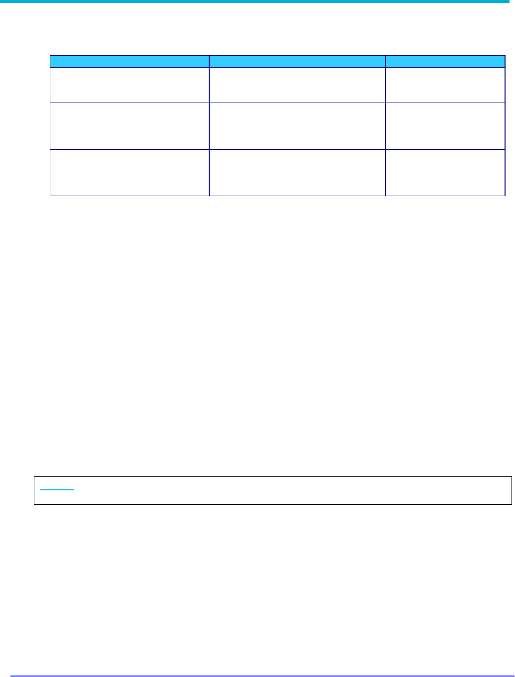
2. Open DPD / DCD file: Follow prompt to select template file to be used and click Open
3. Select screens to be applied and click OK

8G093X01 R6.2
VR Programming Guide
August 2023 Page 36 of 146
4. Write to VR: Select Repeater → Save Changes to APX Repeater
5. Click SAVE and changes are applied to VR
NOTE: A shortcut is available for this process with the File
DPD Files (Templates)
Apply
DPD to APX Repeater. It will launch the process described above from beginning to end.

8G093X01 R6.2
VR Programming Guide
August 2023 Page 37 of 146
Using FRC Off-Line
Viewing Codeplugs Off-Line
1. Launch FRC.
2. From the FRC File menu, select the type of codeplug to be loaded:
• File Legacy Templates (DPD Files) Load DPD Template
• File Templates (DCD Files) Load DCD Template
• File Futurecom Support (EPR Files) Load EPR Support File
2
3. Specify the file location and name when prompted.
4. If saved with custom encryption, enter the corresponding password to load file.
Modifying Codeplugs Off-Line
Once a codeplug is successfully opened (as described in the previous section), the field values
are available for reviewing and modification off-line.
Saving Codeplugs Off-Line
1. After editing the fields, the codeplug file can be saved by selecting
• File → Legacy Templates (DPD Files) → Save DPD Template
• File → Templates (DCD Files) → Save DCD Template
• File → Futurecom Support (EPR Files) → Save EPR Support File
2. Follow prompt to specify a new or the same file name and location.
3. For DPD/DCD files only, enter Personality Name, User Text & date for additional
description about this personality file.
4. Then user can select one of the 2 encryption modes:
• Default: codeplug will be encrypted with a default Futurecom encryption
• Custom: user can enter a password to encrypt the codeplug (EPR/DPD only)
HELPFUL HINT:
If a template file is missing some configurable fields, it may have been created while connected
to a VR with an older firmware version prior to the introduction of those fields.
To update the template file, perform the following steps:
1. Connect FRC to a VR running the most recent version of firmware.
2. Load the template file: File → Legacy Templates (DPD Files) → Load DPD Template
or File → Templates (DCD Files) → Load DCD Template
3. Save a new version of the template file: File → Legacy Templates (DPD Files) → Save
DPD Template or File → Templates (DCD Files) → Save DCD Template
The new template file can now be used off-line and will include previously missing fields.
2
Loaded Futurecom Support EPR File cannot be saved to the repeater

8G093X01 R6.2
VR Programming Guide
August 2023 Page 38 of 146
Applying Firmware to VR
The VR firmware can be flash upgraded/downgraded in the field by following the simple
instructions below:
1. Power up the VR.
2. Create a ‘Firmware’ folder on your computer
3. Download the selected Firmware upgrade file from the Futurecom website.
Home → Support → Documentation and Software → DVR-LX/DVR/VRX1000 →
Firmware Upgrades
4. Unzip the downloaded Firmware file and save the files in this folder.
5. Connect the powered-up DVR / VRX1000 to your computer USB port using the USB
programming cable.
6. Launch Futurecom Repeater Configurator (FRC)
7. Click on the Tools tab on FRC Launcher
8. Click on the Flash Downloader button will launch the Flash Downloader Utility (as shown
below)

8G093X01 R6.2
VR Programming Guide
August 2023 Page 39 of 146
9. Ensure no other program is trying to use the same USB port.
10. Select FileOpen and specify the location of the DVRFirmware.cfg file in the ‘Firmware’
folder
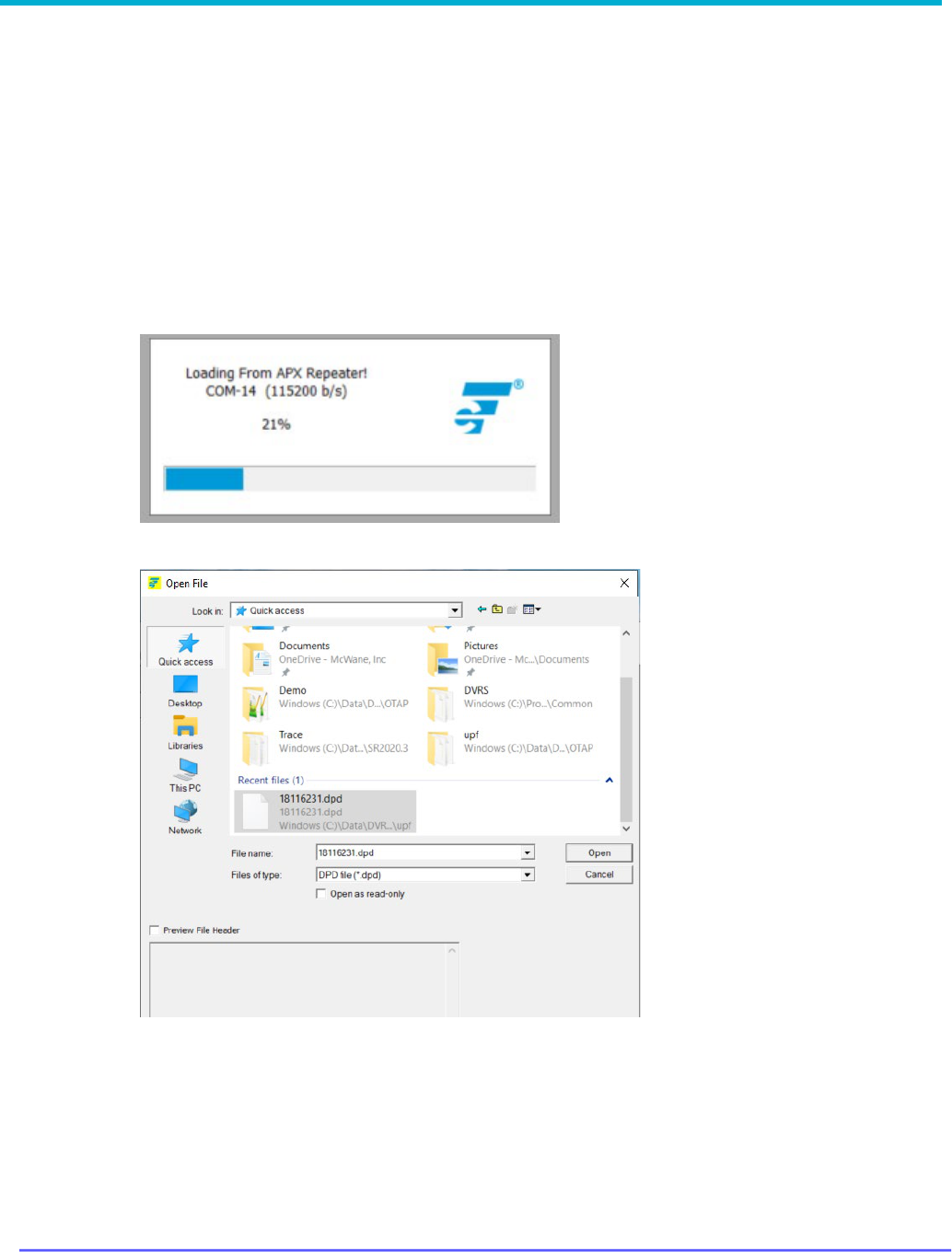
11. Press the ‘Download’ button to start the downloading process.
12. Observe the Application messages and progress. Wait until the download is completed
100% successfully.

8G093X01 R6.2
VR Programming Guide
August 2023 Page 40 of 146

8G093X01 R6.2
VR Programming Guide
August 2023 Page 41 of 146
Upgrading Firmware
Migration from lower to higher version
1. Follow the steps above Applying Firmware.
2. Read VR using FRC
3. FRC will detect that new firmware is running and convert the EEPROM map. User sees
this prompt
4. Will cover the sequences & screenshots in different comment sections for the case of
"Create support backup file" and "Cancel"
5. Following sequences focus on when user click on "Proceed"
6. User will be prompted to ensure DVR is powered on during the conversion process
7. Click "OK" to proceed
8. FRC will start the conversion process, user will see screens opens & closes as
configuration data being converted
9. Upon completion, FRC will show the normal selection panel

8G093X01 R6.2
VR Programming Guide
August 2023 Page 42 of 146
Downgrading Firmware
1. Follow the steps above for Applying Firmware downgrade.
2. Read VR using FRC.
3. FRC will detect that new firmware is running and convert the EEPROM map. User sees
this prompt:
1. See earlier section on the sequences & screenshots for the case of "Create support
backup file" and "Cancel"
2. Click Proceed to continue
3. User will be prompted to ensure VR is powered on during the conversion process
4. Click "OK" to proceed
5. FRC will start the conversion process, user will see screens opens & closes as configuration
data being converted
6. Upon completion, FRC will shows the normal screen selection panel

8G093X01 R6.2
VR Programming Guide
August 2023 Page 43 of 146
VR Programming Guidelines
Programming Steps Overview
The DVRS operation depends on the following:
• VR firmware and programming settings
• MSU firmware and programmed personality
• PSU type, firmware and programmed personality
• System infrastructure
To enable a given VR feature, all the above components must be adequately setup and matched
to support it.
IMPORTANT!
Changes to any of the personality templates may require corresponding adjustments to
the personality templates of the rest of the system components.
To ensure consistent programming of all components, the following programming sequence is
recommended:
Step
Action
Software Program Used
1
Create the MSU template with enabled VR Operation
and save it. Ensure the ‘DVRS profile’ is selected for
the desired MSU Talkgroups / modes and there are
no frequency plan issues (In-band models only).
APX CPS (Motorola)
2
Export an .xml file by using the “DVRS Export” option
in the Motorola CPS (Codeplug Menu). Save the xml
file on your PC.
APX CPS (Motorola)
3
Create a .DCD or .DPD file and program the licensed
VR channels. Ensure the VR frequencies are within
the ordered filtering specification.
FRC (Futurecom)
4
Import the saved .xml file.
FRC (Futurecom)
5
Program the Mobile Channel attributes as required.
FRC (Futurecom)
6
Program the desired analog / digital mode features in
the VR.
FRC (Futurecom)
7
Save the .DCD or .DPD template.
FRC (Futurecom)
8
Create the PSU template. Ensure VR Operation is
Enabled and the settings match those programmed in
the VR.
APX CPS (Motorola)
9
Save the PSU Codeplug.
APX CPS (Motorola)
10
Ensure all personality templates are matched in terms of frequencies, PL / DPL, TX / RX
NAC
s, enabled and disabled features etc. and confirm through testing the DVRS
operation before field deployment.
Table 1 - Recommended Programming Sequence
Additional CPS Programming for VR

8G093X01 R6.2
VR Programming Guide
August 2023 Page 44 of 146
There are several VR related fields located throughout CPS. These fields are divided into three
groups:
• Basic Programming- fields required to enable VR operation with MSU
• Features- fields that enable/disable features
• Fine Tuning- fields to be considered for adjustment during rollout/testing of DVRS
VR Basic Programming
For each field listed below, refer to the CPS help file for field details.
Purpose/Goal
CPS MSU Programming Details
Comments
Enable VR in APX
MSU
DVRS Configuration →
DVRS Wide →
General → DVRS Hardware Enable
Select ‘DVRS Profile’ to
be used in desired MSU
Conventional and/or
Trunking Personalities
Trunking Configuration → Trunking
Personality ‘X’
→ General → DVRS
Profile
Selection → DVRS Profile
AND/OR
Conventional Configuration
→
Conventional Personality ‘Y’
→ General
→
DVRS Profile Selection → DVRS
Profile
Display DVRS button
on MSU Control Head
Radio Ergonomics Configuration →
Controls
→ Menu Items → General →
Conventional Selected Menu Items
→
DVRS
AND/OR
Radio Ergonomics Configuration
→
Controls
→ Menu Items → General →
Trunking Selected Menu Items → DVRS
To be able to control and
change VR mode and
channel from MSU control
head
Assign DVRS button
function to side button
on keypad
microphone
(
OPTIONAL)
Radio Ergonomics Configuration →
Controls
→ Keypad Mic and Accessories
→
General → Conventional Feature →
DVRS
AND/OR
Radio Ergonomics Configuration
→
Controls
→ Keypad Mic and Accessories
→ General → Trunking Feature → DVRS

8G093X01 R6.2
VR Programming Guide
August 2023 Page 45 of 146
VR Feature Programming
For each feature listed below, refer to the Functional Description for a feature description or to
the CPS help file for field details.
Feature
Purpose
CPS MSU Programming
Details
Comments
AVRA
Automatic activation
of VR by external
logic wired to MSU
VIP input
Radio Ergonomics
Configuration → Controls →
Radio VIPs → General → Input
Feature→ DVRS Activation
Additional FRC Configuration:
Hardware Setup →
Use VIP on
Ctl Head
Select polarity of
AVRA logic input
DVRS Configuration →
DVRS Wide → General →
VIP Control of DVRS
ICM
In Car Monitor (ICM)
DVRS Configuration → DVRS
Wide → General → In Car
Monitor → HUB controlled
OR
DVRS Configuration → DVRS
Wide → General → In Car
Monitor → ICM Button/Menu
Controlled
ICM button/Menu
items
Radio Ergonomics
Configuration → Controls →
Control Head ‘X’ → General →
Feature → ICM
and/or
Radio Ergonomics
Configuration → Controls →
Menu Items → General →
Conventional Selected Menu
Items → ICM
AND/OR
Radio Ergonomics
Configuration → Controls →
Menu Items → General →
Trunking Selected Menu Items
→ ICM
Only if ‘ICM
Button/Menu
Controlled’
Selected
for ICM
ICM operation for
each DVRS Profile
DVRS Configuration → DVRS
Profiles → Profile ‘X’ →
General → ICM Allowed
Only if ‘ICM
Button/Menu
Controlled’
Selected
for ICM
REMOTE
ACTIVATION
VR Remote
Activation via Call
Alert from FNE
DVRS Configuration → DVRS
Profiles → Profile ‘X’ →
General → DVRS Remote
Activation → Disabled
OR
DVRS Configuration → DVRS
Profiles → Profile ‘X’ →
General → DVRS Remote
Activation → Via Call Alert
When this feature is
Enabled, the MSU
can no longer initiate
or receive a regular
Call Alert.

8G093X01 R6.2
VR Programming Guide
August 2023 Page 46 of 146
MODE CHANGE
NOTIFICATION
Send a status
message to FNE
after every VR mode
change
DVRS Configuration → DVRS
Profiles → Profile ‘X’ →
General →
Generate Status on
DVRS Mode Change
DVRS Configuration → DVRS
Profiles → Profile ‘X’ →
General → Generate
Status on
DVRS mode Change Holdoff
(sec)
CPS Expert View
only
DVRS Configuration → DVRS
Profiles → Profile ‘X’ →
General → Generate Status
Alternate Mode
CPS Expert View
only
LOCAL
REPEAT/FALLBACK
Outbound FNE Call
Repeat when VR in
Local Mode
DVRS Configuration → DVRS
Profiles → Profile ‘X’ →
General → Local Mode →
Outbound System Repeat in
Local Mode
MSU Mic PTT
transmits to FNE
when VR in Local
Mode
DVRS Configuration → DVRS
Profiles → Profile ‘X’ →
General → Local Mode →
MSU
System PTT in Local Mode
‘Outbound System
Repeat in Local
Mode’ must be
enabled
This field cannot be
enabled at the same
time as ‘Local Tx
Fallback’
Fallback to Local VR
audio repeat when
MSU Mic PTT fails to
transmit to FNE
DVRS Configuration → DVRS
Profiles → Profile ‘X’ →
General → System Mode →
Local Tx Fallback
‘Outbound System
Repeat in Local
Mode’ must be
enabled
This field cannot be
enabled at the same
time as ‘MSU
System PTT in
Local Mode’
MSU SCAN
Suspend Scan on
DVRS Active
DVRS Configuration → DVRS
Profiles → Profile ‘X’ →
General → Suspend Scan on
DVRS Active
8G093X01 R6.2
VR Programming Guide
August 2023 Page 47 of 146
VR Fine Tuning
For each field listed below, refer to the CPS help file for field details.
Purpose/Goal
CPS MSU Programming Details
Comments
Amount of time MSU will transmit a
continuous inbound audio call from
PSU via VR (proxied call)
DVRS Configuration → DVRS Wide →
General
→ Proxy Time Out Timer
(sec)
Amount of time MSU waits for a
busy
conventional channel to be
available to proxy LPSU call
request before denying the request.
DVRS Configuration → DVRS Wide →
General
→ Proxy Limited Patience
(sec)
Amount of time the MSU will stay
on the control channel to proxy a
system response for a given
signaling request from a LPSU.
DVRS Configuration → DVRS Wide →
General
→ Proxy RFSS Response
Time (ms)
CPS Expert View only
P25 Trunking OTAR via VR
For the MSU interfaced to the VR to provide packet data services to associated PSUs on a P25
Trunking system, the MSU must be configured for packet data operation and must be context
activated on the system.
MSU Scan Programming Requirements
The MSU Scan feature is allowed while the VR is active (System or Local Mode) if the MSU
Scan type is configured as one of the following:
• Trunking Scan
• Conventional Scan
• Mixed Conventional Voting Scan
• Legacy Voting Scan
• Multi System Scan
• Priority Monitoring
The MSU does not support any other modes of scan operation, apart from those listed above,
while the VR operates in SYSTEM or LOCAL mode. In such unsupported cases, the MSU will
automatically suspend scan operation when the VR is set to SYSTEM or LOCAL mode of
operation and resume it when the VR is OFF.
NOTE:
The LPSU calls will be repeated on the MSU Selected Channel.
MSU Group Services Programming Requirements
The “Group Text Messaging Service” in the corresponding Trunking system screen has to be
set to ‘Full Decode’ in order to enable the Group Text Feature in the MSU.
To enable the Group Alias Update feature, the MSU must have the ‘OTA Radio Alias Type’ set
to ‘Decode Only’ in the corresponding Trunking system screen.
The MSU may have Group Text Messaging Services and/or Group Alias Update disabled so it
will not store group texts and update its UCL but will still pass along the group texts and alias
updates to the VR and its affiliated PSUs.

8G093X01 R6.2
VR Programming Guide
August 2023 Page 48 of 146
Exporting MSU data (.xml file)
Once the MSU is programmed for DVRS operation, the data needs to be exported by using the
Motorola CPS “DVRS Export” option in the Codeplug menu. The standard CPS Export Data
option cannot be used for DVRS programming purposes.
Programming the PSUs for DVRS Operation
The programming of the PSU depends on the PSU type and user requirements. The following
paragraph describes the programming options related to DVRS operation for the 3 main types
of PSUs – Analog, P25 Digital (Generic), P25 DVRS Enabled.
Certified PSU models have modified firmware that allows them to operate as ‘DVRS Enabled’.
See Futurecom website → Support → Customer Documentation → DVR-LX/DVR/VRX1000 →
Compatibility Chart
https://futurecom.com/upl/downloads/resources/support-
resources/firmware-compatibility-chart.pdffor a list of these certified XTS, APX & APXNext
portables and the corresponding subscriber options required.
All other P25 capable PSU models or the above models with older firmware versions can only be
programmed as ‘P25 Generic’ since they are not capable of enhanced communications with the
VR.
NOTE:
APX MSUs can also be programmed as ‘DVRS Enabled’ and used to communicate through a
VR provided they are NOT interfaced to a VR.
Programming the P25 ‘DVRS Enabled’ PSU
The P25 ‘DVRS Enabled’ PSU needs to be affiliated on the P25 FNE through the VR therefore
its ASTRO Unit ID and TG ID must be valid and allowed on the FNE side.
Typically, the conventional ASTRO PSU Unit ID is set to match that of the Trunking system PSU
ID in in-band applications. In cross-band application the ASTRO PSU unit ID must be enabled in
the P25 system to be able to affiliate and communicated through the VR.
If Fireground (FG) signaling is enabled in the PSU, ensure that the programmed “Tx Voice
Type” (analog or digital) matches the type of corresponding VR “FG Enabled” channel (analog
or digital).
XTS Series ‘DVRS Enabled’ PSUs
If the XTS DVRS Enabled PSU needs to support say 10 TGs via VR, then the PSU needs to be
programmed with 10 different conventional ASTRO personalities using the designated DVRS
Enabled ASTRO system. Each conventional personality must be strapped to the corresponding
TG ID from the specified TG List. Each conventional personality is then assigned to a desired
PSU mode in the Zone / Channel assignment listing. The PSU behavior, when switched to a VR
channel, is specified by programming the desired features in the corresponding ASTRO system
‘DVRS’ Tab. Alternatively the PSU can be programmed with just one (or a few TG IDs) and TG
translation can be enabled in the VR so that the PSU TG ID is always translated to the ID of the
TG selected on the MSU control head.
NOTE: TG IDs are programmed in the XTS PSU conventional ASTRO Talkgroup List in decimal
format.

8G093X01 R6.2
VR Programming Guide
August 2023 Page 49 of 146
IMPORTANT!
The PSU and VR PL/DPLs must be programmed to be properly matched. The DVRS Enabled
PSU must be programmed for mixed receive to program PL on a DRVS Enabled Channel.
APX Series ‘DVRS Enabled’ PSUs
If Group Services support is required, the “Group Text Messaging Service” in the corresponding
conventional system screen must be set to ‘Full Decode’ to enable the Group Text Feature. To
enable the Group Alias Update feature, the PSU must have the ‘OTA Radio Alias Type’ set to
‘Decode Only’ in the corresponding conventional personality screen. ‘Selective Squelch’ needs to
be programmed (instead of the default ‘Normal Squelch’) if the PSU User want to receive only
Group Services for its selected Talkgoup.
If the APX ‘DVRS Enabled’ PSU needs to support say 10 TGs via the VR, then the PSU may be
programmed with a single Conventional Personality, which is using a Conventional System of
‘DVRS’ type. The Conventional Personality’s Frequency Option table will contain 10 entries, which
are strapped to desired TG IDs. The actual TG IDs are specified in the designated Astro Talkgroup
List, which is then linked to the Conventional Personality (‘Astro Talkgroup’ tab). The PSU
behavior, when switched to a VR channel, is specified by programming the desired features in
the corresponding Conventional System ‘DVRS’ Tab. Each Frequency option of the Conventional
Personality (using desired TG ID and a ‘DVRS’ type Conventional System) is then assigned to a
PSU mode in the Zone Channel Assignment listing. Alternatively, the PSU can be programmed
with just one (or a few TG IDs) and TG translation can be enabled in the VR so that the PSU TG
ID is always translated to the ID of the TG selected on the MSU Control Head.
Programming of Generic P25 PSU for Digital VR Mode
The programming of a Generic P25 PSU requires matched VR – PSU programming of:
• VR Tx and Rx Frequencies
• Tx and Rx NACs
In addition, the programmed PSU ASTRO Unit ID and selected TG ID must be valid and allowed
on the P25 system.
Programming of the P25 PSU (Generic P25 or ‘DVRS Enabled’) for operation on
Conventional P25 MSU System
Both PSU types must have the Tx and Rx NACs matched with those programmed in the VR. If
the P25 conventional system is not using dedicated TG IDs then all system radios transmit with
the default TG ID = 1.
When the XTS PSU is programmed as ‘DVRS Enabled’, and ‘Talkgroup’ is checked in the given
conventional personality, the PSU transmits with default TG ID = 2. When the system radios are
operating on a conventional P25 system, which is not using Talkgroups, all radios still transmit
with default TG ID = 1. Therefore, the ‘DVRS Enabled’ PSU programming may need to be
changed to TG ID=1 to match the rest of the system radios so that communications can be heard
between ‘DVRS Enabled’ PSUs and system PSUs. The Generic P25 PSU transmits with default
TG ID = 1 so it matches the rest of the system radios and its programming does not need to be
changed.

8G093X01 R6.2
VR Programming Guide
August 2023 Page 50 of 146
NOTE:
TG ID 1 can be added to the VR Translation tables so that PSU calls coming from Generic P25
PSUs (with TG ID 1) will be translated to the TG ID currently selected on the MSU, while ‘DVRS
Enabled’ PSUs will be able to make proxied calls on their selected TG IDs.
If the conventional P25 system is using dedicated TG IDs, then the ‘DVRS Enabled’ or Generic
P25 PSU must be programmed with corresponding conventional personalities using the required
TG IDs.
Programming of the P25 XTS PSU (Generic P25 or ‘DVRS Enabled’) for Inbound Digital
Takeover
A Generic P25 XTS PSU must have Smart PTT disabled if “Outbound Takeover by Voice Allowed”
is enabled in the VR.
Programming of Analog Conventional PSU for Analog VR Mode
The programming of any PSU for analog mode involves the following:
• PSU Tx frequency and Tx PL/DPL must match the VR Rx frequency and Rx PL / DPL.
• PSU Rx frequency and Rx PL/DPL must match the VR Tx frequency and Tx PL / DPL.
• Adjacent channel spacing programming of the VR channel and PSU must be the same i.e.
either 12.5kHz or 25kHz.
• If MDC Emergency is to be used by the PSU, the PSU must have MDC1200 signaling
enabled. The MDC1200 System Pretime must be set to 50ms if the PSU Emergency ID is to
be seen on other System radios that are on the same TG. If the MSU has the default System
Pretime of 700ms, the PSU Emergency ID will only be displayed on the Dispatcher Console.
• Preamble during pretime must NOT be enabled.
• If MDC1200 Emergency alarm is used when the MSU is on a trunked channel, the MDC ID
(hex) must be allowed on the Trunking system side (see MDC PTT ID offset)
• If DTMF signaling is used, the DTMF sequence programmed in the PSU must end with a ‘*’
i.e., 123*.

8G093X01 R6.2
VR Programming Guide
August 2023 Page 51 of 146
Feature Programming
How to Program GPS Driven Deactivation Feature
Step 1: Ensure GPS Feature license has been purchased and applied to VR.
Step 2: Determine how feature will be used (Scenario)
3
1. GPS Deactivate Only
A. Speed only
B. Distance only
C. Speed or Distance
D. Speed and Distance
2. AVRA Activate with GPS Deactivate
A. Speed only
B. Distance only
C. Speed or Distance
D. Speed and Distance
3. AVRA Activate with AVRA or GPS Deactivate
A. Speed only
B. Distance only
C. Speed or Distance
D. Speed and Distance
4. AVRA Activate with AVRA followed by GPS Deactivate
A. Speed only
B. Distance only
C. Speed or Distance
D. Speed and Distance
Step 3: Open the Hardware Setup window
3
Refer to VR Functional Description: GPS Driven Deactivation for details on this feature.

8G093X01 R6.2
VR Programming Guide
August 2023 Page 52 of 146
Step 4: Configure field values as indicated below for the identified scenario in Table 2, GPS
Driven Deactivation Scenarios, below.

8G093X01 R6.2
VR Programming Guide
August 2023 Page 53 of 146
Table 2 - GPS Driven Deactivation Scenarios
FRC
FIELD
SCENARIO (from Step 2 above)
1A
1B
1C
1D
2A
2B
2C
2D
3A
3B
3C
3D
4A
4B
4C
4D
AVRA/GPS
Tone
Optional
Automatic
VR
Activation
AVRA
Function
Activ-
ate only
Activ-
ate only
Activ-
ate only
Activ-
ate only
Activate
/ Deact
-
ivate
Activate
/ Deact
-
ivate
Activate
/ Deact
-
ivate
Activate
/ Deact-
ivate
Activate
/
Deact-
ivate
Activate
/ Deact-
ivate
Activate
/ Deact-
ivate
Activate
/ Deact-
ivate
GPS Driven
Deactivation
Must be selected for all scenarios
Speed
Speed
Threshold
User
Value
User
Value
User
Value
User
Value
User
Value
User
Value
User
Value
User
Value
User
Value
User
Value
User
Value
User
Value
Speed Units-
mph or km/h
User
Value
User
Value
User
Value
User
Value
User
Value
User
Value
User
Value
User
Value
User
Value
User
Value
User
Value
User
Value
Distance
Distance
Threshold
User
Value
User
Value
User
Value
User
Value
User
Value
User
Value
User
Value
User
Value
User
Value
User
Value
User
Value
User
Value
Distance
Units
- feet or
meters
User
Value
User
Value
User
Value
User
Value
User
Value
User
Value
User
Value
User
Value
User
Value
User
Value
User
Value
User
Value
Threshold
Logic
OR
AND
OR
AND
OR
AND
OR
AND
Deactivate
Upon
AVRA
or
GPS
AVRA
or
GPS
AVRA
or
GPS
AVRA
or GPS
AVRA
Follow
by GP
S
AVRA
Follow
by GP
S
AVRA
Follow
by GPS
AVRA
Follow
by
GPS
Primary /
Secondary
Preference
None or Stationary based on desired behaviour
4
NOTE: Field names in italics are descriptions of the fields that have no titles on the FRC Hardware Setup window.
Step 5: For Scenarios 4A-4D which involve “Deactivate Upon: AVRA Followed by
GPS”
5
, there is an additional configuration option which will allow an AVRA trigger only
to deactivate the VR upon loss of GPS signal:
• Check box “Fallback to AVRA when no GPS signal”
• enter desired timer value
Step 6: Be sure to test VR operation before implementing VR wide.
4
Refer to Primary / Secondary Feature Document for details on this feature.
5
Refer to VR Functional Description: GPS Driven Deactivation for details on this feature.

8G093X01 R6.2
VR Programming Guide
August 2023 Page 54 of 146
How to Program NAC Linking Feature
Step 1: In the Repeater Channel Setup window, select the desired option for the VR channel
under the NAC Linking field. (scroll to far right).
Step 2: Use FRC copy data feature to quickly apply the same configuration any additional
channels.
NOTE: Only Digital or Forced Analog Channel Type support this feature. For all other channel
types, this feature must be disabled.
Step 3: Add any restricted NACs to the PSU NAC Table. May include a range of NACs or
individual NACs.
Step 4: Enable the PSU "DVR Sync NAC Matching" field. This field can be found in the CPS
tool: Conventional Configuration → Conventional System → DVRS set of fields.

8G093X01 R6.2
VR Programming Guide
August 2023 Page 55 of 146
How to Program TPS Signaling
FRC – VR Programming
Step 1: Open Repeater Channel Setup window
Step 2: Set Channel Type to TPS
Step 3: Set PL and NAC values to match with PSU programming: Rx PL(Hz), Tx PL(Hz), PL
STE(deg.), Rx NAC(h), Tx NAC(h)
CPS – MSU and PSU Programming for TPS Signaling
Prerequisite for MSU only – ensure DVRS profile is set in the conventional personality, then
proceed with the steps below.
Step 1: Conventional System → Set System Type to ASTRO
Step 2: Conventional Configuration → Conventional Personality:
a) RX Options → RX Voice/Signal Type → Mixed Mode
b) TX Options → TX Voice/Signal Type → ASTRO
c) Signaling → ASTRO → ASTRO System → set to selected profile
d) Signaling → Non-ASTRO → Signaling Type → None
e) ASTRO Talkgroup → Talkgroup → Unchecked
f) Features → Incident Signaling Type → Tactical Public Safety
g) Features → Tactical Public Safety UI Enable → Checked
Step 3: Under Radio Wide → Tactical Public Safety there are additional parameters that may be
configured as per user preference. Refer to Motorola documentation for further
information.

8G093X01 R6.2
VR Programming Guide
August 2023 Page 56 of 146
How to Program Talkgroup Matching
FRC - VR Programming
Step 1: Open the Digital Setup window.
Step 2: Check the Enforce TG Matching field.
Additional Notes
The PSU displays “TG mismatch” when this feature is enabled and the PSU talkgroup does not
match the MSU talkgroup.

8G093X01 R6.2
VR Programming Guide
August 2023 Page 57 of 146
How to Program Talkgroup Proxying
FRC - VR Programming
Step 1: Open the Digital Setup window.
Step 2: Confirm the Enforce TG Matching field is unchecked.

8G093X01 R6.2
VR Programming Guide
August 2023 Page 58 of 146
CPS - PSU Programming for Talkgroup Proxying
Step 1: Create a new ASTRO Talkgroup List
• Conventional Configuration → ASTRO Talkgroup List → New List
• New List → Talkgroup List → add a record for each PSU talkgroup
Step 2: Update the Conventional Personality, Conventional Personality
• Signaling → ASTRO → ASTRO Rx Unmute Rule → Selective Squelch
• ASTRO Talkgroup → Talkgroup → checked
• ASTRO Talkgroup → Talkgroup List → New List
• ASTRO Talkgroup → Selection Type → Strapped (preferred over Selectable)
• Frequency Options → create a record for every PSU talkgroup
Each record will have same Rx/Tx frequency info
ASTRO Talkgroup ID → select the appropriate PSU talkgroup for each
record
Step 3: Update the Zone Channel Assignment
• Add a new VR channel record for each PSU talkgroup
• Channels → Personality → Conventional Personality for each record
• Channels → Conventional Frequency Option → select the appropriate PSU
talkgroup for each record
Additional Notes
1. Deployment: It is recommended to set the MSU to a talkgroup that is never used to
ensure the talkgroup is always available when needed. If it is set to a commonly used
talkgroup, when a user is in range and presses PSU PTT, they would get a deny tone if
the talkgroup is busy.
2. Programming: For Step 2, Strapped is the preferred configuration. However, if desired,
Selectable may be set instead and then Step 3 is not required. Please note that the
Selectable option requires the end user to follow a two-step process to change
talkgroups: change selector button for PSU channel, and then enter menu to select
talkgroup.

8G093X01 R6.2
VR Programming Guide
August 2023 Page 59 of 146
How to Program Talkgroup Translation
FRC - VR Programming
Step 1: Open the Digital Setup window.
Step 2: Confirm that the Enforce TG Matching field is unchecked.
Step 3: Open the TG Translation Table window.
Step 4: Add the PSU talkgroup ID to be used for translation.
NOTE: Talkgroup(s) must be outside of range of talkgroups used on the Trunking System.

8G093X01 R6.2
VR Programming Guide
August 2023 Page 60 of 146
CPS - PSU Programming for Talkgroup Translation
Step 1: Create a new ASTRO Talkgroup List
• Conventional Configuration → ASTRO Talkgroup List → New List
• Add a new record for the PSU talkgroup ID that will not be used → Translation
talkgroup
o MUST MATCH TG ID ENTERED INTO THE TG TRANSLATION TABLE
o MUST MATCH TG ID MODE - DEC/HEX
Step 2: Update the Conventional Personality, Conventional Personality
• Signaling → ASTRO → ASTRO Rx Unmute Rule → Normal Squelch
• ASTRO Talkgroup → Talkgroup → checked
• ASTRO Talkgroup → Talkgroup List → New List
• ASTRO Talkgroup → Selection Type → Strapped (preferred over Selectable)
• Frequency Options → create a record for the translated PSU talkgroup
o ASTRO Talkgroup ID → Translation talkgroup
Step 3: Update the Zone Channel Assignment
• Add a new VR channel record for the translated PSU talkgroup
• Channels → Personality → Conventional Personality
• Channels → Conventional Frequency Option → Translation talkgroup
Additional Notes
1. Programming: PSU talkgroup(s) to be used for the Talkgroup Translation feature must be
outside the range of talkgroups used on the Trunking system.
2. Programming: PSUs need to be programmed with Normal Squelch to hear outbound calls
(system originated calls) or MSU microphone PTT calls as they will be repeated on the
MSU talkgroup- no translation in this direction. Normal Squelch ignores conventional
talkgroups.
3. Programming: PSUs can be programmed with just one talkgroup ID which significantly
reduces the amount of required programming when the PSU needs access to many
talkgroups. It also means only one zone/channel for the portable user which simplifies
operation.
4. Generic (Non-DVRS Enabled) PSUs: When not configured for conventional talkgroup
operation, P25 PSUs use talkgroup ID 1 by default when transmitting. If TG ID 1 is added
to the VR Translation table, then PSUs transmitting TG ID 1 will be translated to the
talkgroup selected on the MSU.
5. Programming: For Step 2, Strapped is the preferred configuration. However, if desired,
Selectable may be set instead and then Step 3 is not required. Please note that the
Selectable option requires the end user to follow a two-step process to change talkgroups:
change selector button for PSU channel, and then enter menu to select talkgroup.

8G093X01 R6.2
VR Programming Guide
August 2023 Page 61 of 146
Talkgroup Translation Table
When the local PSU transmits on a TG that is in the VR Translation table, the call will be
transmitted on the TG currently selected on the MSU control head. The local PSUs must be
programmed with Normal squelch or NAC=F7E to be able to receive outbound (system) or MSU
Mic PTT calls when TG Translation is enabled. The TG Translation Table allows the user to
program the Local PSU TG IDs that are enabled for TG Translation. The default list is empty, i.e.,
TG translation is disabled.
To enter a single entry into TG Translation Table, user can enter ‘--' in the end column.
IMPORTANT!
The VR Translation table (and corresponding PSU programming) must not contain TG IDs
that are used by the trunked FNE side.

8G093X01 R6.2
VR Programming Guide
August 2023 Page 62 of 146
How to Program Unit ID Translation
FRC- VR Programming
Step 1: Open the Digital Setup window.
Step 2: Confirm that the Enforce TG Matching field is unchecked.
Step 3: Open the Repeater Channel Setup window.
Step 4: Scroll to the far right and set the UID TRNSL. field to Yes for each required channel.
Additional Notes
1. Programming- only applicable to digital channels.
2. Programming- overrides Talkgroup Proxying and Translation features.
3. Programming- incompatible with PSU Authentication feature.
4. Programming- incompatible with Data Services and PSU Authentication.

8G093X01 R6.2
VR Programming Guide
August 2023 Page 63 of 146
How to Program Emergency Revert
For a Trunking System
Step 1: Mobile CPS → Emergency Configuration → Trunking Emergency Profiles → General
→ Emergency Talkback set to Revert
Step 2: Mobile CPS → Trunking Configuration → Trunking Personality → General → Trunking
Emergency Profile Selection set to Profile configured in Step 1
Step 3: Mobile CPS → Trunking Configuration → Trunking Personality → General →
Emergency Revert Type set to Talkgroup Revert or System Revert, depending on
desired configuration.
(continue with either Talkgroup or System Revert Configuration as outlined below)
For Talkgroup Revert Configuration
Step 4: Mobile CPS → Trunking Configuration → Trunking Personality → General →
Emergency Talkback Revert → Talkgroup ID set to desired ID
Step 5: Using FRC, import the Motorola file with the above configuration.
Step 6: FRC → Mobile Radio Channel Setup → Emergency Rev. Item# → set to Item #
that corresponds to the desired zone/channel to be used for Emergency
alarms/calls
Step 7: FRC → Emergency Setup → Emergency Cancel → Timeout set to desired
value
NOTE: If Timeout is set to OFF, MSU behaviour is different for an Emergency Alarm vs
Call. Refer to Emergency Setup → Emergency Cancel → Timeout for
details.

8G093X01 R6.2
VR Programming Guide
August 2023 Page 64 of 146
For System Revert Configuration
Step 4: Mobile CPS → Trunking Configuration → Trunking Personality → General →
Emergency System Revert → Revert Zone set to desired zone
Step 5: Mobile CPS → Trunking Configuration → Trunking Personality → General →
Emergency System Revert → Revert Channel set to desired channel
Step 6: Using FRC, import the Motorola file with the above configuration.
Step 7: FRC → Mobile Radio Channel Setup → Emergency Rev. Item# → displays the
Item # associated with the zone/channel programmed in Step 4/5
Step 8: FRC → Emergency Setup → Emergency Cancel → Timeout set to value
NOTE: If Timeout is set to OFF, MSU behaviour is different for an Emergency Alarm vs
Call. Refer to Emergency Setup → Emergency Cancel → Timeout
For a Conventional System
Step 1: Mobile CPS → Conventional Configuration → Conventional System → General →
Emergency Profile set to an existing Emergency Profile.
Step 2: Mobile CPS → Conventional Configuration → Conventional Personality → Signaling →
Emergency Revert → Revert Type set to Revert Channel.
Step 3: Mobile CPS → Conventional Configuration → Conventional Personality → Signaling →
Emergency Revert → Revert Zone set to desired zone
Step 4: Mobile CPS → Conventional Configuration → Conventional Personality → Signaling →
Emergency Revert → Revert Channel set to desired channel.
Step 5: Using FRC, import the Motorola file with the above configuration.
Step 6: FRC → Mobile Radio Channel Setup → Emergency Revert → displays zone/channel
programmed in Step 3/4.

8G093X01 R6.2
VR Programming Guide
August 2023 Page 65 of 146
Step 7: FRC → Emergency Setup → Emergency Cancel → Timeout set to desired value
NOTE: If Timeout is set to OFF, MSU behaviour is different for an Emergency Alarm vs Call.
Refer to Emergency Setup → Emergency Cancel → Timeout for details.

8G093X01 R6.2
VR Programming Guide
August 2023 Page 66 of 146
FRC Window and Field Definitions
Documentation Conventions
The following table provides information on conventions used throughout the document
.
Convention
Description
Examples
Window
Name→Field
Name
Used through field descriptions to refer
to a specific FRC field on a specific FRC
window
Repeater Info → Personality Name refers
to the Personality Name field located on
the Repeater Info Window
Vertical
Field
Name
Field grouping / Box title for a set of
fields logically grouped together on an
FRC window
Repeater Info → Date of Programming is
the group name for the following fields:
DAY, MONTH, YEAR
Range
Valid values allowed for a field with units
of measurement (where appropriate) and
default value identified where default
value exists
Repeater Info → Personality Name:
Maximum 14 alphanumeric characters
Repeater Channel Setup → Tx Pwr: 20-
40 dBm
Bold Text in
Range Column
Factory default value
Repeater Channel Setup → Tx Pwr: 20-
40 (30) dBm
Italic Field
Names
Fields displayed without a title / label
Hardware Setup → Speed Threshold
15 is the Speed Threshold value for the
Speed Field
Description
Explains what the field represents and
provides details on each field value
where appropriate
Mobile Radio Channel Setup → TG
Mode: Enables or Disables Slaving of the
VR Mode to the selected TG.
‘None’ this selection assumes no
specific VR Mode is linked to the TG. The
VR stays in the last mode or the Mode
associated with the VR Channel.
‘Local’ / ‘System’ This selection
forces the VR Mode to change to either
Local or System respectively upon
selection of the TG.
‘User’ The Last VR Mode that was
selected by the User is in effect and the
User can change it as required.
‘Disabled’ VR is Disabled when this
TG is selected.
‘OFF’ VR is in OFF mode when this
TG is selected.
Notes
Restrictions / limitations related to the
programming of the field; identifies
dependencies on other fields, or if a
feature license is required
Repeater Channel Setup → PSU Scan
Must be enabled on all Repeater
Channels that will be used by PSUs with
Conventional Scan option enabled.
Feature License - PSU Conventional
Scan required for this field to be editable.
Refer to VR Ordering Guides for order
code
Mobile Radio Channel Setup →
Emergency Revert
This field will be marked red (invalid) if it:

8G093X01 R6.2
VR Programming Guide
August 2023 Page 67 of 146
• Points to MSU channel, which TG
Mode is "Disabled"
• Points to a ‘VR Disabled’ zone and
channel
•
Points to an MSU channel, which
does not have the current VR channel
in the list of allowed VR channels
Blue, Italic,
Bold text in
Notes column
Feature license required for this field to
be editable.
Repeater Channel Setup → PSU Scan
Feature License - PSU Conventional
Scan required for this field to be editable.
Refer to VR Ordering Guides for order
code
Field Name*
VR model specific fields
Mobile Radio Channel → Mob. Det*
Identified as *VRX1000 ONLY field in the
Notes column
Field Name ¤
Fields that are only applicable to the
connected VR
These fields will NOT be propagated in
the template file (DPD or DCD) or Radio
Manager
These fields are greyed out during offline
editing except for Hardware/Software
Info screen
VR Common Setup → This VR
ID¤
ID of the connected VR
Field Name ●
Fields that are only applicable to the
installed FRC and stored locally on its
PC
These fields will NOT be propagated in
the template file (DPD or DCD)
Ports → COM Port ●
COM Port setting specific to the version of
FRC installed on the PC
Greyed Out
(Disabled)
Fields
Greyed out fields cannot be edited.
Two scenarios exist:
1) Parameters displayed are ignored by
VR either due to licensing, or
configuration of other fields.
2) Parameters displayed are fixed
based on VR unit hardware/software.
Examples:
1) Observed with GPS Driven
Deactivation
2) Observed with Hardware/Software
info

8G093X01 R6.2
VR Programming Guide
August 2023 Page 68 of 146
Options
Ports
Field Name
Range
Description
Notes
COM Port
●
N/A
Automatically selected and used
when connecting directly to the
VR USB Port.
The save icon sets the
selected COM port as
the default USB Port so
it is the first port
accessed for any
read/write operation.
DVRS Port ●
Read Only
Automatically assigned field.
Programming
Mode for MSU ●
Yes
No
When set to ‘Yes’ the MSU is
placed into programming mode
whenever the V
R is being
programmed.
When set to ‘No’ the MSU is still
fully functional while the VR is
being programmed.
The save icon saves the
selected setting (yes or
no) as a default on this
FRC.

8G093X01 R6.2
VR Programming Guide
August 2023 Page 69 of 146
Repeater Setup
IMPORTANT!
Do not change VR settings unless knowledgeable with specific options. The Futurecom
Repeater Configurator (FRC) program reports any obvious errors and does not allow
invalid data to be saved to the VR, however, not all inconsistencies can be reported by the
FRC. Successful DVRS programming requires thorough understanding of the VR, MSU
and PSU programming, as well as specific User/System requirements. DVRS will operate
properly only when all templates (VR, MSU and PSU) are matched. E.g.: changing APX
MSU template may require an update of VR template, which in turn may require update of
PSU template.
RF / Analog Setup
The values in this window are set to the correct settings upon shipping from the Futurecom factory.
No changes to those values are required unless instructed otherwise by Futurecom.
Frequency Band Setup
This screen is used for selecting the adjacent channel separation. Three selections are possible
– Set 1, Set 2 & Set 3, which can be either Narrowband (12.5kHz / 1.5kHz) or Wideband (25kHz
/ 3kHz) or NPSPAC (25KHz / 4kHz). Ensure the correct spacing (Set 1 or Set 2 or Set 3) is
selected to match the portable radio programming on each VR channel – see “Repeater Channel
Setup” screen, ‘Bandwidth’ field.
Rx/Tx Synthesizer Frequency Step field indicates the allowable step size of frequencies within
the frequency band.
• VHF- 2.5, 5, 6.25 kHz
• UHF- 6.25 kHz
• 700MHz- 6.25 kHz
• 800MHz- 6.25 kHz

8G093X01 R6.2
VR Programming Guide
August 2023 Page 70 of 146
Repeater Info
This screen is provided for template maintenance purposes. The VR personality templates can
be dated and referenced from this Menu screen by entering an applicable template / project
description and revision.
Field Name
Options /
Units
Description
Notes
Date of Programming
Day
2 digits
Indicates the day for the date of
programming for this personality
template.
Month
2 digits
Indicates the month for the date of
programming for this personality
template.
Year
2 digits
Indicates the year for the date of
programming for this personality
template.
Personality Name
Maximum 14
alphanumeric,
characters
Name used to reference this
personality template.
VR User Text
Maximum 32
alphanumeric,
characters
Informational text to differentiate
this configuration from other
Repeater installations such as
County name, Chief’s vehicle, Fire
Engine 49 etc.
Set Repeater
Password
Set Password for the Repeater
Reset Repeater
Password
Reset the Repeater Password.
Tier Level*
Tier 1
Tier 2
Tier 3
VRX1000 Operation Mode
*VRX1000 ONLY field
See table below
Feature Licenses
Authentication
¤
Enabled /
Disabled
Showing the status of the Feature
License required to enable
Authentication functionality
Feature License -
Authentication required to
enable this feature. Refer to
VR Ordering Guides
RM-OTAP
¤
Enabled /
Disabled
Showing the status of the Feature
License required to enable Over
the Air Programming functionality
Feature License - RM-
OTAP required to enable this
feature. Refer to VR Ordering
Guides
PSU
Conventional
Scan ¤
Enabled /
Disabled
Showing the status of the Feature
license required to enable PSU
Scan functionality.
Feature License - PSU
Conventional Scan required
to enable this feature. Refer
to VR Ordering Guides
SmartConnect
Extension ¤
Enabled /
Disabled
Showing the status of the Feature
license required to enable
SmartConnect In-Vehicle Range
Extension
Feature License –
SmartConnect In-Vehicle
Range Extension required
to enable this feature. Refer
to VR Ordering Guides
GPS Driven
Deactivation ¤
Enabled /
Disabled
Showing the status of the Feature
license required to enable GPS
Driven Deactivation
Feature License – GPS
Driven Deactivation
required to enable this
feature. Refer to VR Ordering
Guides

8G093X01 R6.2
VR Programming Guide
August 2023 Page 71 of 146
‘Tier’ level of the VRX1000 indicates the features sets supported by the VRX1000*
Tier Order Option VRX1000 Feature sets supported
Tier 1
N.A.
(Included with
VRX1000)
Enabled by default on any VRX1000 model and supports the
following operation:
•
Analog Only Operation OR VRS750 Compatibility Mode
Tier 2
P25 Operation
Add-on Option to Tier 1 providing the following additional
capabilities:
• P25 Digital for use on P25 Conventional FNE
• P25 Digital for use on P25 Trunked (FDMA) FNE without
support of Enhanced Trunking features (used with Generic
P25 PSUs)
Tier 3
P25 Enhanced
Trunking Features
P25 Encryption
Add-on Options to Tier 2. Include the following additional
capabilities:
•
Forced Analog Operation for use on P25 Trunked TDMA
FNE Or non-P25 FNE (such as Type II Trunking). Requires
‘DVRS Enabled’ PSUs.
•
P25 Digital for use on P25 Conventional FNE.
•
P25 Digital for use on P25 Trunked (FDMA) FNA including
Enhanced Trunking features. Supports ‘DVRS Enabled’
PSUs and associated enhanced Trunking features.
•
enables P25 Encryption pass through VRX1000

8G093X01 R6.2
VR Programming Guide
August 2023 Page 72 of 146
Hardware / Software Info
This screen is for information only and it displays the firmware revisions, model and serial number
of the VR.
Update Info
This screen is for information only
Field Name
Options /
Units
Description
Notes
Local Configuration ¤
Name
for future use
Timestamp
for future use
Access Time
alphanumeric
characters
Indicates the time on when
the repeater’s configuration
was programmed locally
CRC
for future use
Local Firmware ¤
Name
for future use
Timestamp
for future use
Access Time
alphanumeric
characters
Indicates the time on when
the repeater’s firmware was
updated locally
CRC
for future use
OTAP Configuration ¤
Name
alphanumeric
characters
Indicates template name of
the last configuration set
(DCD file) that was pushed
via Motorola Radio
Management.
Can give a dcd file a
Template name which
appears in DVRS Fileview in
RM → Config Data Name
Timestamp
alphanumeric
characters
Indicates the timestamp on
when the configuration set
was created
Format: YYYYMMDD-
HHMMSS
Access Time
for future use
CRC
alphanumeric
characters
Indicates the checksum of
the configuration set pushed
via Motorola Radio
Management
OTAP Firmware ¤
Name
alphanumeric
characters
Indicates name of the
firmware bundle that was
pushed via Motorola Radio
Management
Timestamp
alphanumeric
characters
Indicates the timestamp on
when the firmware bundle
was created
Format: YYYYMMDD-
HHMMSS
Access Time
for future use
CRC
alphanumeric
characters
Indicates the checksum of
the firmware bundle pushed
via Motorola Radio
Management

8G093X01 R6.2
VR Programming Guide
August 2023 Page 73 of 146
Field Name
Options /
Units
Description
Notes
Last
Configuration ¤
MSU
Local
Indicate the source of the
configuration set:
MSU – configuration is
programmed via Motorola
Radio Management
Local – configuration is
programmed locally via
Futurecom Repeater
Configurator
Last Firmware ¤
MSU
Local
Indicate the source of the
firmware:
MSU – firmware is
programmed via Motorola
Radio Management
Local – firmware is
programmed locally via
Futurecom Repeater
Configurator
Reload OTAP
Configuration
from MSU
Command button to apply
the last DCD file sent via
RM-OTAP
Feature License - RM-
OTAP required to enable
this feature. Refer to VR
Ordering Guides for order
code
Reload OTAP
Firmware from
MSU
Command button to apply
the last Firmware version
sent via RM-OTAP
Feature License - RM-
OTAP required to enable
this feature. Refer to VR
Ordering Guides for order
code

8G093X01 R6.2
VR Programming Guide
August 2023 Page 74 of 146
Personality Data
This section covers the VR channels setup along with the features set required for the various
operation scenarios.
Repeater Channel Setup Window
Field Name
Options / Units
Description
Notes
Ch #
1 to 192
VR Channel Number –
referenced in the Mobile Radio
Channel Setup when
associating VR channels to
Mobile Radio Modes.
Read Only Field.
Name
Seven (7) character
string
VR Channel name (alias)
displayed on the Control Head
when the VR is enabled.
Channel
Mode
F. Duplex
Simplex
Determines the VR mode of
operation for the specific
channel – Full Duplex or
Simplex.
F. Duplex not available for
VRX1000
Simplex Operation is not
compatible with
Rackmount Booster PA.
Fire
Ground
Yes / No
Enables or Disables Fireground
Signalling Capabilities on the
selected VR channel.
Fireground (FG) signaling
can be enabled on analog
or digital VR channels
only.
Channel
Type
Digital
Analog
Mixed
F. Analog
TPS
FA-All
Defines the VR Channel Type.
Mixed Mode is selected when
the same VR channel will be
used by Analog and P25 PSUs.
• Only Analog and TPS
supported with Tier 1
VRX1000
• Only Digital, Analog,
Mixed and TPS
supported with Tier 2
VRX1000
• All channel types
supported with Tier 3
VRX1000
Rx Freq*
[MHz] Dependent on
DVR band
DVR Rx Frequency
(Must match the PSU Tx
Frequency).
*DVR ONLY field
Rx Frequency is the same
as the programmed Tx
frequency when
programmed in Simplex
mode
Rx PL
[Hz] / DPL
VR Rx PL / DPL
(Must match the Analog PSU
Tx PL / DPL).
Applies to Analog, Mixed
and F. Analog Mode Only.
Tx Freq*
[MHz] Dependent on
DVR band
DVR Tx Frequency
(Must match the PSU Rx
Frequency).
*DVR ONLY field
Splx Freq*
[MHz]
VRX1000 Simplex Rx / Tx
Frequency
(Must match the PSU Rx / Tx
Frequency).
*VRX1000 ONLY field
Tx PL
[Hz] / DPL
VR Tx PL / DPL (Must match
the Analog PSU Rx PL / DPL).
Applies to Analog, Mixed
and F. Analog Mode Only.
PL STE
[deg] / DPL
Analog PSU PL / DPL Squelch
Tail Elimination – must be
programmed to match the PSU.
Applies to Analog, Mixed
and F. Analog Mode Only.

8G093X01 R6.2
VR Programming Guide
August 2023 Page 75 of 146
Field Name
Options / Units
Description
Notes
VR Mode
System
Local
User
Determines the Default VR
mode when this VR channel is
selected.
TG Mode (Mobile Radio
Channel Setup) overrides this
setting.
If Local is selected, then
VR Common
Setup→Local Mode
Allowed field must be
checked.
Man. Mode
Ch.
Enabled
Disabled
Manual Mode Change
Enables / Disables the VR
mode change from the VRS
button on the Control Head. If
this field is set to Disabled, the
VRS button still toggles
between the default VR mode
and OFF mode.
This field is automatically
set to Enabled when the
VR Mode is set to User.
Tx Pwr
6
+20 to +40 (+34.75)
dBm for DVR/DVR-LX
+20 to +34.75 (+34.75)
dBm for VRX1000
Specifies the selected Tx
Output Power at the VR
Antenna Port on the VR Tx
frequency.
FRC will allow the setting
of minimum power of .1W
(+20dBm) but recommend
using no lower than:
1W (+30dBm) for
DVR/DVR-LX
0.5W (+27dBm) for
VRX1000.
Actual output power is less
accurate below these
recommended minimum
values.
Goal is to balance the link
between VR and PSU
With Booster PA this value
is ignored and is fixed at
+32.5dBm / 1.80W
R-Tx Pwr
6
+20 to +40 (+37.8) dBm
for DVR/DVR-LX
+20 to +34.75 (+34.75)
dBm for VRX1000
Specifies the selected Tx
Output Power at the VR
Antenna Port when the VR
transmits on its Rx frequency to
other VRs.
Goal is to balance the link
between VR and PSU.
FRC will allow the setting
of minimum power of .1W
(+20dBm) but recommend
using no lower than:
1W (+30dBm) for
DVR/DVR-LX
0.5W (+27dBm) for
VRX1000.
Actual output power is less
accurate below these
recommended minimum
values.
With Booster PA this value
is ignored and is fixed at
+32.5dBm / 1.80W
6
Default values are set for largest range and will need to be adjusted/customized for smaller ranges. See
VR Introduction to Primary/Secondary Feature

8G093X01 R6.2
VR Programming Guide
August 2023 Page 76 of 146
Field Name
Options / Units
Description
Notes
CCT
0 to 60 min
Continuous Carrier Timer –
specifies the maximum time a
VR can be transmitting before
its Tx function is disabled. If the
CCT is set to 0 (OFF), the VR
operates in continuous duty
mode.
Does not affect Telephone
Interconnect Calls. Phone
calls have a separate CTT
programmed in the Digital
Setup window.
ON / OFF
Trigger
RSSI
Squelch
Sq&RSSI
Specifies if the RSSI (signal
strength) and or Squelch (signal
quality) should be used to
determine the channel ON /
OFF status.
When the "Channel Type"
is "Digital", the only valid
option for this field is
"RSSI".
For the RSSI threshold
and hysteresis
configuration, see the
"RSSI Thresh" column of
the "Repeater Channel
Setup" window and the
"RSSI" group of the
"Hardware Setup" window
respectively.
For the Squelch
configuration, see the
"Squelch" group in the
"Hardware Setup" window.
RSSI
Thresh
-127 to -50 (-115) dBm
Determines the sensitivity of the
VR. The VR ignores any signals
below this threshold.
The Duplexer Rx Insertion
Losses as entered in the
Interface to Mobile Setup
screen are considered to
calculate the RSSI at the
Antenna Port.
Busy Lc
Th
6
-105 to -65 dBm
DVR / DVR-LX 800 MHz
only: -95 to -65 dBm
Threshold used during the
dynamic Busy Lockout Phase if
Primary / Secondary Enable
BL for Voice Comm is enabled
(see Digital Mode Settings).
Not applicable with
Booster PA.
Rx NAC (h)
0 to FFF (293) Hex
Must match the P25 PSU Tx
NAC. Serves as CAS validation
in Digital Mode (equivalent to
Rx PL / DPL in Analog Mode).
F7E Enables the VR to
receive on any NAC.
Applies to Digital, Mixed
and F.Analog Mode.
Tx NAC (h)
0 to FFF (293) Hex
Must match the P25 PSU Rx
NAC. Serves as CAS validation
in Digital Mode (equivalent to
Tx PL / DPL in Analog Mode).
Applies to Digital, Mixed
and F.Analog Mode.

8G093X01 R6.2
VR Programming Guide
August 2023 Page 77 of 146
Field Name
Options / Units
Description
Notes
Tx RSSI
Thr.
6
-110 to -60 (-110) dBm
When a Secondary VR detects
a request for VR repeat and it
does not detect any Heart
Beats coming from the current
Primary VR, the Secondary VR
checks for activity on its Tx
frequency (exceeding the Tx
RSSI Th) to determine if the
lack of Heart Beat is due to the
Primary VR already repeating
the Call. If no activity is found to
exceed the Tx RSSI Th the VR
will check again and if 3 heart
beats are missed, the VR will
negotiate becoming a Primary.
Rx RSSI
Thr.
6
-110 to -60 (-110) dBm
The VRs exchange Primary /
Secondary messages on their
Rx frequency while idle. Before
a Primary VR sends out a
Primary Heart Beat (HB), it
checks for RF activity and HB
exceeding the programmed ‘Rx
RSSI Th’ on the Rx frequency.
If the Primary VR does not
detect any RF activity or HB
exceeding the ‘Rx RSSI Th’, it
will proceed with sending a
Primary HB. If it detects HB
exceeding the programmed ‘RX
RSSI Th’, the Primary VR
backs off and becomes non-
Primary, on stand-by. If a HB is
detected but its level is below
the programmed ‘Rx RSSI Th’
the VR will stay a Primary and
send its HB. If it detects RF
activity on the Rx frequency,
the Primary VR will postpone
the sending of its HB until the
Rx frequency is clear to ensure
the HB can be successfully
(without interference) received
by the other VR.
Bandwidth
Set 1
Set 2
Set 3
Selects the Adjacent channel
spacing (12.5kHz or 25KHz or
NPSPAC) as programmed in
the ‘Frequency Band Setup’.
See ‘Frequency Band
Setup’ Screen.

8G093X01 R6.2
VR Programming Guide
August 2023 Page 78 of 146
Field Name
Options / Units
Description
Notes
Steering
Yes
No
Enables (‘Yes’) or Disables
(‘No’) portable initiated steering
of the MSU mode (zone /
channel). Based on the PL /
DPL programmed in the PSU
and received by the VR. The
VR steers the MSU to the zone
/ channel that is associated with
a specific Rx PL / DPL
programmed in the VR
Steering Table.
Applicable to Analog VR
Modes only.
Steering
Table
screen
Opens a steering Table that
enables the user to program up
to 14 different mobile modes
per VR channel and the
corresponding Rx PL / DPL
codes that are used as steering
triggers. When the VR receives
a LPSU transmission with the
programmed PL / DPL, it will
steer the MSU to the
corresponding MSU mode.
Applicable to Analog VR
Modes only.
DVRS mode transitions to
SYSTEM when steering
occurs.
Steering is only permitted
to target MSU channels
that allow DVRS operation
in SYSTEM mode.
Refer to Functional
Description ‘Mobile Mode
Steering via PL/DPL’
section for further details.
Steering
Emergency
Yes
No
Default setting is ‘No’
(Disabled). When steering in
emergency is Disabled, the VR
suspend steering until the
emergency is cleared. The VR
disregards the programmed RX
PL / DPL and repeats all traffic
to the System.
If enabled (set to ‘Yes’) the VR
steering does not change when
emergency has been declared.
Applicable to Analog VR
Modes only.
Steering
Revert
Yes
No
Enables (‘Yes’) or Disables
(‘No”) MSU revert to the
originally selected zone /
channel after the steering
inbound call is complete and
the Steering Hang Timer has
expired.
Applicable to Analog VR
Modes only.
Refer to Functional
Description ‘Mobile Mode
Steering via PL/DPL’
section for further details.

8G093X01 R6.2
VR Programming Guide
August 2023 Page 79 of 146
Field Name
Options / Units
Description
Notes
UID
TRNSL.
Yes
No
The local PSU’s ID and TG are
replaced with the MSU’s ID and
TG.
Supported on digital
channels only.
Overrides TG Proxying
and TG Translation
features.
Incompatible with Data
Services and PSU
Authentication.
PSU Scan
Yes
No
Enables (‘Yes’) or Disables
(‘No”)
Enabling PSU Scan permits
Conventional Scanning in
conjunction with Talkgroup
scanning for more
comprehensive monitoring.
Must be enabled on all
Repeater Channels that
will be used by PSUs with
Conventional Scan option
enabled.
Enabling this feature
blocks some other
features; refer to the PSU
Scan section of the
Functional Description
document for further
details.
Feature License - PSU
Conventional Scan
required for this field to be
editable. Refer to VR
Ordering Guides for order
code
NAC
Linking
Disabled / Enabled /
Compatibility
Disables / enables the NAC
Linking feature.
Compatibility Mode
automatically downgrades NAC
Linking operation when
presence of older, non-NAC
linking capable PSUs are
detected Once downgraded,
VR would handle both types of
PSUs by using
default/programmed Rx/Tx
NACs. NAC Linking operation
will automatically resume on
subsequent VR activation (VR
channel change, Mode change
from Off to Local/System or
power-up).
Supported for Channel
Type→ Digital or Forced
Analog.
NAC Linking on VRX1000
is only allowed with Tier 3
Refer to help notes in
Motorola CPS for “DVR
Sync NAC Matching” field.

8G093X01 R6.2
VR Programming Guide
August 2023 Page 80 of 146
Mode Change
VR mode can be changed by the following methods:
• By Local PSU
• By Dispatcher / System PSU
• Automatic VR activation
Mode Change of VR by Local PSU
7
Remote Talkgroup Steering allows local PSU user to remotely change the TG / channel
currently selected on the MSU by sending a call alert / page to the VR (using the VR ID) and
transmitting a specific NAC.
If Remote Talkgroup Steering is required, the PSU must be programmed to transmit on the
same DVR channel with different NACs, which NACs are then strapped to the desired MSU
modes in the Futurecom Repeater Configurator Mobile Radio Channel Setup screen.
When the DVR receives a call alert page with given NAC
MSU channel changing
MSU channel not changing
Classic
Flexible
Classic
Flexible
MSU
channel
Steered to the
preprogrammed
channel
Steered to the
preprogrammed
channel
No change
No change
VR mode
Changed to
SYSTEM
Starts with the
MSU channel’s
preprogrammed
mode
Changed to
SYSTEM
Cycled through a
pre-configured set
of modes
8
The VR Tx NAC is as programmed and must be matched with the PSU Rx NAC! The PSU is
programmed with various Transmit NACs (used for the steering) but the same Receive NAC (or
F7E). The VR Rx NAC is programmed to match the PSU Tx NAC programming when no remote
mode steering is needed.
7
Mode change by Local PSU is ONLY applicable for Digital VR Mode
8
See Selectable Modes on page 102 for more details.

8G093X01 R6.2
VR Programming Guide
August 2023 Page 81 of 146
Remote Mode change of VR by Dispatcher / System PSU
Dispatcher / System PSU can send a call alert (page) to a specific MSU ID, which in turn causes
VR mode change in the following order: OFF-SYS-LOC-OFF.
The MSU can be programmed to support one of the following configurations:
• Call Alert / Remote Activation Disabled – the MSU does not respond to any Call Alert
requests
• Call Alert Enabled – the MSU responds to Call Alerts addressed to its ID and does NOT
initiate VR mode change
• Remote Activation Enabled – the MSU will acknowledge Call Alerts addressed to its ID
and will initiate VR mode change provided the source ID of the Call Alert is programmed
in the “VR Remote Activation IDs” table.
• When MSU is involved in any one of MSU features (emergency call, private call, status,
etc.) MSU will not accept the call alert from FNE.
“VR Remote Activation: via Call Alert” feature is blocked by the MSU.
If “Generate Status on DVRS Mode Change” is enabled for a given DVRS Profile (in the APX
MSU), the MSU will send back a mode change status to indicate the current VR mode (OFF,
SYSTEM, LOCAL). Only the dispatcher console can interpret those status messages:
DVR MODE
STATUS VALUE
OFF
1
LOCAL
2
SYSTEM
3
Dispatcher can’t force a non-primary VR to become a primary and can’t activate a VR when a ‘VR
Disabled’ mode is selected on the control head.

8G093X01 R6.2
VR Programming Guide
August 2023 Page 82 of 146
Mobile Radio Channel Setup
The VR operation may be enabled on some MSU modes and disabled on others as selected and
programmed in the personality of the MSU interfaced to the VR.
The VR must be ‘made aware’ as to which TGs are ‘DVR Enabled’ and which are ‘DVR Disabled’.
The VR can be used only on the MSU modes listed in the Mobile Radio Channel Setup screen
accessible via Futurecom Repeater Configurator. The Mobile Radio Channel Setup data is
extracted by first exporting the MSU data (using the Motorola CPS) and then importing the data
by using the Import Motorola XML function of the Futurecom Repeater Configurator as
described in the next paragraph.
Template files (DPD/DCD) are designed to handle a maximum of 2047 entries (comprised of a
combination of channels and zones).
Importing Motorola XML File
Field Name
Range
Description
Notes
Zone #
Read Only
This field is extracted during the
“Import Motorola File” process.
Ch. #
Read Only
This field is extracted during the
“Import Motorola File” process.
Name
Read Only
This field shows name of the
corresponding zone or
channel.
- indicates the zone name
when channel # is "--"
- indicates the channel
name when there is a valid
channel # displayed
This field is extracted during the
“Import Motorola File” process.
Pers. Type
Read Only
This field shows the
corresponding MSU channel
type:
Trk.P25 - Channel is on an
Astro Trunking system
Trk.TII - Channel is on a
Type II Trunking system
Cnv.Analog - Analog
channel on a Conventional
system
Cnv.P25 - Digital channel on
a Conventional System
Con.Mix.NonASTRO -
Analog channel on a
Conventional System where
Rx channel can support
both ASTRO digital & Non-
Astro analog type signals
Cnv.Mix.ASTRO - Digital
channel on a Conventional
System where Rx channel
can support both ASTRO
digital & Non-Astro analog
type signals
This field is extracted during the
“Import Motorola File” process.

8G093X01 R6.2
VR Programming Guide
August 2023 Page 83 of 146
Field Name
Range
Description
Notes
TG#
Read Only
This field shows talkgroup #
of the corresponding
Trunking channel
This field is extracted during the
“Import Motorola File” process.
Emergency
Revert
Conventional
System: Selected,
Zn(#)Ch(#), N/A
Trunking System:
Tactical, TG(#),
N/A
Reflects the Emergency
Revert programming in
CPS.
Value is populated after
importing the Motorola File.
Conventional System:
Selected: CPS Emergency
Revert Type is set to
‘Selected Channel’ for this
zone/channel; MSU remains
on current zone/channel for
emergency alarms/calls
Zn(#)Ch(#): CPS
Emergency Revert Type is
set to ‘Revert Channel’;
MSU switches to this
zone/channel for emergency
alarms/calls
N/A: CPS Signaling Type is
set to ‘None’; Emergency
alarms/calls are not
transmitted
Trunking System:
Tactical: CPS Emergency
Talkback is set to ‘Tactical’
for this zone/channel; MSU
remains on current
zone/channel for emergency
alarms/calls
TG(#):CPS Emergency
Revert Type is set to
‘Talkgroup Revert’; if PSU
initiated emergency, MSU
switches to Emergency
Rev. Item# configured in
FRC. FRC configuration will
override the CPS TG(#).
N/A: CPS Emergency
Revert Type is set to
‘System Revert’; MSU
switches to Emergency
Rev. Item# configured in
FRC.

8G093X01 R6.2
VR Programming Guide
August 2023 Page 84 of 146
Field Name
Range
Description
Notes
Emergency
Rev.Item#
‘--’, 0-2047
An emergency alarm/call
initiated by a PSU switches
the MSU to the
zone/channel indicated by
this item #. The MSU
remains on this
zone/channel for the
emergency alarm/call after
which it returns to the
original zone/channel.
When Field is Read Only:
'--' : CPS Emergency
Revert is not configured or
the MSU is on a
Conventional System; MSU
remains on current
zone/channel for emergency
alarms/calls
1-2047: CPS Emergency
Revert Type is set to
‘System Revert’ and item #
maps to the CPS
Emergency Revert
configuration
(zone/channel); MSU
switches to this
zone/channel for an
emergency alarm/call
When Field is Editable:
CPS Emergency Revert
Type is set to ‘Talkgroup
Revert’ and this field
overrides the Emergency
Revert field value
(0): no revert; MSU remains
on current zone/channel for
an emergency alarm/call
1 – 2047: MSU switches to
the zone/channel associated
with this item# for an
emergency alarm/call
MSU must be on a trunking
zone/channel that is configured for
emergency revert in CPS.
Applicable for PSU generated
emergency alarms/calls only. Not
applicable for MSU generated
emergency alarms/calls.
PSU Operation is non-proxied P25
which includes:
Repeater Channel Setup → Channel
Type → ‘Analog’, PSU on Analog
personality with MDC Emergency
Repeater Channel Setup → Channel
Type → ‘Digital’, ‘Forced Analog’,
‘Forced Analog All’, or ‘Mixed’, PSU on
ASTRO personality and PSU Talkgroup
in VR TG Translation Table
If Repeater Channel Setup → Fire
Ground set to ‘Yes’, then Emergency
Setup → Emergency Destination must
be set to ‘Both’ or ‘System’

8G093X01 R6.2
VR Programming Guide
August 2023 Page 85 of 146
Field Name
Range
Description
Notes
Emergency
Ack. Type
1. ‘VR Ack’
1. VR sends Ack to PSU
after MSU has
transmitted alert to the
FNE. If MSU is unable
to transmit this
emergency alert for any
reason, VR will not send
an Ack to the PSU.
1. Typically used when DVRS is
deployed in a conventional setup
without a console to acknowledge
user’s emergency.
2. ‘Site Ack’
2. VR proxies Emergency
Alert through the MSU
to the site and proxies
the site
acknowledgement to the
local PSU.
2. Typically used when the DVRS is
deployed in a trunking setup.

8G093X01 R6.2
VR Programming Guide
August 2023 Page 86 of 146
Field Name
Range
Description
Notes
3. ‘Console Ack’
3. VR proxies Emergency
Alert through the MSU
to the site and requests
acknowledgement from
the console that it has
been received.
3. Typically used when DVRS is
deployed in a trunking setup.
Requires:
• Emergency Setup→VR
Emergency Echo Ack to be
checked.
• PSU CPS: Emergency
Config.→Conventional
Emergency Profile →Console
Ack Required (DVRS) to be
enabled.
When enabled, DVRS will proxy both
FNE and Console
acknowledgements to the PSU.
When disabled, the DVRS will only
proxy the Console
acknowledgement to the PSU.
If enabled the DVR will proxy the FNE
Ack first to the PSU to prevent
further emergency retries while the
console ack is being processed. If
disabled, the PSU will continue
emergency retries until it receives
the console ack.
Should be disabled when generic
PSUs are in use because they are
unable to differentiate between
FNE and Console
acknowledgements.
4. ‘Uncond. VR
Ack’
4. VR acknowledges Alert
from a PSU regardless
of MSU’s ability to proxy
this alert to the FNE.
4. Typically used on system analog
conventional channels when MSU
is unable to transmit emergency
signaling (e.g.: non-ASTRO
signaling type set to ‘None’).

8G093X01 R6.2
VR Programming Guide
August 2023 Page 87 of 146
Field Name
Range
Description
Notes
PTT ID
Check box
(checked)
Enables or Disables the
pass through of the PSU
PTT ID through the VR.
If disabled, the MSU ID will
be sent instead.
When MSU channel type is analog or
Type II, this field applies only to:
• Analog PSU using Analog or Mixed
VR channels
• Enhanced PSU using Mixed or
Forced Analog VR channels.
Exceptions when enabled:
• Analog Conventional System: MSU
ID sent when local PSU ID size
exceeds limit
• Type II Trunking System: MSU ID
sent for calls (PTT/Emer PTT);
Local PSU ID sent only for Emer
Alert; MSU ID sent when local PSU
ID size exceeds limit
• See notes in Analog Setup →
MDC PTT ID Offset
Steer. NAC
(--) 0 to FFF Hex
Hexadecimal number used
for remote change of MSU
TG / channel. Must match
the NAC programmed in the
PSU.
Refer to the “Remote VR Activation
and Steering by PSU Call Alert
(Page)” section in VR Functional
Description doc
0 or (--) indicates NO Steering
VR Ch
number
If Rptr Independent
Channel Change is
Disabled, this field
determines which VR
Channel will be
automatically selected upon
selection of the specified
Mobile Radio Mode (TG or
Channel).
The Rptr Independent Channel
Change Field is found in the VR
Common Setup window.
Refer to Table 4 - Field Interactions
Determining VR Mode on Power Up

8G093X01 R6.2
VR Programming Guide
August 2023 Page 88 of 146
Field Name
Range
Description
Notes
TG Mode
None
Local
System
User
Disabled
OFF
Enables or Disables Slaving
of the VR Mode to the
selected TG.
‘None’ this selection
assumes no specific VR
Mode is linked to the TG.
The VR stays in the last
mode or the Mode
associated with the VR
Channel.
‘Local’ / ‘System’ This
selection forces the VR
Mode to change to either
Local or System
respectively upon selection
of the TG.
‘User’ The Last VR Mode
that was selected by the
User is in effect and the
User can change it as
required.
‘Disabled’ VR is
Disabled when this TG is
selected.
‘OFF’ VR is in OFF mode
when this TG is selected.
The ‘Disabled’ setting must be selected
in case of multi frequency band MSU
modes (trunked or conventional) when
band locking is enabled (i.e., no in-band
filters are installed).
In such case, if a different TG Mode is
selected, the Futurecom Repeater
Configurator TG Mode field will be red,
and the personality can’t be saved in
the VR.
Manual
Mode Chg.
Enabled
Disabled
Enables or Disables the
Mode change (SYS / LOC)
via the VRS button when a
specific TG is selected.
VR Ch. All
Alwd.
Yes / No
This field specifies if the
user can select from any VR
channel or from a limited
list. The list of selectable VR
channels is all VR channels
if this field is configured Yes,
but a more limited set of VR
channels (as configured in
VR Ch. List) if this field is
set to No.
If Rptr Independent
Channel Change is
Disabled, an MSU
TG/Channel change will
steer to the programmed VR
channel, yet the user may
still be able to subsequently
select a different VR
channel per restrictions
limits defined by this field
and VR Ch. List.
The Rptr Independent Channel
Change Field is found in the VR
Common Setup window
Refer to Table 4 - Field Interactions
Determining VR Mode on Power Up

8G093X01 R6.2
VR Programming Guide
August 2023 Page 89 of 146
Field Name
Range
Description
Notes
VR Ch. List
0 to max # of
programmed DVR
channels
Enables the selection of
which VR channels are
selectable when a specific
MSU TG / Channel is
selected on the MSU CH.
Applicable only if the “VR Ch All Alwd”
field is set to “No”.
RCM (hex)
Read Only
This field is extracted during
the
“Import Motorola XML
File” process.
Sys.
Repeat
Read Only
This field is extracted during
the “Import Motorola XML
File” process.
Mic.Tx in
Loc
Read Only
This field is extracted during
the “Import Motorola XML
File” process.
Non
ASTRO
Sign.
Read Only
This field is extracted during
the “Import Motorola XML
File” process.
Frequency
Band
Read Only
This field is extracted during
the “Import Motorola XML
File” process.
For APX 8500, this field is set to
’Multiband-InB’ or “Multiband-XB’
depending on the DVR-MSU in-band or
Crossband Configuration
TDMA X2
Read Only
This field is extracted during
the “Import Motorola XML
File” process.
Refers to X2 type of TDMA MSU Mode.
TDMA Ph2
Read Only
This field is extracted during
the “Import Motorola XML
File” process.
Refers to Phase 2 type of TDMA MSU
Mode
P25
Trunking
System
MSI
Non MSI 1
Non MSI 2
Non MSI 3
‘MSI’_ Default.
The VR sends the ‘Status’
received from the P25 PSU
to the MSU without any
change.
‘Non MSI 1’ The VR adds 1
to ‘Status’ received from the
P25 PSU and forwards the
incremented ‘Status’ to the
MSU.
‘Non MSI 2’ reserved for
future use
‘Non MSI 3’ reserved for
future use
Applicable only to P25 Trunking
Channels.
After programming the APX MSU DVRS operation and exporting the XML file using the Motorola
CPS, the data needs to be imported into the VR by using the Import Motorola file function of
the Futurecom Repeater Configurator. Any change to the MSU programming may require
exporting and importing of a new XML file to update the VR programming personality to match
that of the MSU.

8G093X01 R6.2
VR Programming Guide
August 2023 Page 90 of 146
Configuring the Mobile Radio Channel Settings in the VR
Hardware Setup Window
Field Name
Range
Description
Notes
RSSI
OFF Hysteresis
2 to 20 (5) dB
Sets the RSSI CAS OFF threshold
in dB below the RSSI CAS ON
Threshold (see Repeater Channel
Setup window).
Speed
1 to 10 (5) ms
Sets the RSSI Averaging Integration
Time.
Squelch
ON Threshold
4 to 28 (16) dB
SINAD
Sets the Squelch ON thresholds.
Affects Analog Mode only.
OFF Threshold
3 to 25 (10) dB
SINAD
Sets the Squelch OFF thresholds.
Affects Analog Mode only.
Speed
10 to 150 (25)
ms
Squelch Averaging Integration Time.
FM Deviation
Audio Limit
12.5kHz
25.0kHz
NPSPAC
0.75 to 2.52
(2.12) kHz
Affects Analog Mode only.
Depends on the selected
Channel Spacing – refer to
the Frequency Band
Setup.
Note that the corresponding
values for 25kHz channel
spacing & NPSPAC are
calculated based on entry
for 12.5kHz
PL
12.5kHz
25.0kHz
NPSPAC
0.19 to 0.60
(0.38) kHz
Affects Analog Mode only.
Depends on the selected
Channel Spacing – refer to
the Frequency Band
Setup.
Note that the corresponding
values for 25kHz channel
spacing & NPSPAC are
calculated based on entry
for 12.5kHz
PL STE
Duration
120 to 250 (150)
ms
PL Squelch Tail Elimination Delay.
Must be set to match the portable
setting.
Affects Analog Mode only.
If this field is programmed
too short the squelch tail will
not be fully eliminated. If it is
programmed too long, the
portable may unmute
unnecessarily.
AVRA / GPS
Tone
Enable / Disable
Check box
Enables or Disables a notification
tone at MSU speaker when AVRA or
GPS causes repeater mode
to change
AVRA
Automatic VR
Activation
(AVRA)
Enable / Disable
Check box
Enables or Disables the Automated
VR Activation (AVRA) Option.

8G093X01 R6.2
VR Programming Guide
August 2023 Page 91 of 146
Field Name
Range
Description
Notes
AVRA Function
Activate Only
Activate /
Deactivate
Toggle
If AVRA is Enabled then this field
can be set to one of the following:
‘Activate Only’ Once the VR is
ON it can not be switched OFF via
the AVRA trigger. It can only be
switched OFF from the MSU CH.
‘Activate / Deactivate’ If the
AVRA trigger is de-asserted, the VR
automatically switches ON or OFF.
‘Toggle’
The VR is switched OFF
every second time the AVRA trigger
is asserted.
Only applicable if AVRA is
Enabled.
The ‘Activate / Deactivate’
setting is typically used
when the AVRA trigger is a
Portable charger. Removing
the portable from the
charger switches the VR ON
(System Mode). Placing the
Portable back in the charger
switches the VR OFF.
The ‘Toggle’ setting is
typically used when the
AVRA trigger is a car door
switch. Closing the door the
first time does not deactivate
the VR.
AVRA, Primary
/Secondary Preference Input
AVRA Uses VIP
on CH
Enable / Disable
Check box
This field must be set to Enabled
when the AVRA trigger is wired up
to a VIP I/P on the Mobile Radio
Control Head or DEK.
Corresponding configuration
required in CPS
Input Polarity
Active High
Active Low
Defines the VR ON / OFF trigger
polarity when an external switch is
wired to pin 1 of the DB15 connector
on the DVR Auxiliary cable
(7W083X06-01).
Applicable when the VR ON
/ OFF activation trigger is
wired to the DVR Auxiliary
cable.
Not applicable when the VR
ON / OFF trigger is wired to
the mobile radio CH VIP.
If set to Active High, leaving
Pin 1 on the Auxiliary Cable
disconnected is Active, and
grounding Pin 1 is Inactive.
If set to Active Low,
grounding Pin 1 on the
Auxiliary Cable is Active and
leaving Pin 1 disconnected
is Inactive.
GPS Driven Deactivation
9
GPS Driven
Deactivation
Enable / Disable
Check box
Enables or Disables the GPS
Driven Deactivation feature
Only allowed if license for
feature has been obtained.
If enabled, a Speed
Threshold and/or a Distance
Threshold must be specified
Speed
Enable / Disable
Check box
Enables or Disables use of Speed
Threshold to deactivate repeater
Speed
Threshold
5 to 100 (15)
mph
8 to 160 (24)
km/h
Used to trigger VR deactivation
Only applicable if Speed is
enabled.
Value for km/h is
approximate based on value
in mph.
Speed Units
mph, km/h
Determines whether speed
threshold is expressed in terms of
“miles per hour” or “kilometers
per hour”
Only applicable if Speed
is enabled
9
Refer to How-to section below for details on how to program the GPS driven deactivation feature

8G093X01 R6.2
VR Programming Guide
August 2023 Page 92 of 146
Field Name
Range
Description
Notes
Threshold Logic
Or, And
Determines whether VR deactivation
is driven by reaching either speed or
distance threshold, or whether both
thresholds must be met to trigger
repeater deactivation
Only applicable if both
Speed and Distance are
enabled.
IF “And” is chosen, then VR
deactivation occurs when
both speed and distance
thresholds are met.
Distance
Enable / Disable
Check box
Enables or Disables use of a
distance threshold to
deactivate repeater
Distance
Threshold
400 to 10,000
(2500) feet
121 to 3049
(762) meters
Used to trigger VR deactivation
Only applicable if Distance
is enabled.
Value for meters is
approximate based on value
in feet.
Distance Units
feet, meters
Determines whether Distance
Threshold is expressed in terms of
feet or meters
Only applicable if Distance
is enabled
AVRA
Interaction:
Deactivate upon
AVRA followed
by GPS,
AVRA or GPS
When used together with AVRA,
determines if AVRA deactivate must
be followed by GPS threshold(s), or
whether either (AVRA or GPS)
trigger is sufficient to cause
repeater deactivation
Only applicable if AVRA is
configured for “Activate /
Deactivate” function
Fallback to
AVRA when no
GPS signal
Enable / Disable
Check box
Determines whether a lack of GPS
signal should allow automatic
deactivation to occur without
reaching the configured GPS
threshold(s). If enabled, DVRS will
wait for the configured amount of
time for GPS signal to be restored,
and then proceed to disable without
GPS confirmation.
Only applicable if AVRA is
configured for “Activate /
Deactivate” function, and
GPS Driven Deactivation is
configured for “AVRA
followed by GPS”.
GPS signal may be
unavailable due to lack of
satellite signal, or user
disabling GPS at the MSU
control head.
Fallback Timer
0.5-25.5 Minutes
(0.5)
The amount of time the DVRS will
wait for GPS signal to be restored,
and then proceed to disable without
GPS confirmation.
Only applicable if AVRA is
configured for “Activate /
Deactivate” function, and
GPS Driven Deactivation is
configured for “AVRA
followed by GPS”.
Primary /
Secondary
Preference
None /
Stationary
When a Primary VR is moving within
a GPS Driven Deactivation scene
boundary and comes in range of
another Primary VR, this field
determines which VR will be Primary
and which will be Secondary.
None (default) indicates no
preference and Primary is
determined randomly. Stationary
prioritizes the stationary unit as
Primary and the moving VR as
Secondary.
For this field to be available,
there must be a GPS Driven
Deactivation feature
license AND the GPS
Driven Deactivation feature
must be enabled (see GPS
Driven Deactivation
checkbox, above).

8G093X01 R6.2
VR Programming Guide
August 2023 Page 93 of 146
Field Name
Range
Description
Notes
Battery
Low Battery
Alarm
0 to 13 (10) Volts
When the DC supply voltage drops
0.5V above the programmed
threshold, a ‘BATTERY LOW’
warning is displayed, and the VR
sends warning tones to the
portables over the air. If the voltage
drops below the programmed level,
the VR is disabled and ‘BATTERY
LOW’ alternates with ‘VR ERROR’
on the MSU CH display and the VR
Transmitter is inhibited.
When the battery voltage reaches
0.8 V above the programmed level
the alarm condition resets and the
VR resumes normal operation.
Engine Start
Alarm
0 to 9 (0) Volts
VR is typically programmed to OFF
mode upon power up. If not, the
Engine Start Alarm field may be
enabled to prevent the VR from
transmitting when the voltage drops
below the programmed threshold
during engine start up.
Useful only in installations
where the VR is
programmed to power up in
System or Local mode.
Recommended VR Power
up mode is OFF, so this
option is not typically used
MSU RF Bypass
Switch
(Checked) /
Unchecked
When checked, bypasses the MSU
filter when an In Band DVRS
Disabled channel is selected
Required for all in-band
applications.
The following configuration
is also required:
Hardware Setup → Relay
Use → Relay 1 = MSU RF
Bypass Sw.
Band Lock
Enable / Disable
In some in-band application, the
Band Lock feature may need to be
disabled even though there is no in-
band filter provided with the VR. The
typical application for Disabling the
Band Lock is a Fixed VR installation
where all the required isolation (min
70dB) is provided by antenna
separation and no in-band filter is
required.
If the MSU RF Bypass
Switch option is enabled,
this field is ignored.
If the MSU RF Bypass
Switch option is disabled,
this field determines the
MSU behavior if the MSU
and VR operate in the same
frequency band.
External Master
Light
(Checked) /
Unchecked
This field needs to be enabled
(checked) to control activation of an
external light indicating when a VR
is Primary or Permanent Primary.
This option requires external
switching logic and
hardware (provided by
installer).
Relay Use → Relay 2 must
be set to ‘Master Light’ due
to the Auxiliary Cable wiring.
Relay Use
*
Relay 1*
‘Not Used’
(‘MSU RF
Bypass Sw.’)
‘Master Light’
‘LOC Mode Light’
‘SYS Mode Light’
‘VR ON light’
‘External Alarm’
‘Duplexer Bypass
Sw.’
This field identifies the option that is
controlled by the Relay 1 output of
the VR auxiliary cable.
Relay 1 must be assigned to
the MSU RF Bypass
Switch if the option is
installed- option included
with all in-band VRs.

8G093X01 R6.2
VR Programming Guide
August 2023 Page 94 of 146
Field Name
Range
Description
Notes
Relay 2*
‘Not Used’
‘MSU RF Bypass
Sw.’
(‘Master Light’)
‘LOC Mode Light’
‘SYS Mode Light’
‘VR ON light’
‘External Alarm’
‘Duplexer Bypass
Sw.’
This field identifies the option that is
controlled by the Relay 2 output of
the VR auxiliary cable.
The Master Light option is
the most common use for
Relay 2 and is set as the
default value.
Relay 3*
(‘Not Used’)
‘MSU RF Bypass
Sw.’
‘Master Light’
‘LOC Mode Light’
‘SYS Mode Light’
‘VR ON light’
‘External Alarm’
‘Duplexer Bypass
Sw.’
This field identifies the option that is
controlled by the Relay 3 output of
the VR auxiliary cable.
For Rackmount with
External Alarm option, Relay
3 must be set to External
Alarm
Temperature
Alarm
Min/OFF (0)
Default (70)
Max (100)
Range 50-100
Alarm will sound when temperature
sensor in repeater exceeds
programmed temperature threshold
(measured in degrees Celsius).
Only accessible if Hardware
Setup→Relay Use→Relay
3→External Alarm is
selected
Output Power
Alarm
Min/Default
(OFF) (0)
Max 5dB
Alarm will sound when output power
of repeater is exceeded by the value
programmed, or if there is a loss of
power.
Only accessible if Hardware
Setup→Relay Use→Relay
3→External Alarm is
selected
AFC
Cumulative
Enable
Disable
Enables or Disables the Cumulative
Automated Frequency Control (AFC)
tuning.
Default setting is Enable.
Set to Disable during
calibration.
Fast
Enable
Disable
Enables or Disables the Fast AFC
tuning.
Default setting is Enable.
Set to Disable during
calibration.
Tactical VR
Enable / Disable
Check box
If a VR is to be used as a tactical
repeater (without any mobile radio
interfaced to it) this field must be set
to Enable.
A Tactical VR model
requires a different Power
cable that allows the VR to
be powered up by itself i.e.,
does not require a powered
up MSU connected to it.
*Relay Use Notes:
1. All Lights and associated external logic are to be provided by installer.
2. External Alarm for Rackmount DVR
3. Duplexer Bypass Switch option not currently available.
4. Refer to DVR-LX Installation Guide for further information

8G093X01 R6.2
VR Programming Guide
August 2023 Page 95 of 146
MSU Data
This screen provides MSU data for information purposes only.
PSU IDs Allowed
This menu screen is used to specify PSU IDs (or range of IDs) that can be affiliated on the system
via DVRS. If analog portables are used and MDC ID pass through is required, then the PSU MDC
ID must be enabled on the System and included in the PSU ID Data list of the VR. By default, the
range is set to ‘0’ to ‘- ‘, which means that all PSU IDs are allowed to talk through the DVRS. This
screen is Password protected. To view the range of IDs the User needs to enter a password. The
default password for viewing table is “psu”.
VR Remote Activation IDs
This screen allows the user to enter the console or system radio IDs of units that can page the
MSU and toggle the VR mode. The default list is empty i.e., when the MSU is paged, the VR
mode is not changed. If the MSU is programmed to have the remote activation enabled, then any
Call Alert Page to the MSU ID from a system unit whose unit ID is programmed in the VR Remote
activation ID table, will trigger VR mode change. In addition, a Group Page to a TG the MSU
belongs to will toggle the VR mode as described above.
PSU NAC Table
NACs are assigned to PSUs for TX/RX/Steering purposes and are also used for the NAC
Linking feature. The VR needs a complete list of NACs being used by PSUs for TX/RX/Steering
purposes so it can avoid utilizing those NACs for NAC Linking.
When the VR chooses a NAC for the NAC Linking feature, it avoids NACs listed in following
locations:
• Repeater Channel Setup window→ Tx NAC/Rx NAC values
o Note: NAC value F7E is used to represent any NAC; F7E needs to be further
defined in the PSU NAC table (see bullet below regarding explicit list)
• Mobile Radio Channel Setup window→ Steer. NAC values
• PSU NAC Table window
o Explicit list of PSU NACs represented by F7E used in Repeater Channel Setup
A NAC may be listed in one or more of the windows, however each NAC only needs to be listed
in one location. To ensure there are enough NACs available for the NAC Linking feature, a
minimum of 256 NACs must be left unassigned in the three locations above.
Use the + icon to add one record to the table for each unique NAC range or NAC value. The
Mode Dec/Hex button will toggle NAC values between decimal and hexadecimal values.
Field Name
Range
Description
Notes
Start / Single
(Hex
/ Dec)
0 to FFF (0) Hex
0
to 4095 (0) Dec
NAC value not to be
used for NAC Linking
feature.
If there is a
corresponding End
value, this value is the
beginning of a range of
NAC values.
Clicking on the Mode
Dec
/
Hex button above
table rows will toggle
values between Dec
/
Hex
End (Hex / Dec)
- - to FFF (- -) Hex
-
- to 4095 (- -) Dec
- - is used for individual
NAC values.
When entering a range
of NAC values, this is the
last NAC value in that
range.
Clicking on the Mode
Dec
/
Hex button above
table rows will toggle
values between Dec
/
Hex

8G093X01 R6.2
VR Programming Guide
August 2023 Page 96 of 146
Analog Setup
Field Name
Range
Description
Notes
System Mode Tones
Trailing
Check box
(unchecked)
Enables (checked) or Disables
(unchecked) the Trailing Tones
sent by the VR to the Local PSUs
to indicate state of the
transmission.
The tones are sent at the end of
LPSU transmission.
Affects Analog VR Mode
when used with Trunked
MSU mode only. The
tones are heard by all
LPSU users that are on the
selected VR channel since
they are sent over the air
(not generated in the
LPSU).
Lead
Check box
(unchecked)
Enables (checked) or Disables
(unchecked) the Lead Go Ahead
Tones sent by the VR to the Local
PSUs to indicate successful /
unsuccessful system channel
access. The tones are sent at the
beginning of LPSU transmission.
The LPSU user needs to do
‘double PTT’ to be able to hear the
Lead tones.
Affects Analog VR Mode
when used with Trunked
MSU mode only. The
tones are heard by all
LPSU users that are on the
selected VR channel since
they are sent over the air
(not generated in the
LPSU).
Local Mode Tones
Trailing
Check box
(unchecked)
Enables (checked) or Disables
(unchecked) the Trailing Tones
sent by the VR to the Local PSUs
to indicate successful /
unsuccessful VR transmission.
The tones are sent at the end of
LPSU transmission.
The tones are heard by all
LPSU users that are on the
selected VR channel since
they are sent over the air
(not generated in the
LPSU).
Lead
Check box
(unchecked)
Enables (checked) or Disables
(unchecked) the Lead Go Ahead
Tones sent by the VR to the Local
PSUs to indicate successful /
unsuccessful VR transmission.
The tones are sent at the
beginning of LPSU transmission.
The LPSU user needs to do
‘double PTT’ to be able to hear the
Lead tones.
Affects Analog VR Mode
when used with Trunked
MSU mode only. The
tones are heard by all
LPSU users that are on the
selected VR channel since
they are sent over the air
(not generated in the
LPSU).
Portable
Trunk
Simulated
Access
Check box
(unchecked)
Enabled (checked) only when the
PSU user is expected to do
‘Double PTT’ and Leading Tones
are enabled.
DTMF
Remote
Control
Code
Up to 5 digits.
Upon receiving a matching DTMF
sequence from a PSU, the VR
switches from OFF or Local to
System Mode. The VR and PSU
must be programmed with the
same DTMF sequence.
The PSU must be
programmed with * as the
last DTMF sign, for
example 1234*.

8G093X01 R6.2
VR Programming Guide
August 2023 Page 97 of 146
Field Name
Range
Description
Notes
MDC
Decode
Delay Time
0 to 1000 (0) ms
Set to 200 ms more than MDC
‘System Pretime’ programmed in
PSU.
If set to 390 ms or less, the VR will
wait for MDC signaling to be
decoded before proceeding. If
MDC is decoded VR will proceed
accordingly (initiate call,
emergency handling, etc.).
If set to 400 ms or more, the VR
ignores PSU emergency retries for
the duration of the timer to allow
proper processing of a decoded
MDC1200 emergency to the
system and sending of emergency
Ack to the PSU.
If the PSU MDC ‘System
Pretime’ is set to 50ms,
this field should be
programmed as 250ms.
If the PSU MDC ‘System
Pretime’ is set to 700 to
800ms, this field should be
programmed as 1000ms.
MSU Mode
Steering
Hang Time
0 to 60 (0) sec
When programmed to 0, the MSU
stays on the steered mode after the
PSU inbound call is over.
If programmed to >0, the VR forces
the MSU to return to the original
MSU mode when the PSU inbound
call ends and the programmed
timer expires.
Applicable when Steering
is Enabled.
Refer to Functional
Description ‘Mobile Mode
Steering via PL/DPL’
section for further details.
Microphone
Signaling
None
Leading
Trailing
Both
Specifies the type of MDC or TPS
signaling sent by the VR to the
Local PSUs upon MSU
Microphone PTT.
TPS signaling is applicable
to TPS VR Channels only.
Encrypted Call
Support
Inbound
Calls
Enabled
Enable / Disable
Check box
When enabled the VR can proxy
P25 encrypted calls while an
analog VR channel is selected.
Does not support DVRS
enhancements. (Generic PSU calls
only when selected repeater
channel type is ANALOG.) Feature
not supported if MSU channel is
TDMA capable.
Requires Outbound Call
Audio field set as Digital.
Otherwise leave
unchecked.

8G093X01 R6.2
VR Programming Guide
August 2023 Page 98 of 146
Field Name
Range
Description
Notes
Outbound
Call Audio
Digital
Clear
Warning Tones
Digital: VR repeats encrypted calls
from the FNE as a digital P25
encrypted call. Requires Inbound
Calls Enabled to be checked. See
Inbound Calls Enabled for
limitations.
Clear: VR repeats encrypted calls
as a clear analog signal if the MSU
has the required encryption key
loaded. If MSU does not have the
appropriate key to decrypt call VR
does not repeat.
Warning Tones: DVR will not
repeat any audio and will instead
repeat a tone intermittently while
the encrypted call is ongoing. Does
not require MSU to be encrypted.
This keeps the channel busy so a
local PSU does not transmit while
the MSU is receiving.
Applicable when selected
repeater channel is
selected for analog audio
(Analog, Mixed (when in
analog hang time) and FA-
ALL)
Simplex
Simplex
PPI Interval
Disabled
500 to 10000ms
When enabled (Simplex Analog VR
channels only), the VR will
periodically interrupt transmissions
during System outbound calls and
check for PSU activity. If PSU
activity is detected, the VR will drop
the outbound call repeat and give
higher priority to the PSU Inbound
call.
Applicable to Simplex
Analog VR channels only.
Fallback in
Analog
Simplex
Mode
Enabled
Check box
(unchecked)
If enabled (checked), a non-
Primary VR that detects a valid
Inbound or Outbound Call will
monitor for Primary VR repeating
the call and if such is not detected,
the non-Primary VR will repeat the
call. The non-
Primary VR only
temporarily repeats the call and
does not become a Primary when
Primary repeat is not detected. The
first few seconds of the Inbound or
Outbound Call are always lost
while the non-
Primary VR is
checking for Primary repeat and
deciding if fallback is needed. MSU
MIC PTT will key up both the VR
and the MSU.
Applicable to Simplex
Analog VR Mode only.
PSU
Analog
Audio
Queuing
500 to 1300 (1250)
ms
Defines the analog audio buffer,
which prevents the loss of audio at
the beginning of transmission while
the MSU is acquiring channel
grant. Longer time value may
cause the PSU user to hear the tail
end of his own transmission.
Applicable to Trunking
systems where system
access channel grant may
take 1000 – 1500ms.

8G093X01 R6.2
VR Programming Guide
August 2023 Page 99 of 146
Field Name
Range
Description
Notes
MDC PTT
ID Offset
0 to 16711680 (0)
Hex
This value is added to the PSU
MDC ID while proxying a call to a
P25 Trunking system. This allows
a set of local PSU IDs that have a
smaller range than the system to
be shifted into the valid range of
system IDs.
For example, an offset of 100 000
+ PSU ID 1 means the ID sent to
the MSU would be 100 001. The
offset can also be used to
decrease ID values received from
the System. For example, with an
offset of 100 000, when an ID
comes in
from the system as 100
002, an ID of 2 is sent to the PSU.
1. Mobile Radio Channel
Setup → PTT ID field
should be set to Disabled
so that the MSU IDs will
always be used for the
following scenarios:
• when PSUs have
different MDC PTT ID
Offset values (from 2
different agencies)
• when the system has the
smaller range of IDs
compared to the range of
local PSU IDs
2. PSU MDC IDs are
limited up to 0xFFFE. If an
outbound call is received
with an ID above the MDC
ID limit, the VR will send
an ID of 1 to the PSU.
PSU Priority
Outbound
Takeover
by Voice
Allowed
Check box
(unchecked)
When enabled (checked), the VR
allows an analog PSU voice call to
takeover when the MSU is
receiving from the system and the
VR is repeating this outbound call.
When
disabled (unchecked), the
VR ignores all inbound calls from a
PSU and continues repeating the
outbound system call.
If the MSU is unable to
proxy the call and Block
Fallback to Local Repeat is
unchecked, the DVR drops
the outbound system call
and the PSU call is
repeated locally by the
DVR.
DVR DUPLEX REQUIRED
Outbound
Takeover
by
Signaling
Allowed
Check box
(unchecked)
When enabled (checked), the VR
allows analog PSU signaling to
take over when the MSU is
receiving from the system and VR
is repeating this outbound call.
When disabled (unchecked), the
VR ignores all signaling requests
from a PSU and continues
repeating the outbound system
call.
Outbound Takeover by
Signaling setting is
dependent on Outbound
Takeover by Voice
Allowed.
DVR DUPLEX REQUIRED

8G093X01 R6.2
VR Programming Guide
August 2023 Page 100 of 146
Field Name
Range
Description
Notes
Local to
System
Call
Upgrade
Enabled
Check box
(unchecked)
When a Call from a Local PSU
(affiliated through the VR) has
been put in the Queue by the
System or blocked by MSU
conflicting service, and System
grant is received during the VR’s
Local repeat of the PSU Call, one
of the following occurs:
* if the
Local to System Call
Upgrade Enabled is checked
the VR promotes the Local Call to
System so that the remainder of the
PSU Call is repeated to the System
Users or
* if the
Local to System Call
Upgrade Enabled is unchecked
the VR repeats the Call Locally only
until the Call is completed.
Requires Block Fallback to
Local Repeat to be
unchecked.
This is only applicable if
the fallback local repeat
was caused by:
1) No response from the
system (System channel
acquisition timeout)
2) No trunking resource
available (Queue response
from System)
3) MSU Conflicting Service
(e.g.: MSU menu call
menu open)
If the call request to the
system by the MSU was
denied/rejected the local
repeat does not upgrade to
a system call.

8G093X01 R6.2
VR Programming Guide
August 2023 Page 101 of 146
VR Common Setup
Field Name
Range
Description
Notes
Local Mode
Allowed
Check box
(checked)
Enables / Disables
Local VR Mode
selection by the User
through the control
head or remote
activation methods.
To prevent fallback to local repeat when
system not available, refer to "Block
Fallback to Local Repeat"
Rptr
Independent
Channel
Change
Check box
(checked)
When Enabled
(checked) the VR
channel can be
selected
independently from
the selected MSU
channel. When
Disabled
(unchecked), the VR
channel is strapped
to the selected MSU
channel.
Refer to Table 4 - Field Interactions
Determining VR Mode on Power Up
Power UP Options
Mode
Fixed
Last
Programmed
Specifies the VR
Mode upon Power
Up. When
‘Programmed’ is
selected, the VR
Mode is as
programmed for the
selected VR channel
or MSU Mode.
If AVRA is Enabled, then Power Up
mode is driven by the AVRA input.
Fixed Mode
System
Local
OFF
Specifies the VR
Mode when Fixed
Power up option is
selected.
Typical
recommended setting
is OFF.
Default setting for vehicular mount
models is OFF
Channel
0 to max.
value
programmed
in Repeater
Channel
Setup.
0 displayed
as ‘Disable’
Specifies the Default
VR Power up
Channel.
When set to ‘Disable’ (default) the VR
reverts to the last used channel upon
power up.

8G093X01 R6.2
VR Programming Guide
August 2023 Page 102 of 146
Field Name
Range
Description
Notes
Inactivity
Timer
0 to 120 (0)
min
If the VR is not active
(does not receive any
local PSU calls) for
the programmed
period, it will
automatically switch
from System or Local
to OFF Mode. The
VR sends warning
tones to alert the
Local PSU users
every minute during
the last 5 minutes
prior to switching
OFF.
Outbound calls, received by the MSU
and repeated by the VR will not reset the
timer.
Display
PTT ID
Check box
(checked)
Enables / Disables
the display of
Portable PTT ID on
the Control Head.
TG ID
Check box
(unchecked)
Outbound calls TG ID
is displayed (when
enabled) during
proxied calls as well.
Hang Time
0-5 (0) sec
Determines the hang
time during which the
ID remains displayed
after the call has
ended.
Repeater
Active
Tones
Check box
(unchecked)
Controls the sending
of tones when the VR
changes to System
mode. The tones are
transmitted over the
air to all Local PSUs
tuned to the same VR
conventional channel.
Tones are sent for the following mode
changes:
- OFF to SYS
- LOC to SYS
When Local Mode Active Tones field is
enabled, the tones are sent as outlined
for that field instead of as outlined
above.
Refer to Table 5 - Repeater Active
Tones enabled
Local Mode
Active
Tones
Check box
(unchecked)
Controls the sending
of tones when the VR
changes to Local
mode. The tones are
transmitted over the
air to all Local PSUs
tuned to the same VR
conventional channel.
These tones will be
sent in addition to the
tones when the VR
changes to System
mode.
Requires enabling of the Repeater
Active Tones field and now tones will be
sent according to the following mode
changes instead:
- OFF to LOC
- OFF to SYS
Additionally, tones will be sent for the
following mode changes for
Analog/Mixed VR Channels:
- LOC to SYS
- SYS to LOC
Refer to Table 6 - Repeater Active
Tones & Local Mode Active Tones
enabled

8G093X01 R6.2
VR Programming Guide
August 2023 Page 103 of 146
Field Name
Range
Description
Notes
VR Active
Warning
Tone
Interval
0 to 255 (0)
sec
When the VR is in
either Local or
System Mode, it can
be programmed to
sound “VR Active”
Tones in the MSU
Speaker. This field
specifies the repeat
interval between
those tones.
MSU Mic call
Local
Repeat in
LOC Mode*
Check box
(checked)
When the VR is in the
LOCAL mode, this
setting determines if
MSU Mic calls are
repeated by the VR
to the Local PSUs
(when
checked/enabled) or
not (when
unchecked/disabled).
This option is related
to ‘MSU System PTT
in Local Mode’ option
in the MSU CPS
which enables MSU
Mic call repeat to
system while VR is in
LOCAL mode.
Typically, in LOCAL
mode Mic calls are
repeated only to
Local PSUs by
disabling ‘MSU
System PTT in Local
Mode’ and enabling
‘MSU Mic Call Local
Repeat in LOC Mode’
option.
*DVR / DVR-LX ONLY field
In single VR user applications this option
could be used to disable local repeat and
prevent audio feedback from MSU Mic
and LPSU when the user is inside the
vehicle.
If ‘MSU System PTT in Local Mode’
option in MSU is enabled, MIC audio is
transmitted to system.
Refer to
Table 3 - Summary of Local Mode
Microphone Audio Handling -
Programmable Options

8G093X01 R6.2
VR Programming Guide
August 2023 Page 104 of 146
Field Name
Range
Description
Notes
MSU Mic call
Local
Repeat in
SYS Mode
Check box
(checked)
When the VR is in the
SYSTEM mode, this
setting determines if
MSU Mic calls are
repeated by the VR
to the Local PSUs.
When disabled
(unchecked) the VR
does not transmit Mic
audio to the LPSUs
when the MSU Mic is
PTT-ed and the VR is
in the SYSTEM
mode.
When enabled
(checked), MSU Mic
call audio is
transmitted by both
the MSU and the VR
when the VR is in
SYSTEM Mode. This
is default option for
VR.
In single VR user applications this option
could be used to disable local repeat and
prevent audio feedback from MSU Mic
and LPSU when the user is inside the
vehicle.
VR
Activation
via MSU
Mode
Change
Check box
(unchecked)
Enables / Disables
the VR activation by
changing the selected
MSU Mode. If
disabled and the VR
is in OFF mode,
changing the MSU
selection to a new
mode programmed
for SYSTEM or
LOCAL will not cause
any change to the VR
mode (VR stays
OFF). If enabled and
t
he MSU mode is
changed to a new one
programmed for an
active mode, then the
VR will switch from
OFF to SYSTEM or
LOCAL respectively.
This field is only considered when the
user changes MSU mode via the control
head channel selector. It is not used when
modifying MSU mode via remote
steering.
If Rptr Independent Channel Change =
OFF, and VR Activation via MSU Mode
Change = ON, then all fields within the
Power Up Options frame should be
disabled/greyed.
System
Channel
Acquisition
Time
600 to 6000
(2000) ms
Determines the VR
wait time for the
system grant before
the VR decides what
tones (Ack or NACK)
must be sent to the
Local PSUs and
starts local repeat.
This timer also determines the maximum
number of retries that will be made by
the VR to acquire a system channel.
These retries are sent every second so if
the intent is to allow 2 retries, the timer
needs to be set to 1800 – 2000ms to
allow sufficient response time.

8G093X01 R6.2
VR Programming Guide
August 2023 Page 105 of 146
Field Name
Range
Description
Notes
This VR ID ¤
0 to
16777215
(MSU ID)
0 displayed
as ‘MSU ID’
Specifies the ID of
the VR, which is used
for remote VR mode
and TG change.
If set to ‘MSU ID’ the VR will assume the
ID of the currently interfaced MSU.
Refer to “Remote VR Activation and
Steering by PSU Call Alert (Page)”
section in VR Functional Description
document
Block
Fallback to
Local
Repeat
Checkbox
(unchecked)
When this box is
checked and the
MSU can’t reach the
system, this prevents
the DVR/DVR-LX
from repeating
locally.
MSU RF
Bypass
Switch
Extension
(APX 8500
and All Band
Antenna)
Checkbox
Bypasses the MSU
filter when a cross
band channel is
selected.
Required for inband application for
APX8500 w All Band antenna.
The following configuration is also
required:
Hardware Setup → MSU RF Bypass
Switch = checked (enabled)
Refer to DVR-LX Installation Guide for
further information

8G093X01 R6.2
VR Programming Guide
August 2023 Page 106 of 146
Table 3 - Summary of Local Mode Microphone Audio Handling - Programmable Options
VRX1000:
MSU CPS
MSU System PTT
in Local Mode
Tx Mic Audio
to FNE /
system
Tx Mic
Audio
To Local
PSUs
Comment
No Yes
Typical setting
Yes
No
DVR / DVR-LX:
MSU CPS
MSU System PTT
in Local Mode
VR FRC
MSU Mic Call Local
Repeat in LOC Mode
Tx Mic Audio
to FNE /
system
Tx Mic
Audio
To Local
PSUs
Comment
N/A* No Always
*Mic audio always goes to
local PSUs regardless of FRC
field configuration
Yes
No
Yes
Yes
Table 4 - Field Interactions Determining VR Mode on Power Up
FIELD: Rptr Independent
Channel Change
FIELD: VR Activation
via MSU Mode Change
VR Mode on Power Up is
Determined By
Disabled
Enabled
Follows TG Mode for the selected
MSU channel, as configured on the
Mobile Radio Channel Setup window
Disabled
Disabled
Power Up Options
Enabled
Disabled
Power Up Options
Enabled
Enabled
Power Up Options
Table 5 - Repeater Active Tones enabled
Channel/Transition
OFF → SYS
OFF → LOC
LOC → SYS
SYS → LOC
Analog
-
-
Digital
-
-
Mixed
-
-
Forced Analog
-
-
TPS
-
-
Forced Analog All
-
-
Table 6 - Repeater Active Tones & Local Mode Active Tones enabled
Channel/Transition
OFF → SYS
OFF → LOC
LOC → SYS
SYS → LOC
Analog
Digital
-
-
Mixed
Forced Analog
-
-
TPS
-
-
Forced Analog All
-
-

8G093X01 R6.2
VR Programming Guide
August 2023 Page 107 of 146
MSU Interface Setup
Field Name
Range
Description
Notes
VR Language
Selection ‘English’
‘French’
Specifies the VR Language
Selection, which should match
the MSU language selection.
If the MSU is using a
different language
selection besides English
or French, the VR should
be set up for English.
Number of
Impolite Retries
0 to 15 (5)
Specifies the number of
impolite retries sent by the VR
to the System upon receiving
an Emergency Alarm from the
PSU.
Applicable to
Conventional MSU
Mode. It is recommended
that a longer sequence is
programmed in the VR
compared to what is
programmed in the PSU.
Number of Polite
Retries
0 to 15 (5)
Specifies the number of polite
retries sent by the VR to the
System upon receiving an
Emergency Alarm from the
PSU.
Applicable to
Conventional MSU
Mode. It is recommended
that a longer sequence is
programmed in the VR
compared to what is
programmed in the PSU.
Number of
Emergency
Retries
0 to 15 (5)
Specifies the number of
Emergency retries sent by the
VR to the System upon
receiving an Emergency Alarm
from the PSU.
Applicable to Trunked
MSU Mode
Fast Retries
Timer
500 to 1500
(750) ms
Amount of time the VR will wait
for a response from Trunking
system to a previous request.
Slow Retries
Timer
1000 to 5000
(3000) ms
Amount of time the VR will wait
to allow conventional system to
respond to a previous request.
Response
Pending Timer
500 to 2000
(750) ms
Amount of time the VR will wait
for a response. VR will stop
retries but hold off from
sending other Proxy Requests
until it receives a response or
the timer expires.
VR UI
Menu Timeout
0 to 120 (5) s
Specifies the VR Selection
Menu Timeout
0 = No Timeout
Short DVRS
Button Press
‘VR Menu’
‘VR Activation /
Deactivation’
Specifies the Short DVRS
Button press selection
assignment.
VR Menu: Provide access to
multiple VR functions on the
mobile control head display.
VR Activation/Deactivation:
Toggle active state of VR.

8G093X01 R6.2
VR Programming Guide
August 2023 Page 108 of 146
Field Name
Range
Description
Notes
Long DVRS
Button Press
‘None’
‘VR Activation
/ Deactivation’
‘Permanent
Primary
Control’
‘VR Menu’
Specifies the Long DVRS
Button press selection
assignment.
None: Button press does
nothing.
VR Activation/Deactivation:
Toggle active state of VR.
Permanent Primary Control:
Behaviour depends on
configuration. (See notes
column)
VR Menu: Provide access to
multiple VR functions on the
mobile control head display.
Permanent Primary
Control depends on
Primary/Secondary
Setup → Permanent
Primary→ Status and
Control fields.
When Status and Control
are both checked, long
button press always
promotes the VR to
Active Permanent
Primary.
Standby PP→ Active PP
Active PP→ Active PP
If only Control is
checked, long button
press always toggles
Permanent Primary state
on/off.
Exception: if VR is
currently Standby
Permanent Primary, long
button press promotes it
to
Active Permanent
Primary.
Primary→ Active PP
Secondary→Active PP
Active PP→
Primary/Secondary*
Standby PP→ Active PP
*depending on presence
of another PP

8G093X01 R6.2
VR Programming Guide
August 2023 Page 109 of 146
Emergency Setup
Field Name
Range
Description
Notes
Analog Emergency
Analog
Signaling Type
Disable
MDC1200
ANI-5 Tones
Determines the type of
emergency signaling used by
the Local Analog PSUs.
When ANI-5 Tones is selected,
the PSU must be programmed
to transmit 4 Tones followed by
B - for example 1234B. The
Emergency Ack sent by the VR
to the PSUs will be the same
tones followed by A (i.e.,
1234A)
Affects Analog Mode
only.
Display PSU
Emergency ID
Enable /
Disable Check
box
Enables / Disables display of
the Local PSU Unit ID on the
MSU control head of the
current Primary VR during the
processing of an Emergency.
The PSU Unit ID will
also appear on the
display of the other local
PSUs if they are
programmed
accordingly.
The local PSU ID during
Emergency may also be
displayed on the
dispatcher console.
Send
Emergency
Ack. Tones
Enable /
Disable Check
box
Enables / Disables the
Emergency Ack Tones sent by
the VR to Analog PSUs.
Affects Analog Mode
only.
All Tones sent by the
VR in Analog Mode are
heard by all PSUs tuned
to the same VR
Channel, which PSUs
are within the VR radio
coverage area.
Portable Ack
Required
Enable /
Disable Check
box
Enables / Disables the
Emergency Ack signaling sent
by the VR to the PSU when the
VR receives a PSU
Emergency Alarm.
Default setting is
Enabled.
Attempts
Timeout
30 to 255 (30)
s
After decoding an Emergency
request from a PSU, a
Secondary VR waits for the
duration of this timer and if no
other emergency request is
received from the PSU, the
counter will be cleared. If
another emergency request is
received, the VR will increment
the counter accordingly – refer
to the Attempts Counter
Setting.

8G093X01 R6.2
VR Programming Guide
August 2023 Page 110 of 146
Field Name
Range
Description
Notes
Attempts
Counter
0 to 10 (4)
Determines the number of
PSU Emergency attempts a
Secondary VR will need to
detect before it switches to
Primary System Mode and
processes the Emergency to
the System. This counter is
reset when the VR sends an
Ack to the PSU or when the
Attempts Timeout timer
expires.
When set to 0 – the
Secondary VR will not
monitor if the PSU
Emergency is being
serviced by a Primary
VR or not.
ANI 5 Tone
Types
EEA
CCIR
EIA
Determines the ANI 5-Tone
Type.
Must match the Analog PSU
programming.
Affects Analog Mode
only.
FG Emergency
Destination
Local
System
Both
Determines the routing of
Emergency message received
by the VR from a Local PSU
on a FG enabled VR channel.
Applicable to VR
channels which have
FG signaling enabled.
Block
Emergency
Call State
Yes / No
YES - While in Emergency Call
State, if 'Block Emergency Call
State' is set to 'YES', VR would
forward all calls received from
the analog PSUs without
leading PTT ID as regular calls
and not emergency calls.
NO - While in Emergency Call
State, if 'Block Emergency Call
State' is set to 'NO', VR would
forward all calls received from
the analog PSUs without
leading PTT ID as emergency
calls.
Applicable to Analog VR
mode and analog PSUs
only.
If emergency alarm or
call was declared by an
analog PSU, the VR
enters Emergency Call
State and remains in
this state until all the
MDC PSU emergencies
are cancelled by the
PSU or VR.
The VR Emergency Call
State is cancelled by
pressing the DVRS
button, by
preprogrammed
emergency cancel timer
or remotely via
Emergency Cancel ANI
code.
Emergency
Cancel
Analog
Signaling Type
Disable
ANI 5 to Tones
DTMF
If enabled, the VR will clear the
emergency upon detection of
the programmed Emergency
Cancel Code.
Affects Analog Mode
only.

8G093X01 R6.2
VR Programming Guide
August 2023 Page 111 of 146
Field Name
Range
Description
Notes
ANI Code
number
This field specifies the
Emergency Cancel ANI /
DTMF Code sequence. Must
match the Analog PSU
programming.
Affects Analog Mode
only.
Applicable only if the
Emergency Cancel
Signaling Type Field is
Enabled.
The PSU must be
programmed with * as
the last DTMF sign, for
example 456*.
Timeout
OFF to 1200
sec
If programmed ,the VR will
automatically clear the
emergency upon expiration of
the programmed timer.
For details refer to Notes
1
below.
Affects all modes.
Digital Emergency
VR Emergency
Echo Ack
Enabled
Enable /
Disable Check
box
If enabled, the VR proxies the
FNE Ack first to the PSU to
prevent further emergency
retries while the console Ack is
being processed.
If disabled, the PSU continues
emergency retries until it
receives the console ack.
Should be disabled when
generic PSUs are in use
because they are unable to
differentiate between FNE and
Console acknowledgements.
Applicable when Mobile
Radio Channel Setup →
Emergency Ack. Type is
set for Console Ack and
PSU is configured for
Console Ack Required
(DVRS) (APX CPS,
Emergency Config. →
Conventional
Emergency Profile)
Portable Ack
Required
Enable /
Disable Check
box
Enables / Disables the sending
of low level Ack by the VR to the
PSU upon receipt of an
Emergency Alarm.
The Emergency Ack
type is sent by the VR
depending on its
programming – VR Ack
/ Site (FNE) Ack or
Console Ack.
Default setting is
Enabled.
TG1
Translation
Enabled
Enable /
Disable Check
box
When enabled and a PSU
emergency is received (on
default TG1), the VR translates
the TG ID to match the currently
selected MSU TG ID. This way
the emergency is announced
on the selected MSU TG, not on
TG 1, which may not exist in the
specific Trunking system.
Applicable to
Fireground Analog,
Mixed and TPS type VR
channels.

8G093X01 R6.2
VR Programming Guide
August 2023 Page 112 of 146
Field Name
Range
Description
Notes
Switch VR
from LOC to
SYS if MSU in
Emergency
Enable /
Disable Check
box
When the VR is in the LOC
mode and the user presses the
Emergency button on the MSU
CH the VR will switch from LOC
to SYS mode when this option
is enabled (box is checked). If
the option is not enabled, the
VR stays in LOC mode after
Emergency is declared on the
MSU.
Note
1
:
If Emergency Cancel Timeout is set to OFF:
• If VR receives Emergency Alarm Request from LPSU it issues command to MSU to revert to the
zone/channel specified in the Mobile Radio Setup Screen. After processing Emergency DVR sends
command to MSU to revert to the original zone/channel.
• If VR receives Emergency Alarm Call from LPSU it issues command to MSU to revert to the
zone/channel specified in the Mobile Radio Setup Screen and then proxy call to MSU on reverted
zone/channel. VRS will stay on the reverted zone/channel indefinitely until LPSU cancels
Emergency.
If Emergency Cancel Timeout is set to the value from 5 to 1200 sec:
• If VR receives Emergency Alarm Request from LPSU it sends command to MSU to revert to the
original zone/channel after timeout expires.
• If VR receives Emergency Alarm Call from LPSU and Emergency Cancel Timeout already expired
it issues command to MSU to revert to the zone/channel specified in the Mobile Radio Setup Screen
and then proxy call to MSU on reverted zone/channel. After call is finished VR will send command
to MSU to revert back to the original zone/channel after timeout expires.
• If LPSU cancels Emergency during Emergency Cancel Timeout timer running VR will revert MSU
to the original zone/channel.
Tone Setup
The tones setup screen allows programming of custom tones / tone sequences, which are sent by the VR
to the Analog PSUs during Analog Mode of operation only.
If no custom tones are programmed, the VR will send the default sets of tones.
NOTE:
The tones sent by the VR in analog mode are heard by all analog PSUs, which are tuned to the same VR
channel and are within the VR RF coverage area.
Station ID Setup
Morse Code
The Morse code option needs to be programmed only when a VR is to be used as a fixed repeater and the
FCC rules require transmission of Repeater ID via Morse Code.

8G093X01 R6.2
VR Programming Guide
August 2023 Page 113 of 146
Digital Setup
Field Name
Range
Description
Notes
Call Setup
Pass Queue
Response To
PSU
Enable / Disable
Check box
If a Local PSU (affiliated through
the VR) PTTs and the Call is
Queued by the Trunking System,
the VR does one of the
following:
* if the Pass Queue Response
Box is checked the VR
sends a Queue message to the
PSU and forces the PSU to wait
until System grant is received or
* if the Pass Queue Response
Box is unchecked the VR
enables the PSU Call to be
repeated locally (to the other
Local PSUs while it is not
repeated on the System side).
Local to
System Call
Upgrade
Enabled
Enable /
Disable Check
box
When a Call from a Local PSU
(affiliated through the VR) has
been put in the Queue by the
System or blocked by MSU
conflicting service, and System
grant is received during the VR’s
Local repeat of the PSU Call,
one of the following will occur:
* if the Local to System Call
Upgrade Enabled is checked
the VR promotes the Local Call
to System so that the remainder
of the PSU Call is repeated to
the System Users or
* if the Local to System Call
Upgrade Enabled is unchecked
the VR repeats the Call
Locally only until the Call is
completed.
This setting is
applicable if the Pass
Queue Response to
PSU is Disabled i.e.,
Unchecked or the
System Channel
Acquisition time
(see System Setup 2)
has been exceeded.
Pass Deny
Response To
PSU
Enable /
Disable Check
box
If a Local PSU (affiliated through
the VR) PTTs and the System
sends back a Deny response,
the VR does one of the
following:
* if the Pass Deny Response
Box is checked the VR
sends a Deny message to the
PSU and the call is cancelled.
* if the Pass Deny Response
Box is unchecked the VR
enables the PSU call to be
repeated locally (to the other
Local PSUs) but not to the
System.

8G093X01 R6.2
VR Programming Guide
August 2023 Page 114 of 146
Field Name
Range
Description
Notes
Individual Call Setup
Private Call
Setup Timeout
5 to 60 (30) sec
Determines the time a Local
PSU waits after initiating a
Private Call to another Local
PSU to receive a reply from the
destination Local PSU. If the
timer expires before the
destination PSU replies, the VR
cancels the Private Call.
Must be set to match the
settings of the PSU.
Affects Private Calls
between Local PSUs
only.
The VR handling of
Private Calls between
Local and System
PSUs is based on the
Timeout settings of
the P25 System.
Private Call
Hang Timeout
10 to 60 (10)
sec
If no PSU activity is detected for
the duration of this timer, the VR
cancels the Private Call and is
ready for servicing other calls.
Telephone
Interconnect
CCT
OFF to 60 (OFF)
minutes
If a telephone call between a
local PSU and the Trunking
system is processed by a given
VR and the call exceeds the
programmed timer, the call will
be automatically disconnected.
This timer applies to phone calls
only.
Telephone
Interc.
Hangtime
10 to 60 (10)
sec
If no call activity is detected for
the duration of this timer, the VR
cancels the phone call.
P25 Frame
Sync
Detection
Timer
30 to 255 (100)
ms
Upon Carrier Activated Squelch
(CAS) activation, if the VR digital
decoder does not detect P25
Frame sync before this timer
expires, the VR analog decoders
will be switched on (i.e., PL /
DPL, DTMF, MDC1200…).
Applicable to Mixed
Mode VR Channels
only.
VR Ch Mixed
Mode Hold
Timer
0 to 255 (10)
sec
This timer determines the VR
Mode Hang Time. If VR
receives a call from an Analog
PSU, the VR will stay in Analog
mode until this timer expires.
Any System reply received
before the timer’s expiration will
be transmitted in Analog Mode.
The timer is started when the
originating Analog PSU dekeys.
Upon expiration of the timer,
the VR switches to digital
repeat mode.
Applicable to Mixed
Mode VR Channels
only. When a Mixed
Mode VR channel is
selected, the default
VR mode is P25
Digital.
For details on Analog
Call Handling when
timer is running see
Table 7: Analog
Group Call Handling
when Mixed Mode
Hold Timer Running

8G093X01 R6.2
VR Programming Guide
August 2023 Page 115 of 146
Field Name
Range
Description
Notes
Enforce TG
Matching
Check box
(unchecked)
When this box is unchecked
(default), it allows Local PSU
users to switch to different TGs
and their calls to be proxied by
the VR regardless of the
selected MSU TG (if it is ‘DVRS
Enabled’).
When this box is checked, the
Local PSU and MSU must be
on the same TG to establish
communications. If the Local
PSU and the MSU are on
different TGs, the Local PSU
will not be able to affiliate and
as a result it will not be able to
make calls until the TG
selection is matched.
Applicable to Digital &
Mixed Mode only.
PSU Priority
Inbound
Takeover
Allowed
Check box
(unchecked)
When enabled (checked), the
VR gives higher priority to a
LPSU call initiated during an
ongoing LPSU call.
Outbound
Takeover by
Signaling
Allowed
Check box
(unchecked)
Enables / Disables the PSU
Signaling takeover when the
MSU is receiving and VR
repeating an outbound call.
Outbound
Takeover by
Voice Allowed
Check box
(unchecked)
Enables / Disables the PSU
Voice takeover when the MSU is
receiving and VR
repeating an
outbound call.
Network
Status
Reporting
Interval
0 to 255 (45)
sec
Determines the intervals for
sending Trunking Network
Status messages (Failsoft, Out
of Range or Site Trunking) as
well as ‘Local Mode’ Indication
to the Local PSUs.
The Local PSU will
wait two times the
programmed interval
before it declares
being Out of Range.
PSU Digital
Audio
Queuing
700 to 1800
(1250) ms
Defines the digital audio buffer,
which prevents the loss of audio
at the beginning of transmission
while the MSU is acquiring
channel grant. Applicable to
Trunking systems where system
access channel grant may take
1000 – 1500ms
Reducing the buffering
time provides lower
throughput delay,
however, may result in
truncated audio when
accessing the system
due to poor coverage
takes longer.
P25 Preamble
Length
7.5 to 265 (40)
ms
This setting must be matched
with the APX PSU programming
to ensure adequate PSU
unmuting.

8G093X01 R6.2
VR Programming Guide
August 2023 Page 116 of 146
Field Name
Range
Description
Notes
PSU Affiliation
Timeout
0 to 72 (12) hrs
Determines the time a PSU ID
will be kept in the VR affiliation
table without detecting any
activity from the PSU. After the
timer has expired, the VR
deregisters the PSU and sends
a deregistration request to the
system.
Recommended setting
should match that of
the ‘Affiliation Inactivity
Timeout’ of the
System
Adaptive
Power Control
Enabled
Check box
(unchecked)
If this box is checked the VR
sends P25 messages to the
Local PSUs to adjust their
transmit power depending on
the received signal strength.
Enabling this feature is NOT
recommended in applications
where more than one PSU are
used with a single simplex VR
since it will affect the PSU-to-
PSU communications range.
If this box is unchecked the
Portable power levels will be
set to the codeplug default.
Extends the battery
life of the XTS / APX
Generic and ‘DVRS
Enabled’ Portables
when they are
operated in digital
mode.
Pass Scan
Indication to
PSU
Check box
(unchecked)
When this box is checked, the
local PSU icon will indicate that
the audio is coming from the
MSU’s landed channel.
PSU Authentication
Allow Local
Repeat for
System
Authentication
Failed PSUs
Check box
(unchecked)
When enabled (checked), VR
allows Local-
Only calls from
Local PSUs that
failed System
Authentication.
Feature License -
Authentication
required for this field
to be editable. Refer to
Ordering Guide for
order code
Declare
Duplicate ID
condition after
N Generic
PSU calls
Disable,
0 to 7 (0)
attempts
When enabled and the PSU ID
is authenticated, declare
Duplicate ID only after receiving
programmed Number of
consecutive voice call attempts
from generic PSU (calls are not
preceded by call request).
Disable on Simplex
channel if Talkaround
(TA) upon no DVRS
communication * is
enabled on PSU.
Feature License -
Authentication
required for this field
to be editable. Refer to
VR Ordering Guides
for order code

8G093X01 R6.2
VR Programming Guide
August 2023 Page 117 of 146
Field Name
Range
Description
Notes
PSU Initiated VR Mode Change
Classic
Operation
Check box
(checked)
When enabled (checked), on
receiving a call alert (Page) from
Local PSU the VR can steer
MSU channel and change VR
mode from OFF /
LOCAL to
SYSTEM mode.
- VR Mode changes
to SYSTEM
regardless of
programmed
Repeater Channel
Setup→VR Mode
or Mobile Radio
Channel
Setup→TG Mode
for the channel.
- Refer to Table 8 -
Mode Change
Handling
for all
scenarios
including
exception where
SYSTEM mode is
not allowed.
- Classic Operation
is recommended
for vehicular
deployment
Flexible
Operation
Check box
(unchecked)
Selectable
Modes:
SYSTEM,
LOCAL, OFF all
checked by
default
If enabled, on receiving a call
alert (Page) from Local PSU the
VR can steer MSU channel and
change VR mode to that
programmed for the MSU
channel or cycle through VR
modes (SYSTEM, LOCAL &
OFF) based on checkboxes
selected
- Selecting only
OFF checkbox is
not allowed in
Flexible operation.
- Upon MSU
Channel Steering,
the Mobile Radio
Channel
Setup→TG mode
assigned to the
channel takes
priority.
- Flexible Operation
is more suitable
for Fixed Location
deployment
- When LOCAL is
checked: VR
Common
Setup→Local
Mode Allowed
field must be
checked
*Note for operation on Authentication capable systems:
• On Simplex VR channel, when Talkaround (TA) upon no DVRS communication is enabled in the PSU
programming, consider disabling Duplicate ID detection from Generic PSU voice call on VR by setting
Declare Duplicate ID condition after N Generic PSU calls to Disable.
• It is recommended to disable BL; since due to the System Authentication timing, the VR may process
messages/emergency alerts from a non-authenticated duplicate ID LPSU.
Table 7: Analog Group Call Handling when Mixed Mode Hold Timer Running

8G093X01 R6.2
VR Programming Guide
August 2023 Page 118 of 146
Table 8 - Mode Change Handling
Allowed VR Modes
VR Channel Config
VR Mode
Allowance Rules
User
Local
Local-
Fixed
System
System-
Fixed
MSU
Channel
Config
Off
OSL
OSL
OSL
OSL
OSL
All modes allowed
Local
OSL
OSL
OSL
OSL
OSL
All modes allowed
System
OSL
OSL
OSL
OSL
OSL
All modes allowed
Local-
Fixed
OL OL OL OL OL LOCAL / OFF only
System-
Fixed
OS OS OS OS OS SYSTEM/OFF only
None OSL OSL OL OSL OS
Follow VR
Channel
restrictions
User
OSL
OSL
OSL
OSL
OSL
All modes allowed
Disabled
D
D
D
D
D
Always DISABLED
(O=OFF, S=SYSTEM, L=LOCAL, D=DISABLED)
Summary of “Display PSU Duplicate ID” warning functionality:
• If Duplicate PSU ID is detected, VR displays warning message on Control Head’s VR line
(top line)
• Message is displayed in the following format is DUPL: PsuIdNumber (for example DUPL:
3565)
• Duplicate ID warning Message is alternating with primary display messages at the same
rate as other VR warning messages (2 seconds for warning / 6 seconds of primary
message)
• VR would “remember” and alternate up to 10 different duplicate IDs
• Duplicate IDs warning will remain alternating on display until VR is powered down /
restarted
• VR keeps the warning even after VR is deactivated (VR mode is changed to OFF). This
allows user to drive back to the station and report duplicate ID incident to communication
personnel.
PSU TG in TG
Translation Table
VR Common
Setup → Block
Fallback to
Local Repeat
Result
Yes N/A Voice repeated locally and sent to MSU
No
Unchecked Voice repeated locally
Checked
Call is denied. User must wait until timer expires to
make a PSU call.

8G093X01 R6.2
VR Programming Guide
August 2023 Page 119 of 146
Primary / Secondary Setup
10
Field Name
Range
Description
Notes
Primary
/ Secondary
Processing
All VR Channel
Types except
for Analog
Checkbox
(checked)
Enables / Disables the
Primary / Secondary
processing.
Analog VR
Channels
Checkbox
(checked)
Enables / Disables the
Primary / Secondary
Processing on analog
channels only.
Only accessible if
Primary/Secondary
Processing →All VR
Channel Types
except for Analog
checked
Permanent Primary
Status
Checkbox
(unchecked)
If this box is checked
the VR will always be
forced into Permanent
Primary State.
Programming more
than one VR as a
Permanent Primary
may result in
interference and loss
of communications.
Only accessible for
Digital channels if
Primary/Secondary
Processing → All VR
Channel Types
except for Analog
checked.
Only accessible for
Analog channels if
Primary/Secondary
Processing →
Analog VR Channels
checked.
Control
Checkbox
(unchecked)
The user may change
the VR status through
the DVRS menu
options (Control Head
Menu Options:
DVRS→PM) or
through a long DVRS
menu button press, if
configured. (FRC
Configuration: MSU
Interface Setup→Long
DVRS Button Press)
Only accessible if
Primary/Secondary
Processing →All VR
Channel Types
except for Analog is
checked
Behaviour
Text Field
(display only)
Describes permanent
primary behaviour of a
VR based on the
combination of Status
and Control fields
configuration.
Refer to
Table 9: Permanent
Primary Behaviours
for full list of
Permanent Primary
Behaviours
10
Primary/Secondary operation is not applicable with Booster PA

8G093X01 R6.2
VR Programming Guide
August 2023 Page 120 of 146
Field Name
Range
Description
Notes
Allow
Secondary VR
to take over
OOR Primary
Checkbox
(unchecked)
If MSU connected to a
Primary VR becomes
out of range of the
system, a VR
operating as
secondary will become
Primary and repeat
local PSUs and
Systems
communication when
this option is enabled.
Same option ensures
a Secondary VR on its
Home system
becomes Primary
when the current
Primary VR is from a
foreign system.
Only accessible if
Primary/Secondary
Processing → All VR
Channel Types
except for Analog is
checked
Heartbeat
Interval
3 to 60 (5) sec
Determines the time
intervals at which a
Primary or Permanent
Primary VR transmits
Heartbeat messages
to all other VRs in the
area.
‘Heartbeat’ messages
are part of the Static BL
Algorithm Phase and
are transmitted on the
VR Rx frequency.
Only accessible if
Primary/Secondary
Processing → All VR
Channel Types
except for Analog is
checked
Primary /
Secondary
Preference
None
Stationary
N/A
This field displayed here for reference purposes
only. Refer to Hardware Setup → GPS Driven
Deactivation → Primary / Secondary Preference
field
Busy Lockout
Busy Lockout:
Outbound Voice
Communication
and Heartbeat
Checkbox
(checked)
Enables / Disables the
dynamic phase of the
Busy Lockout
Algorithm for
Outbound Voice calls
and sending of Heart
Beats.
Applicable to both
Analog and Digital VR
Mode.
Applicable for
Simplex and Duplex.
Busy Lockout:
Inbound Voice
Communication
Checkbox
(checked)
Enables / Disables the
dynamic phase of the
Busy Lockout
Algorithm for Inbound
Voice calls.
Applicable to both
Analog and Digital VR
Mode.
Applicable for
Duplex only.

8G093X01 R6.2
VR Programming Guide
August 2023 Page 121 of 146
Table 9: Permanent Primary Behaviours
Status
Field
Control
Field
Permanent Primary
Behaviour
PM Button
Press
DVRS Long
Button Press
VR Initial State → Button
Press → VR Final State
Checked Checked
VR operates as Permanent
Primary unless in range of
another Permanent Primary.
Then, the Primary/Secondary
feature determines the Primary
unit.
Standby PP → Active PP
Active PP → Active PP
Checked Unchecked
VR always operates as
Permanent Primary even when
in range of another Permanent
Primary
N/A
Unchecked Checked
VR operates as Permanent
Primary via control head button
press unless in range of another
Permanent Primary.
Then, the
Primary/Secondary feature
determines the Primary unit.
Primary → Active PP
Secondary → Active PP
Active PP → Primary/Secondary*
*depending on presence of another
PP
Standby PP →
Secondary
Standby PP →
Active PP
Unchecked Unchecked
VR never operates as a
Permanent Primary.
N/A
8G093X01 R6.2
VR Programming Guide
August 2023 Page 122 of 146
Maintenance Screens
Two screens are provided for maintenance purposes: Monitoring screen and RSSI setup
screen.
The Configurator’s Monitoring Screen is provided to assist the field technician with VR setup and
troubleshooting.
The VR RSSI Setup screen is provided to assist the users with optimizing the voting algorithm
parameters by creating a typical real-life scenario for VR operation and running some automated
VR tests.
Using the Monitoring Screen
The Futurecom Repeater Configurator Monitoring Screen is provided to assist the field technician
with VR setup and troubleshooting.
The Monitoring screen provides real time indication of the RRSI level, SINAD, RF Power, PL
detection etc. as described below.
IMPORTANT!
It must be noted that the Monitoring screen application is not intended to replace the
use of properly calibrated test equipment in the field.

8G093X01 R6.2
VR Programming Guide
August 2023 Page 123 of 146
Field
Description
Transmitter
Mode
Can be set to either “Tx-Disable” or “Tx-Enable”.
TX ON
Does not require user input.
Used to indicated Tx On (checked) or Tx Off (unchecked)
PTT
Offers three settings:
PTT ON –
VR keys up on selected channel and using programmed setting
(channel type, PL / DPL, NAC etc.)
PTT OFF – VR Transmitted is idle
CARRIER –
VR Transmitter is keyed up with carrier only (no modulation).
Limited to 10 minutes max key up time.
To use PTT ON or CARRIER, the “Test Mode” field must be set to YES
and “Transmitter Mode” must be set to Tx-Enable.
Repeater
CAS
Status
Indicates the Carrier Activated Squelch (CAS) status (Idle or Active) of the VR
RSSI
Indicates the Carrier Activated Squelch (CAS) status of the VR with respect to
the programmed RSSI thresholds on the selected DVR channel.
Sql
Indicates the Carrier Activated Squelch (CAS) status of the VR with respect to
the programmed Squelch thresholds on the selected DVR channel.
RSSI
dBM
Displays the RSSI of the VR in dBM
µV
Displays the RSSI of the VR in µV
PL
Displays presence of the programmed PL / DPL decoded by the VR.
SINAD
Displays the calculated SINAD of the VR received signal.
AVRA/Motion
Input
Displays the state of input as interpreted for AVRA (Active or Inactive) and as
interpreted for Primary/Secondary Preference (Stationary, Motion or N/A)
RF Power
dBm Displays the VR Tx Power (in dBM) when the VR transmitter is keyed up.
W Displays the VR Tx Power (in W) when the VR transmitter is keyed up.
Mobile RUS
Indicates when the Mobile radio is receiving a valid signal (Active or Idle).
Mobile PTT
Activated when the MSU MIC is PTT-ed.
Temp
Displays the current controller temperature.
PA_t
Displays the current PA temperature.
Test Mode
Must be set to YES to use the PTT or P25 Rx Modem Test options.
Oper. State
Indicates current VR state – Primary, Non-Primary, Permanent Primary or OFF.
Ant. Sw.
Indicates the Antenna switch position; Normal or BL Reversed.
P25 Rx
Modem Test
Test Mode
Set to YES to measure BER
(for test procedure see “BER Test Setup”)
BER Displays instant Bit Error Rate
BERm Displays averaged Bit Error Rate

8G093X01 R6.2
VR Programming Guide
August 2023 Page 124 of 146
BER Test Setup
The following is required to be able to measure BER on the Futurecom Repeater Configurator
Monitoring Screen:
1. Connect a Radio Communication Testset or equivalent to the VR Antenna port and set it
up as described below:
• Program TX frequency matching the programmed VR Rx Frequency
• PATTERN 1011
• MODULATION P25
• NAC 293
• ALGID 80
• MFID 00
• TGID 1
• SID 000001
2. Set the Test Mode AND P25 Rx Modem Test – Test Mode to ‘YES’
3. Lower the Radio Communication Testset transmit level until desired BER Threshold is
observed on the Monitoring screen.

8G093X01 R6.2
VR Programming Guide
August 2023 Page 125 of 146
RSSI Setup
The VR RSSI Setup screen is provided to assist the users with optimizing the voting algorithm
parameters by creating a typical real-life scenario for VR operation and running some automated
VR tests as described below.

8G093X01 R6.2
VR Programming Guide
August 2023 Page 126 of 146
Field Name
Range
Description
Notes
Num. of
Channels
Displays the total number of channels
configured for the VR in the repeater
channel setup window.
This VR ID
Displays the ID assigned to the VR
configured in the VR Common Setup
window.
Operating
Mode
OFF
Local
System
Allows the user to switch between different
VR operating modes OFF, SYSTEM and
LOCAL if Local Mode is enabled.
Local mode must be
enabled to operate
the VR in Local
mode; if this is not
enabled and local
operation mode is
selected there will be
an error.
Local Mode
Allowed
Enable
Disable
Enables / Disables Local VR Mode
selection by the user.
Channel --
XXX
(1) – (number
of channels
programmed in
Repeater
Channel Setup
window)
Displays the channel number and name
that the VR is current on.
User can change the VR channel by
entering a number that is within the limit of
the total VR channels. The associated
channel name is displayed to the right.
Channel number and name are the same
as the Repeater Channel Setup window.
Channel –
dBm
Displays the current strength of the signal
received by the VR on the selected
channel in dBm
Channel –
Internal VR
Status
This field is intended for use during
Futurecom Support team live session.
RSSI Thresh.
Read Only
Sets the margin for RSSI threshold
(sensitivity) to cover worst case scenarios
due to varying RF conditions.
This field displays the
result of the RSSI ON
Level Test.
RSSI Thresh.
Margin
-6 – 10 dBm
(-6)
Sets the margin for RSSI ON threshold to
cover worst case scenarios due to varying
RF conditions.
Busy Lc. Th.
Read Only
Sets the threshold used by the VR during
the busy lockout phase in the simulcast
prevention algorithm.
This field displays
one result of
the Busy Lock
Thresh. Test.
Busy Lc. Th.
Margin
-6 – 10 dBm
(-3)
Sets the margin for Busy Lockout threshold
to cover worst case scenarios due to
varying RF conditions.
Tx RSSI Thr.
Read Only
Refer to Repeater Channel Setup
This field displays
one result of
the Busy Lock
Thresh. Test.
Tx RSSI. Thr.
Margin
-6 – 10 dBm
(-3)
Sets the margin for the Tx RSSI Threshold
to cover worst case scenarios due to
varying RF conditions.

8G093X01 R6.2
VR Programming Guide
August 2023 Page 127 of 146
Field Name
Range
Description
Notes
Rx RSSI Thr.
Read Only
Refer to Repeater Channel Setup
This field displays the
result of the Primary
Range Test.
Rx RSSI Thr.
Margin
-6 – 10 dBm
(-4)
Sets the margin for the Rx RSSI Threshold
to cover worst case scenarios due to
varying RF conditions.
Set Test Mode
OFF
ON
Sets the VR in auto test mode to carry out
RSSI On Level Test, Busy Lock, Threshold
Test & Primary Range Test. In Test mode
the VR displays this "Warning 2000" on the
control head.
VR in Test
Mode
Yes
No
Indicates if the VR is currently in a test
mode.
Set Remote
Test Mode
OFF
ON
Sets the secondary VR in auto test mode
to carry out Busy Lock Threshold Test &
Primary Range Test.
A second VR in
remote (secondary)
mode and local or
systems operating
mode must be
present, its ID set as
the 'Remote VR ID',
and 'Set test Mode'
set to ON to set this
field to ON. When set
to ON, both VRs
display "Warning
2000" alternatively in
the control head.
"Enter Remote Test
Mode - Command
Failed" is displayed in
the window if the
stated conditions are
not met.
Remote VR in
Test Mode
Yes
No
Indicates if the remote (secondary) VR is
currently in test mode.
Remote VR ID:
Max =
16777215
Default = 1
Min = 0
Allows the user to provide the ID of the
remote (secondary) VR to connect to for
the Busy Lock Threshold Test and Primary
Range Test.
xxx in
progress xxx
sec. to the end
Indicates the current test being run and
how much time remains to complete the
test.

8G093X01 R6.2
VR Programming Guide
August 2023 Page 128 of 146
Field Name
Range
Description
Notes
RSSI ON Level
Test
Allows the user to start an automated RSSI
ON Level Test that sets up the RSSI ON
Threshold levels for the desired coverage
area.
Test involves a primary VR and a remote
PSU located at the boundary of the desired
coverage area.
The remote PSU transmits a known signal
which is received by the Primary VR and
measured to determine RSSI ON
Threshold level.
On completion of the test, a check mark is
placed beside RSSI Thresh. and the value
for this field is modified in the repeater
channel setup window.
Test is performed
using the configured
VR power settings;
power settings are
not varied during the
test.
Busy Lock.
Thresh. Test
Allows the user to start an automated test
that sets up the busy lock threshold and
the Tx RSSI threshold levels for the
desired coverage area.
Test involves two VRs located at the
boundary of the desired coverage area and
engaged in Primary Secondary interaction.
The secondary (remote) VR transmits a
known signal which is received by the
Primary VR and measured to determine BL
threshold level.
On completion of the test, a check mark is
placed beside Busy Lc. Th. and Tx RSSI
Thr. and the values for these fields are
modified in the repeater channel setup
window.
The test may fail if the levels are outside
the upper and lower limits of BL threshold
and/or Tx RSSI Threshold. If the test fails
for the upper limit, move the secondary VR
away from the primary and if the test fails
for the lower limit, bring the secondary VR
closer to the primary.

8G093X01 R6.2
VR Programming Guide
August 2023 Page 129 of 146
Field Name
Range
Description
Notes
Primary
Range Test
Allows the user to start an automated test
that defines the primary/secondary
boundary for a desired coverage area.
Test involves two VRs located at the
boundary of the desired primary/secondary
coverage area and engaged in primary /
secondary interaction.
The primary and secondary VR both
interact with each other to determine the
Rx RSSI Threshold.
On completion of the test, a check mark is
placed beside Rx RSSI Thr. and the value
for this field is modified in the repeater
channel setup window.
The test may fail if the levels are outside
the upper and lower limits of Rx RSSI
Threshold. If the test fails for the upper
limit, move the secondary VR away from
the primary and if the test fails for the lower
limit, bring the secondary VR closer to the
primary.
Test is performed
using the reverse Tx
power configured in
the VR; Reverse TX
power setting is not
varied during the test.

8G093X01 R6.2
VR Programming Guide
August 2023 Page 130 of 146
The RSSI setup screen is used to assist with the setup the following VR parameters on a per
channel basis:
• RSSI Threshold (RSSI Thresh.)
• Busy Lockout Threshold (Busy Lc. Th.)
• TX RSSI Threshold (Tx RSSI Thr.)
• Rx RSSI Threshold (Rx RSSI Thr.)
Setting up the RSSI ON range
RSSI Thresh. defines the VR incident range since this is the minimum signal level the VR receiver
needs to detect from the Local PSU to repeat it locally and to the System.
RSSI Thresh. is normally programmed to standard -114 dBm. However, if the user wants to test
the actual levels received from a portable radio located at the desired coverage area extreme
then the ‘RSSI ON Level Test’ can be performed.
To execute the test, the following steps are to be followed:
1. PSU user is located at the edge of the desired coverage range and the PSU is switched
to the correct channel (matching the channel selected on the VR).
2. Futurecom Repeater Configurator is running on the Primary VR and RSSI Setup window.
3. Select ‘System’ or ‘Local’ Mode in the ‘Operating Mode’ Field.
4. Switch ‘Set Test Mode’ to ON.
5. Press the ‘RSSI ON Level Test’ button.
6. The PSU User will hear 3 short beeps and 1 long beep and must immediately press and
hold the PTT for 10 seconds.
7. The VR measures the received signal level and updates the ‘RSSI Thresh.’ field. The
check box against the parameter is checked to indicate test completion.
8. Enter desired margin (min 6dB or higher recommended).
9. Repeat the test for all required channels.
10. Close the RSSI Setup window or proceed with the voting algorithm tests as described
below.
11. Review the ‘RSSI Thresh.’ levels on the ‘Repeater Channel Setup’ screen and save to
the VR and in a DPD or DCD file as required.

8G093X01 R6.2
VR Programming Guide
August 2023 Page 131 of 146
Setting up the Voting Parameters (Primary / Secondary Range)
11
Those automated tests are used to calibrate the range between two Primary VRs as follows:
DVRS 1 – VR with Futurecom Repeater Configurator running and RSSI Setup screen open
DVRS 2 – VR parked at the desired edge of DVRS 1 Primary Range i.e., if DVRS 2 moves any
farther it should also become a Primary.
1. Run Futurecom Repeater Configurator and open the RSSI Setup screen on DVRS
2. Deploy DVRS 2 and ensure both units are on the same channel.
3. Select System or Local Mode in the ‘Operating Mode’ Field.
4. Switch ‘Set Test Mode’ to ON.
5. Type the ID of DVRS 2 in the ‘Remote VR ID’ Box.
6. ‘Set Remote Test Mode’ to ON. Note that both VR will alternate ‘WARNING 2000’ and
VR channel / mode on the top line of the control head display.
7. Press the ‘Busy Lock. Thresh. Test’ button and wait until the test is complete.
8. Note the new levels in the ‘Busy Lc Th.’ and ‘Tx RSSI Thr.’ fields. The two check boxes
against those parameters will be checked to indicate test completion.
9. Press the ‘Primary Range Test’ button and wait until the test is complete.
10. Note the new level update in the ‘Rx. RSSI Thr.’ field. The check box is checked to indicate
successful test completion.
11. If any of the tests fails, please repeat the test.
12. Enter required margins and repeat the tests for all desired channels.
13. Close the RSSI Setup screen and review the settings on the Repeater Channel Setup
screen.
14. Save the data to the VR and DPD or DCD file as required.
11
Primary/Secondary operation is not applicable with Booster PA

8G093X01 R6.2
VR Programming Guide
August 2023 Page 132 of 146
Troubleshooting
Software / Programming Related Problems
Most of the VR Programming problems are caused by mismatched MSU, VR and portable radio
templates. Note that any updates to the MSU or the PSU templates may require corresponding
changes to be made in the VR template.
All RM-OTAP related warning / error messages are displayed for 30 seconds for up to 5 power
cycles. To prevent these messages from displaying, power cycle the repeater 5 times. All these
messages are identified with an asterisk (*).
The following error & warning codes may be displayed on the MSU control head:
Control Head Display
Affichage de la tête de
commande
Description / Action
CALIBR ERROR
ERREUR CALIBR
Calibration Error. Contact Futurecom.
CFG UPDT FAIL1*
ERR MAJ CNFG1*
An error was encountered with the DCD template file. Create a new
DCD file and reapply.
CFG UPDT FAIL2*
ERR MAJ CNFG2*
Hardware part number mismatch. Ensure that the DCD file
frequency information aligns with frequency band of the repeater.
Also ensure that the DCD repeater model aligns with the repeater.
The repeater part number
information is found here:
Hardware/Software Info Hardware Part Number: 7V087xxx (for
VRX1000), 7V083xxx/7V093xxx (for DVR/DVR-LX). Then reapply
the DCD file.
CFG UPDT FAIL3*
ERR MAJ CNFG3*
Hardware model and revision mismatch. Ensure that the DCD file
repeater model aligns with the repeater. The repeater model
information is found here: Hardware/Software Info → Hardware
Model and Revision: 001.01 (for duplex) 002.01 (for simplex). Then
reapply the DCD file.
CFG UPDT FAIL4
ERR MAJ CNFG4
An error was encountered with the DCD template file. Create a new
DCD file and reapply.
CFG UPDT FAIL5
ERR MAJ CNFG5
The DCD file has errors. Use FRC to edit and resolve all DCD
configuration errors and then reapply.
CFG UPDT FAIL6
ERR MAJ CNFG6
Serial Number mismatch. Verify repeater serial number is valid for
the DCD file and then reapply. See:
How To Create a DCD File
CFG UPDT FAIL7
ERR MAJ CNFG7
DCD file is an unsupported revision type. Open and save DCD file
with latest FRC and then reapply.
CFG UPDT FAIL8
ERR MAJ CNFG8
DCD file application failed. RM-OTAP license must be installed on
repeater. Bundle license file with DCD and reapply.
DUPL: [PSUid]
If Duplicate PSU ID is detected, VR displays the warning message
on Control Head’s DVR line.
FW UPDT FAIL1
ERR MAJ FW1
An error was encountered with the firmware. Try applying again
using RM. If error persists, download a new copy of the firmware
bundle from MSI and reapply using RM.

8G093X01 R6.2
VR Programming Guide
August 2023 Page 133 of 146
Control Head Display
Affichage de la tête de
commande
Description / Action
FW UPDT FAIL2
ERR MAJ FW2
An error was encountered with the firmware. Try applying again
using RM. If error persists, download a new copy of the firmware
bundle from MSI and reapply using RM.
FW UPDT FAIL3
ERR MAJ FW3
Firmware encryption error. Contact Futurecom.
FW UPDT FAIL4
ERR MAJ FW4
Firmware packaging error. Contact Futurecom.
ID MISCONFIG
Indicates a PSU ID misconfiguration has been detected. Requires
PSU ID change. Occurs when Forced Analog is being used on an
analog mobile channel and the P25 ID does not translate to a valid
MDC ID. Either pick a valid ID or turn off PTT ID on analog channels
in Mobile Radio Channel Setup.
INCOMP MSU HW
Indicates incompatible MSU hardware (XTL MSU connected to an
APX compatible VR). Ensure to connect a compatible APX MSU or
change the VR to an XTL compatible model.
LIC UPDT FAIL
ERR MAJ LIC
RM-OTAP license installation failed. Confirm serial number of
repeater. Contact FC for a new license file for this repeater. Verify
repeater serial number is valid for the DCD file. Bundle the new
license file with DCD file and reapply. See
How To Create a DCD File
LOW BATTERY
BATT BAS
Indicates Low Battery Warning or Alarm.
MISMATCH ERROR or
VR FW MISMATCH
Repeater and Motorola Mobile Radio Firmware are not compatible.
Please check Futurecom website for Compatibility Chart.
NOT ALLOWED
INTERDIT
Displayed when VR is in Off mode and user attempts to set as
Permanent Primary. VR must be in System or Local Mode.
OR
Displayed after long pressing the DVRS button when user attempts
to set VR as Permanent Primary and control not configured. Use
FRC to configure Primary/Secondary Setup → Permanent Primary
Control Enabled field.
See Primary / Secondary Setup
RC ERROR 1000
RC ERREUR 1000
Displayed permanently indicates that both the Main and Backup
EEPROM maps are corrupted, and the unit is not operational.
Please contact Futurecom for further instructions on how to
troubleshoot the problem.
RC ERROR 4000
RC ERREUR 4000
Indicates that the VR firmware has been updated but its
programmed personality has not. The VR personality needs to be
updated by reading the unit with the Futurecom Repeater
Configurator to upgrade the EEPROM map as described in the
Firmware upgrade instructions provided by Futurecom.
RF ERROR 1000
RF ERREUR 1000
Transceiver DSP alarm (invalid checksum). Try re-flashing the
firmware and if error still present, contact Futurecom to obtain an
RMA and shipping instructions.
RF ERROR 2000
RF ERREUR 2000
Baseband DSP alarm (invalid checksum). Try re-flashing the
firmware and if error still present, contact Futurecom to obtain an
RMA and shipping instructions.
RF ERROR 400
RF ERREUR 400
Tx synthesizer lock alarm. Use another Tx frequency, if possible. If
not, contact Futurecom to obtain an RMA and shipping instructions.

8G093X01 R6.2
VR Programming Guide
August 2023 Page 134 of 146
Control Head Display
Affichage de la tête de
commande
Description / Action
RF ERROR 4000
RF ERREUR 4000
Transceiver DSP alarm (failed to load / start). Try re-flashing the
firmware and if error still present, contact Futurecom to obtain an
RMA and shipping instructions.
RF ERROR 800
RF ERREUR 800
Rx synthesizer lock alarm. Use another Rx frequency, if possible. If
not, contact Futurecom to obtain an RMA and shipping instructions.
RF ERROR 8000
RF ERREUR 8000
Baseband DSP alarm (failed to load / start). Try re-flashing the
firmware and if error still present, contact Futurecom to obtain an
RMA and shipping instructions.
SCN LIST ERR
Displayed temporarily when Scan and VR are turned ON while band
locking is enabled in the VR and the MSU scan list contains
members using the same frequency band as the VR.
RESYNC VR-MSU
RESYNC VR-MSU
Indicates the MSU programming has been changed but the VR
template has not been updated. Requires export and import of the
new MSU .XML file in the VR. When using the DVRS File, the hash
in the template must match the hash in the DVRS File (FRC MSU
Data → Unit Field Hash). If not, VR will report hash mismatch as
"RESYNC VR-MSU".
TRANSL TG WRN
TRANSL TG ATT
This warning is displayed when a talkgroup in the talkgroup
translation table is active on the Trunking system. The VR (and
respectively PSU) programming must be changed so that valid
system TG IDs are not used for Translation.
VR ERROR and RC ERROR
XXXX or RF ERROR XXXX
(Alternating)
RV ERREUR
Turn the VR off and then back on. If it does not correct the condition,
note the exact error code and contact Futurecom to obtain an RMA
and shipping instructions.
VR PROGRAMMING
RV PROGRAMME
Indicates the VR is being programmed and the MSU is on standby.
WARNING 0400 / 0800
ATTENTION 0400 /
0800
Displayed upon power up only indicates that the Main / Backup
EEPROM map of the VR contains corrupted data. The VR will still
operate properly from the alternate
EEPROM map. To fix the
corrupted
map, please use the latest Futurecom Repeater
Configurator to read the VR. This will restore the Main / Backup
EEPROM Map.
WARNING 20000 DVRS
DISABLE
ATTENTION 20000
Set the channel type to Analog or contact Futurecom to purchase a
license upgrade if a different channel type is required.

8G093X01 R6.2
VR Programming Guide
August 2023 Page 135 of 146
The following error & warning codes may be displayed on the PC:
PC Display
Affichage de
l'ordinateur
Description / Action
FAILURE TO READ
REPEATER
ÉCHEC DE LECTURE
DU RÉPÉTEUR
1. Ensure only one instance of FRC is open
2. Make a second attempt to read VR
3. Re-connect USB (disconnect / connect, wait few seconds
for device to be recognized, try to read VR again)
4. power-cycle VR by turning MSU off and on again, wait few
seconds until VR is on and USB connects, then try to read
VR. If device not recognized or read fails again, try power-
cycling VR one more time.
5. If still unable to read, reboot PC
In case of insufficient VR Tx Power or poor sensitivity, please verify that the frequencies
programmed in the VR are within the filtering specifications as indicated on the duplexer and
in-band filtering labels.
Ensure the VR is only enabled on MSU Modes using the frequency plan for the specific VR
Model.
Multiple issues when using DVRS with TDMA*
Symptom 1: A TDMA talkgroup is configured for “interrupt never” operation. A call on this
TDMA talkgroup is in progress from a portable subscriber unit (PSU) through the DVRS to
other radios. Another system subscriber unit (SSU) attempts to interrupt the call in progress.
This interrupting talkgroup call is granted when it should not have been granted.
Symptom 2: When using DVRS on a TDMA talkgroup, a subscriber may experience a grant
followed by a call where the PSU
audio is not successfully transmitted through the system. Private calls do not experience this
problem.
Resolution: Set the zone level Grant Timeout Timer in the UNCW to 2.2 seconds or greater
when any DVRS units are in use.
*See Appendix 2 – Grant Timeout Timer

8G093X01 R6.2
VR Programming Guide
August 2023 Page 136 of 146
Appendix 1 – VR Status Display
MSU CH DISPLAY ICON
/ MESSAGE
DVRS STATUS DESCRIPTION
Steady
VR is in a Primary State
Steady
Primary VR Receiving
Steady
Primary VR Transmitting
Steady
Primary VR Receiving and Transmitting
12
Flashing
VR is in a Secondary State
Flashing
Secondary VR Receiving
Steady
VR is in a Permanent Primary State
Flashing
VR is in a Permanent Primary ‘On Standby’ State (there
is another Permanent Primary already present in the
area)
Steady
Permanent Primary VR Receiving
Steady
Permanent Primary VR Transmitting
Steady
Permanent Primary VR Receiving and Transmitting
12
VR SERVICE
VR is in Service Mode (during re-flashing of the
firmware).
VR ERROR
VR Detected Error. Display toggles between VR ERROR
and the actual error code / number.
VR IN RESET VR is being reset
VR DISABLED VR Disabled on Selected MSU TG / Mode
12
Not applicable to VRX1000
V R
V R
V R
V R

8G093X01 R6.2
VR Programming Guide
August 2023 Page 137 of 146
Appendix 2 – Grant Timeout Timer
Motorola Solutions Technical Notification (MTN-0053-18-NA)
TITLE: Multiple issues when using DVRS with TDMA
TECHNOLOGY: DVRS (digital vehicular repeater system)
SYMPTOMS:
Symptom 1: A TDMA talkgroup is configured for “interrupt never” operation. A call on this TDMA talkgroup is in
progress from a portable subscriber unit (PSU) through the DVRS to other radios. Another system subscriber unit
(SSU) attempts to interrupt the call in progress. This interrupting talkgroup call is granted when it should not have
been granted.
Symptom 2: When using DVRS on a TDMA talkgroup, a subscriber may experience a grant followed by a call
where the PSU audio is not successfully transmitted through the system. Private calls do not experience this
problem.
MODELS / SYSTEM RELEASES / KITS / DATECODES AFFECTED:
DVRS
SEVERITY RECOMMENDATION:
Low / Maintenance - Perform if system exhibits above symptoms
ROOT CAUSE / DEFINITIVE TEST:
Delayed audio from the PSU causes the grant timer to expire before the DVRS/PSU audio is detected at the RF site.
WORKAROUNDS AND CORRECTIVE ACTIONS: NA
RESOLUTIONS AND REPAIR PROCEDURES:
Set the zone level Grant Timeout Timer in the UNCW to 2.2 seconds or greater when any DVRS units are
in use.
PARTS REQUIRED (HARDWARE / SOFTWARE): NA
ADDITIONAL INFORMATION: NA
REFERENCE THE FOLLOWING DOCUMENTS/PROCESSES FOR INSTALLATION PROCEDURES: NA
WHEN TO APPLY RESOLUTION:
After reboot __
After (re)installation __
After upgrade __
After power cycle __
After database restoration __
After failure __
On FRU replacement __
During maintenance __
Immediately __
As instructed _X_
Information only __
LABOR ALLOWANCE:
This is an informational bulletin. No labor warranty is implied, intended or authorized for U.S. Domestic Partners /
Customers. Other regions should follow their own standard procedures.
For assistance with this bulletin please contact your MSI Technical support centre
https://www.motorolasolutions.com/en_us/support.html

8G093X01 R6.2
VR Programming Guide
August 2023 Page 138 of 146
Appendix 3 – Icon Legend
Icon
Title
Description
Font
Allows selecting font type, style, size, colour,
and effects
Application Reset
Clears all data in the application memory
Com Port Log
Contains communication between FRC and
repeater – used for debugging
Application Log
Contains details that may be required when
accessing technical support
Find
Search function by field name and/or field values
Change User Level
Used to switch between default user and admin
access
Eeprom maintenance
Used for debugging
Info
Contains all technical data in an exportable
format
Deployment Configuration
Allows re-ordering, copying, and clearing of
deployments
Status Report
Lists the number of occurrences for errors,
warnings, and more info from the repeater
(resets on power cycle)
Status Log
Lists each error, warning, and more info from the
repeater (resets on power cycle)
Status EEprom Log
Displays errors, warnings, channel or
deployment changes, and system status
Set date and time
View or set date and time on the device
Undo
Undo last action
Copy
Copy selected content
Paste
Paste selected content
Minimize/Restore
Minimize/Maximize window
Help
Access Help function

8G093X01 R6.2
VR Programming Guide
August 2023 Page 139 of 146
Appendix 4 – CPS VR Related Programming
CPS → Radio Ergonomics Configuration → Controls
Sub Menu
Field
Reference
Control Head
General → Feature
Feature Programming - ICM
Menu Items
General → Conventional Selected Menu Items
VR Basic Programming
Feature Programming - ICM
General → Trunking Selected Menu Items
VR Basic Programming
Feature Programming - ICM
Keypad Mic and
Accessories
General → Conventional Feature
VR Basic Programming
General → Trunking Feature
VR Basic Programming
Radio VIPs
General → Input Feature
Feature Programming - AVRA
CPS → DVRS Configuration → DVRS Wide → General
Sub Menu
Field
Reference
DVRS Hardware Enable
VR Basic Programming
VIP Control of DVRS
Feature Programming - AVRA
In Car Monitor
Feature Programming - ICM
DVRS Sync Fields Hash
Troubleshooting
CPS → DVRS Configuration → DVRS Profiles → General
Sub Menu
Field
Reference
DVRS Profile Name
VR Basic Programming
DVRS Remote Activation
Feature Programming - Remote
Activation
Generate Status on DVRS Mode Change
Feature Programming - Generate
Status on DVRS Mode Change
Generate Status on DVRS Mode Change
Holdoff (sec)
Feature Programming - Generate
Status on DVRS Mode Change
Generate Status Alternate Mode
Feature Programming - Generate
Status on DVRS Mode Change
ICM Allowed
Feature Programming - ICM
Local Mode – Outbound System Repeat in
Local Mode
Feature Programming - Local
Repeat/Fallback
Local Mode – MSU System PTT in Local
Mode
Feature Programming - Local
Repeat/Fallback
System Mode – Local Tx Fallback
Feature Programming Feature
Programming- Local Repeat/Fallback
Proxy Time Out Timer (sec)
VR Fine Tuning
Proxy Limited Patience (sec)
VR Fine Tuning
Proxy RFSS Response Time (ms)
VR Fine Tuning
Suspend Scan on DVRS Active
Feature Programming - MSU Scan

8G093X01 R6.2
VR Programming Guide
August 2023 Page 140 of 146
CPS → Conventional Configuration → Conventional Personality ‘Y’
Sub Menu
Field
Programming Guide
Link/Reference
General
DVRS Profile Selection
How to Program TPS Signaling
RX Options
RX Voice/Signal Type
TX Options
TX Voice/Signal Type
Signaling
Non-ASTRO→ Signaling Type
ASTRO Talkgroup → Talkgroup
Features → Incident Signaling Type
CPS → Trunking Configuration → Trunking Personality ‘Y’
Sub Menu
Field
Reference
General → DVRS Profile Selection
VR Basic Programming
PSU VR RELATED PROGRAMMING
CPS → Conventional Configuration → ASTRO Talkgroup List
Sub Menu
Field
Reference
Talkgroup List
Talkgroup Proxying
Talkgroup Translation
CPS → Conventional Configuration → Conventional System → DVRS
Sub Menu
Field
Reference
DVR Sync NAC Matching
How to Program NAC Linking
Feature
Emergency Blocked in Failsoft
Call Type
TA After DVRS No Communication Attempts
Prefer Talkaround in NoComms
Talkaround Audio Mode
Out of DVRS Range Time (sec)
Fast Retry Timer (ms)
Attachment Retries
Phase 2 System Compatibility
Dynamic
Regrouping
Dynamic Regrouping Enable
Dynamic
Regrouping
Zone
Dynamic
Regrouping
Channel
Timers
Individual Call Max Target Ring Time (sec)
Timers
Private Call Max initial Ring (sec)
Timers
Force Unmute Time (ms)
Timers
PTT Warning (ms)
Timers
Busy Update Time (sec)
Timers
Response Pending Time (sec)
CPS → Conventional Configuration → Conventional Personality

8G093X01 R6.2
VR Programming Guide
August 2023 Page 141 of 146
Sub Menu
Field
Reference
Signaling → ASTRO → ASTRO Rx Unmute
Rule
Talkgroup Proxying
Talkgroup Translation
ASTRO Talkgroup → Talkgroup
ASTRO Talkgroup → Talkgroup List
ASTRO Talkgroup → Selection Type
Frequency Options → ASTRO Talkgroup ID
CPS → Zone Channel Assignment
Sub Menu
Field
Reference
Channels → Personality
Talkgroup Proxying
Talkgroup Translation
Channels → Conventional Frequency Option

8G093X01 R6.2
VR Programming Guide
August 2023 Page 142 of 146
Glossary
Keyword
Description
ACK Acknowledgement of communications.
AVRA
Automated VR Activation. VR Option which permits automated
activation of the VR by either using a VIP input on the MSU CH /
DEK or a pin on the VR Auxiliary cable. Requires external logic /
switch, not provided with the VR hardware.
Authentication
To prevent unauthorized access for Conventional ‘DVRS Enabled’
PSU, Authentication key can be loaded on the authentication
capable ‘DVRS Enabled’ PSU.
Band Lock
When enabled, causes the MSU to block usage of the same
frequency band as the VR while the VR is active. Enabled by default
when no in-band filter is present.
BL
Busy Lockout – dynamic voting phase (follows the static Primary /
Secondary phase) of the VR simulcast prevention algorithm.
Channel
A group of characteristics, such as transmit / receive frequency pairs,
radio parameters, encryption encoding etc.
Coded Squelch
Tone Private-Line (PL) or Digital Private-Line (DPL). Used on
conventional channels for signal validation.
Conventional
Refers to radio-to-radio communications, sometimes through a base
station repeater or vehicular repeater.
Dispatcher An individual who has radio system management duties.
DPD File VR personality file saved as file_name.DPD.
DPL Coded Squelch
A continuous sub-audible data signal transmitted with the carrier.
See Coded Squelch.
DVR
Digital Vehicular Repeater.
DVR Mode
Determines the communication exchange capabilities between
System Users and Local Portable Users; Can be set to OFF, LOCAL
or SYSTEM.
DVRS
When a Vehicular Repeater (VR) is interfaced with an MSU, the
complete equipment package is referred to as a Digital Vehicular
Repeater System (DVRS).
‘DVRS Enabled’ PSU
APX
TM
4000, APX
TM
6000 or APX
TM
7000 Portable Radio with enabled
DVRS operation.
EPR File
File containing VR personality (DCD/DPD) and calibration data of the
specific VR unit. Typically saved in the following format xxxxxxxx.epr
where xxxxxxxx is the SN of the specific VR.
FCC Federal Communications Commission.

8G093X01 R6.2
VR Programming Guide
August 2023 Page 143 of 146
Keyword Description
FNE
Fixed Network Equipment – Trunking or Conventional System
Infrastructure
Forced Analog Mode
Hybrid VR Mode of operation where communications between the
VR and the P25 ‘DVRS Enabled’ PSUs are digital while the voice
communications are forced to be analog when a non-P25 channel /
TG is selected on the MSU. When a P25 channel / TG is selected on
the MSU the VR operates in Digital mode. Applicable only to ‘DVRS
Enabled’ PSUs.
Forced Analog All
Mode
Hybrid VR Mode of operation where communications between the
VR and the P25 ‘DVRS Enabled’ PSUs are digital while the voice
communications are forced to be analog for all types of channels
selected on the MSU. Applicable only to ‘DVRS Enabled’ PSUs.
Heart Beat
P25 Message periodically sent by a Primary VR to other VRs during
Primary / Secondary processing.
HUB
Hang Up Box – refers to the MSU Microphone being on hook or off
hook.
ICM
In Car Monitor – when enabled in the MSU, allows the MSU user to
monitor voice traffic to and from the local PSU
Inbound Call A Call transmitted by Local PSU and received by the VR.
Local Mode
VR Mode which provides extended portable-to-portable voice and
data range by repeating Local PSU (optionally MSU)
communications without keying up the Mobile radio interfaced to the
VR.
Local PSU
PSU switched to the VR channel and used for communication with
the VR
Local Tx Fallback
When enabled, the MSU mic audio is routed and transmitted locally
by the VR.
Mode
MSU / PSU - A programmed combination of operating parameters.
VR – OFF, SYSTEM or LOCAL (see VR Mode)
Motorola File
CPS generated file accessible from the DVRS Export Menu, typically
in XML file format.
MPE
Maximum Permissible Exposure.

8G093X01 R6.2
VR Programming Guide
August 2023 Page 144 of 146
Keyword Description
MSU
Mobile Subscriber Unit
NAC
Network Access Code – used in P25 mode for validation of P25
radio communications, similar to the use of PL / DPL in analog
mode. Also used for VR Steering.
NID
Network ID - see Network Access Code (NAC)
Outbound Call System Call received by the MSU.
Over the Air
Programming (OTAP)
Over the Air Programming of the VR using Mobile Radio CPS.
PSU
Portable Subscriber Unit.
PSU Scan
This feature allows a scan list to be attached to PSU that is
configured with DVRS as its system type. This enables an Enhanced
PSU to support conventional scan feature.
PTT
Push to talk. The PTT engages the transmitter (of the Portable or
Mobile radio and / or VR) when pressed.
RF
Radio Frequency. Part of the general frequency spectrum 10kHz -
10,000,000 MHz.
RSSI Received Signal Strength Indicator.
S/N Serial Number
System Mode
VR mode which provides extended voice and signaling
communications between System Users and Local Portable Users
over the selected VR channel / Mobile Radio Mode.
Talkgroup
A group of radio users who communicate with each other by using
the same communication path.
Talkgroup Translation
Feature where the PSU talkgroup is translated by the VR to match
the currently selected MSU talkgroup.
Trunking
The automatic sharing of radio frequencies by large number of users
based on communication path sharing for the length of a
conversation.
Futurecom Repeater
Configurator
Vehicular Repeaters (VR) Programming Software Application
VR
Futurecom line of Vehicular Repeaters.
It applies to one of the following products: VRX1000, DVR and DVR-
LX
®
.

8G093X01 R6.2
VR Programming Guide
August 2023 Page 145 of 146
Reference
Compatibility Chart
DVRS: VR Compatible APX Mobile Radios and
DVRS: VR Compatible XTS / APX Portable Radios list
Futurecom Website → Support → Documentation and Software → DVR-LX → Firmware →
Compatibility Charts
Vehicular Repeater (VR) User’s Guide Template
Futurecom Website → Support → Documentation and Software → DVR-LX → User Guide →
Vehicular Repeater (VR) User’s Guide Template
Over the Air Programming Via Radio Manager User Guide
Futurecom Website → Support → Documentation and Software → DVR-LX → User Guide →
Over the Air Programming Via Radio Manager
VR Ordering Guides
Futurecom Website → Support → Documentation and Software → DVR-LX
®
- Digital Vehicular
Repeater → Ordering Guide
Futurecom Website → Support → Documentation and Software → VRX1000 - Vehicular Radio
Extender → Ordering Guide

August 2023 Page 146 of 146
Contact Information
Technical Support
1-800-701-9180
Return Authorizations
1-800-701-9180
Head Office and Manufacturing
Futurecom Systems Group, ULC.
3277 Langstaff Rd
Concord, Ontario L4K 5P8
Canada
1-800-701-9180
www.futurecom.com
Subscribe to our newsletter to be informed about new releases and
updates. Please visit http://futurecom.com/support/newsletter/
© Futurecom Systems Group, ULC 2023
