
Cisco Webex WFO Design Guide for Cloud Deployments
First Published: July 10, 2020
Last Updated: April 02, 2021

THE SPECIFICATIONS AND INFORMATION REGARDING THE PRODUCTS IN THIS MANUAL ARE
SUBJECT TO CHANGE WITHOUT NOTICE. ALL STATEMENTS, INFORMATION, AND
RECOMMENDATIONS IN THIS MANUAL ARE BELIEVED TO BE ACCURATE BUT ARE PRESENTED
WITHOUT WARRANTY OF ANY KIND, EXPRESS OR IMPLIED. USERS MUST TAKE FULL
RESPONSIBILITY FOR THEIR APPLICATION OF ANY PRODUCTS. THE SOFTWARE LICENSE AND
LIMITED WARRANTY FOR THE ACCOMPANYING PRODUCT ARE SET FORTH IN THE INFORMATION
PACKET THAT SHIPPED WITH THE PRODUCT AND ARE INCORPORATED HEREIN BY THIS REFERENCE.
IF YOU ARE UNABLE TO LOCATE THE SOFTWARE LICENSE OR LIMITED WARRANTY, CONTACT YOUR
CISCO REPRESENTATIVE FOR A COPY.
The Cisco implementation of TCP header compression is an adaptation of a program developed by the University of
California, Berkeley (UCB) as part of UCB's public domain version of the UNIX operating system. All rights reserved.
Copyright © 1981, Regents of the University of California.
NOTWITHSTANDING ANY OTHER WARRANTY HEREIN, ALL DOCUMENT FILES AND SOFTWARE OF
THESE SUPPLIERS ARE PROVIDED “AS IS" WITH ALL FAULTS. CISCO AND THE ABOVE-NAMED
SUPPLIERS DISCLAIM ALL WARRANTIES, EXPRESSED OR IMPLIED, INCLUDING, WITHOUT
LIMITATION, THOSE OF MERCHANTABILITY, FITNESS FOR A PARTICULAR PURPOSE AND
NONINFRINGEMENT OR ARISING FROM A COURSE OF DEALING, USAGE, OR TRADE PRACTICE.
IN NO EVENT SHALL CISCO OR ITS SUPPLIERS BE LIABLE FOR ANY INDIRECT, SPECIAL,
CONSEQUENTIAL, OR INCIDENTAL DAMAGES, INCLUDING, WITHOUT LIMITATION, LOST PROFITS OR
LOSS OR DAMAGE TO DATA ARISING OUT OF THE USE OR INABILITY TO USE THIS MANUAL, EVEN IF
CISCO OR ITS SUPPLIERS HAVE BEEN ADVISED OF THE POSSIBILITY OF SUCH DAMAGES.
Any Internet Protocol (IP) addresses and phone numbers used in this document are not intended to be actual addresses and
phone numbers. Any examples, command display output, network topology diagrams, and other figures included in the
document are shown for illustrative purposes only. Any use of actual IP addresses or phone numbers in illustrative content is
unintentional and coincidental.
All printed copies and duplicate soft copies of this document are considered uncontrolled. See the current online version for
the latest version.
Cisco has more than 200 offices worldwide. Addresses and phone numbers are listed on the Cisco website at
www.cisco.com/go/offices.
Cisco and the Cisco logo are trademarks or registered trademarks of Cisco and/or its affiliates in the U.S. and other countries.
To view a list of Cisco trademarks, go to this URL: www.cisco.com/go/trademarks. Third-party trademarks mentioned are
the property of their respective owners. The use of the word partner does not imply a partnership relationship between Cisco
and any other company. (1721R)
© 2000–2021 Cisco Systems, Inc. All rights reserved.

Contents
Contents 3
Introduction 7
Edge Components 9
Webex WFO Smart Data Server 10
Webex WFO ACD Sync Service 12
Webex WFO Audio Capture Service 13
Webex WFO GIS Service 13
Webex WFO Signaling Service 14
Webex WFO Staged Upload Service 15
Webex WFO QM ACD Capture Service 16
Webex WFO WFM ACD Capture Service 18
Webex WFO Local Web Services Service 19
Webex WFO Smart Desktop Client 20
Smart Desktop Client Components 21
Smart Desktop Client Connectivity 21
System Requirements 23
Supported Environments 23
Desktop Hardware 23
Desktop Software 24
.NET Framework 24
WebM Media Foundation Components 24
Browsers 24

Adobe Acrobat Reader 25
Desktop Software and Audio Capture 26
PCI DSS Compliance 26
About Storage 26
Storage Types 26
Admin Configuration 27
Storage Levels 28
High Speed Network Storage and Media Storage 29
Storage Diagrams 32
Port Usage 37
Edge Components 38
Data Server Components 38
Data Transfer Flow Diagrams 43
Smart Desktop Capture Data Flow Diagrams 43
Smart Desktop SIP/SCCP Signaling 43
Smart Desktop Live Audio Monitoring 44
Smart Desktop Live Screen Monitoring 44
Recording Capture and Playback Data Flow Diagrams 44
Audio Playback Data Flow Diagram 45
Screen Playback Data Flow Diagram 46
Analytics Data Flow Diagrams 46
Phonetic Speech Analytics Data Flow Diagram 47
Speech Transcription Analytics Data Flow Diagram 47
WFM Data Flow Diagram 47


Introduction
The Webex WFO Cloud Platform Design Guide provides a high-level overview of the structure and
components of Webex WFO. The guide details the following:
n Edge components
n System requirements
n Platform ACDconfigurations
n Platform capture configurations
n Data transfer flowcharts
The Cloud Design Guide provides generalized knowledge on the aforementioned details. For more
specific details on supported integrations see the Calabrio ONE Integration Guides. All user
documentation can be found on the User Documentation page on the Calabrio Success Center.
The guide is designed for Cisco implementation and support engineers, Cisco sales engineering
employees, partners, and customers; however, Cisco development, marketing, sales, and other employees
across the organization could also find it useful.
7

Edge Components
The Webex WFO Edge components are generally deployed at an on-premises or remote customer site. The
components as a whole comprise the Webex WFO Smart Technology Suite. The images below describes
the edge components of Webex WFO and the Data Server:
9

Edge Components | Webex WFO Smart Data Server
Webex WFO Smart Data Server
The Webex WFO Smart Data Server is responsible for functions such as ACDsynchronization and staged
uploads. A tenant administrator can install the Data Server for a singe tenant, or a system administrator
can install a base Data Server and configure it as a sharedData Server for multiple tenants.
NOTE If the Data Server must connect through a web proxy, all Webex WFO services running
on it must run as Windows login accounts with proxy settings. When configuring the Data Server
with a proxy server, the Data Server service must be configured to run as a local administrator.
The services installed with the Data Server software are as follows.
n Webex WFO CTI Signaling Service
n Webex WFO Data Server
10

Edge Components | Webex WFO Smart Data Server
n Webex WFO Data Server Web Services
n Webex WFO Network Recording Service
n Webex WFO SIPREC Service
In Webex WFO, the following are functions of the Data Server, their descriptions, and the service they
align to.
n Webex WFO Regional Data Server ACD Sync Settings — Used to sync user and team information
from a supported ACD (Webex WFO Data Server).
n Webex WFO Recording Capture Server Settings — Used for edge server or gateway (SBC) audio
recording environments. The primary Signaling service (CTI or SIPREC) assigns calls to capture
servers in a round-robin algorithm (Webex WFO Network Recording Service).
n Webex WFO Regional Data Server GIS File Location — Used to import external contact metadata
from a CSV file into Webex WFO (Webex WFO Data Server).
n Recording SIPREC Signaling Server Settings — Used to track start and stop events and capture
metadata for call recordings. A SIPREC Signaling service is used for edge gateway (session border
controller) recording environments (Webex WFO SIPREC Service).
n Recording CTI Signaling Server Settings — Used to track start and stop events and capture
metadata for call recordings. A CTISignaling service is used for edge server recording
environments (Webex WFO CTI Signaling Service).
n Webex WFO Regional Data Server Staged Upload Settings — Used to gather contact data locally
from Smart Desktop users and periodically upload the files to the Webex WFO components in the
Cloud (Webex WFO Data Server).
n Regional Data Server ACD Capture Settings — Used to capture custom metadata and reconcile
calls received through a gateway (Webex WFO Data Server).
n Regional Data Server Real-Time Event Settings— Used to capture historical and real-time ACD
data for WFM and ACDmetadata to attach to call contacts as custom metadata (Webex WFO Data
Server).
n Regional Data Server Reconciliation Settings — Reconciliation is a process that connects gateway
root recordings, which have limited call data, with additional call data that includes association
with the correct agent (Webex WFO Data Server).
n Webex WFO Active Directory Sync — Enables Webex WFO to match and sync Webex WFO
users with Active Directory users (Webex WFO Data Server).
11

Edge Components | Webex WFO Smart Data Server
n Webex WFO Data Server Device Sync Settings — Enables you to sync devices through the Data
Server. These devices can then be associated to users, recording groups, and recording types using
the Device Associations page in Application Management (Webex WFO Data Server).
n Webex WFO Local Web Service Settings — Enables API integration on this data server. If
enabled, you have the option to enable the following:
n Cisco IP Phone Services Controls — Allows Calabrio-enabled recording controls from
supported Cisco devices.
n Simplified Recording Controls API — Enables you to use the native data server
authentication for Calabrio recording controls.
n Webex WFO HRMS Configuration — Enables the Data Server to export data to a human resource
management system (HRMS) (Webex WFO Data Server).
n Webex WFO SFTP Configuration — Enables you to configure your SFTP server (Webex WFO
Data Server).
n Webex WFO Media Import Server Settings — Enables the import of recording files from an
external location (Webex WFO Data Server).
Webex WFO ACD Sync Service
The ACD Sync service is used to sync user and team information from a supported ACD. The Sync
process runs every ten minutes to update any changes made in the ACD into Webex WFO.
ACD Sync Service Connectivity
The following table lists the basic connectivity to the ACD Sync service:
Connect to Service Inputs/Outputs
Tenant’s ACDService Updates to ACD agent or team information
12

Edge Components | Webex WFO Smart Data Server
Webex WFO Audio Capture Service
Webex WFO uses the Audio Capture service for edge server or gateway (SBC) audio recording
environments. It can be assigned to clusters. The primary Signaling service (CTI or SIPREC) assigns calls
to capture servers in a round-robin algorithm. Audio Capture services can be configured as active/active or
active/standby.
Audio Capture Service Connectivity
The following table lists the basic connectivity to the Audio Capture service:
Connect to Service Inputs/Outputs
CTIservice Receives signaling for audio capture
SIPREC service Receives signaling for audio capture
Webex WFO GIS Service
Use the Generic Interface Service (GIS) service to import external contact metadata from a .CSV file into
Webex WFO.
13

Edge Components | Webex WFO Smart Data Server
GIS Service Connectivity
The following table lists the basic connectivity to the GIS service:
Connect to Service Inputs/Outputs
Tenant’s ACDService Updates to ACD agent or team information
External .CSVfile External flat-file source for agent or team information updates
Can be single or multiple files
Webex WFO Signaling Service
Your Signaling service can be either CTI or SIPREC:
n A CTI Signaling service is used for edge server recording environments, to track start and stop
events and capture CTI metadata for call recordings.
n A SIPREC Signaling service is used for edge gateway (SBC) recording environments to track start
and stop events and capture SIPREC metadata for call recordings.
You can configure either the CTI or SIPREC services for redundancy.
NOTE The Audio Capture service can only be linked to one telephony group that includes a CTI
or SIPREC service.
14

Edge Components | Webex WFO Smart Data Server
Signaling Service Connectivity
The following table lists the basic connectivity to the Signaling service:
Type Connect to Service
CTI PBXservice
Audio Capture service
SIPREC Gateway/SBC Service
Audio Capture service
QMACD Capture service
Webex WFO Staged Upload Service
The Webex WFO Staged Upload service gathers contact data locally from Smart Desktop Client users and
periodically uploads the files to the Webex WFO components in the cloud.
15

Edge Components | Webex WFO Smart Data Server
Two-Stage Upload Component
The Two-stage Upload component enables you to periodically send data from the Data Server to the
Webex WFO core components.
Staged Upload Service Connectivity
The following table lists the basic connectivity to the Staged Upload service:
Connect to Service Inputs/Outputs
Tenant’s ACDService Updates to ACD agent or team information
Webex WFO QM ACD Capture Service
Webex WFO uses the QM ACD Capture service to capture custom metadata and reconcile calls received
through a gateway.
16

Edge Components | Webex WFO Smart Data Server
QM ACD Capture Service Components
The QM ACD Capture service is composed of four components:
n QM ACD Historical Capture Component
n QM ACD Real-Time Capture Component
n QM GIS Capture Component
QM ACD Historical Capture Component
The QM ACD Historical Capture component captures custom metadata and reconciliation data from the
ACD.
QM ACD Real-Time Capture Component
The QMACD Real-Time Capture component captures contact data.
QM GIS Capture Component
The QM GIS Capture component imports external QM contact metadata.
QM ACD Capture Service Connectivity
The following table lists the basic connectivity to the QM ACD Capture service:
Connect to Service Inputs/Outputs
Tenant’s ACDService Updates to ACD agent or team information
17

Edge Components | Webex WFO Smart Data Server
Webex WFO WFM ACD Capture Service
The Webex WFO WFM ACD Capture service captures historical and real-time ACD data for WFM and
ACD metadata to attach to call contacts as custom metadata.
WFM ACD Capture Service Components
The WFM ACD Capture service is composed of four components:
n WFM ACD Historical Capture Component
n WFM ACD Real-Time Capture Component
n WFM GIS Capture Component
n WFM WHIT Capture Component
WFM ACD Historical Capture Component
The WFM ACD Historical Capture component captures historical and real-time ACD data for WFM as
well as ACD metadata to attach to call contacts as custom metadata.
WFM ACD Real-Time Capture Component
The WFM ACD Real-Time Capture component captures contact data.
WFM GIS Capture Component
The WFM GIS Capture component captures ACD data from non-direct ACDs.
WFM WHIT Capture Component
The WFM WHIT Capture component allows you to import historical ACDdata.
18

Edge Components | Webex WFO Smart Data Server
WFM ACD Capture Service Connectivity
The following table lists the basic connectivity to the WFM ACD Capture service:
Connect to Service Inputs/Outputs
Tenant’s ACDService Updates to ACD agent or team information
Webex WFO Local Web Services Service
The Webex WFO Local Web Services Data Server service enables recording controls and native Data
Server authentication.
NOTE The Local Web Services service is not supported with CCaaS vendor deployments.
Local Web Services Service Components
The Local Web Services service is composed of two components:
n Cisco IP Phone Services Controls component
n Simplified Recording Controls API component
Cisco IP Phone Services Controls Component
The Cisco IP Phone Services Controls component enables Cisco recording controls from supported Cisco
devices.
Simplified Recording Controls API Component
The Simplified Recording Controls API component allows for use of native Data Server authentication for
Cisco recording controls.
19

Edge Components | Webex WFO Smart Desktop Client
Local Web Services Service Connectivity
The following table lists the basic connectivity to the Local Web Services service:
Connect to Service Inputs/Outputs
Simplified Recording
Controls API
Data Server authentication for Cisco recording controls
Cisco IP Phone Services
Controls
Allows native Data Server authentication for Cisco recording controls
Webex WFO Smart Desktop Client
The Smart Desktop Client is installed on agent desktops or on a server that hosts a supported thin client.
(See Thin Client Servers for more information.) It captures all user data (including call recording, screen,
and desktop activity) on an agent’s desktop. You must add the installer on the Downloads page in
Application Management, so that it can be accessed by the tenant administrator.
Users with Smart Desktop Client installed who are configured with the required permissions can perform
Live Audio and Live Screen monitoring.
20

Edge Components | Webex WFO Smart Desktop Client
Smart Desktop Client Components
The Smart Desktop Client contains four components:
n Audio and Screen Recording component
n Desktop Analytics component
n Live Audio Monitoring and Live Screen Monitoring component
n Client API component
Audio and Screen Recording Component
The Audio and Screen Recording component records agents’ calls.
Desktop Analytics Component
The Desktop Analytics component provides analytical analysis of the agent’s desktop recordings.
Live Audio Monitoring and Live Screen Monitoring Component
The Live Audio and Live Screen Monitoring component allows users with the appropriate permissions set
to perform Live Audio and Live Screen monitoring.
NOTE Live Audio Monitoring is not supported with CCaaS vendor deployments.
Smart Desktop Client Connectivity
The following table lists the basic connectivity to the Smart Desktop Client:
Component Connects To Inputs/Outputs
Audio and Screen Recording Agent’s PC Phone audio and screen data
Desktop Analytics Agent’s PC Phone audio and screen data
Live Monitoring Other agents’ PCs Other agents’ phone audio and
screen data
Connect to Server Inputs/Outputs
Staged Upload Contact information (audio and screen recordings and metadata)
21

System Requirements
Webex WFO Release Notes contain the latest information regarding changes to system requirements,
compatibilities, bug-fixes, and new features. Archives of past Release Notes are available.
Supported Environments
Webex WFO supports a number environments and technologies.
For the latest supported compatibility information, visit www.cisco.com.
Desktop Hardware
The hardware requirements for Webex WFOdesktops are as follows:
Desktop Hardware
NIC 100 Mbit NIC
NICs must support Promiscuous Mode.
Configure Windows power settings to disable “Allow the computer to
turn off this device to save power” on the network interface cards.
Disk space 20 GB
voice recording storage (MB) = number of recordings × average call
length × 0.5 MB per minute
NOTE
This formula is based on a 64 kbps (kilobits per second) audio
bitrate.
[(64 kbps × 60 sec) ÷ 8 bits] ÷ 1024 KB = 0.46875 MB per
minute
screen recording storage (MB) = number of recordings × average call
length × 1.5 MB per minute
23

System Requirements | Desktop Software
Desktop Hardware
NOTE The storage requirements for screen recordings depend
on three factors: recording length, monitor resolution, and the
number of monitors being recorded. The value shown here is
based on a single monitor. Each additional monitor is recorded
separately, so you must apply this formula for each monitor.
CPU Intel Core 2 Duo 2.0 GHz, Core i3, AMD Athlon 64 X2 or better
Memory 2 GB
Desktop Software
.NET Framework
Webex WFOSmart Desktop requires .NET Framework 4.5 for the Analytics feature. If it is not installed,
Webex WFO will not be able to capture browser events as part of the Desktop Analytics data. You can
download the .NET Framework from http://www.microsoft.com/en-us/download/details.aspx?id=30653.
WebM Media Foundation Components
Webex WFOrequires the WebM Media Foundation Components installed on the desktop. This codec
allows you to play back audio and screen recordings in WebM format.
You can download WebMVideo from https://tools.google.com/dlpage/webmmf/.
Browsers
Any browser you use must allow file downloads. Popup blockers must be disabled.
NOTE It is recommended that you disable the Internet Explorer browser’s smooth scrolling
option to prevent “screen bounce” when working with Webex WFO. To do this, open Internet
Options. On the Advanced tab, locate Browsing > Use smooth scrolling and clear the check box.
Internet Explorer and Windows
By default, Windows 8.1 opens Internet Explorer 11 in the Metro mode. This mode is not supported with
Smart Desktop’s capture feature. Desktop capture requires that Internet Explorer be run in Desktop mode.
To run Internet Explorer in Desktop mode, pin it to the Windows taskbar and launch it from there.
24

System Requirements | Desktop Software
Desktop Analytics Plugin/Extension
Users who administer fields for Desktop Analytics via the Field Manager page in Webex WFO and agent
desktops that have Smart Desktop installed must have the Cisco Analytics browser extension/plugin
enabled. The plugin is required not only for marking fields in the browser but also for monitoring agent
web activity within the browser.
Enable the Desktop Analytics extension in Internet Explorer
The Desktop Analytics plugin is automatically installed and enabled when Smart Desktop is installed. No
further action is required.
NOTE When agents are using Internet Explorer, the Desktop Analytics Plugin/Extension will not
capture field-level events on pages that render in document modes before Internet Explorer 8.
Enable the Desktop Analytics extension in Firefox
The first time you log in to Webex WFO using Firefox, you see a dialog box telling you to install the
Calabrio Browser Extension. Select Allow this installation and click Continue. No further action is
required.
Enable the Desktop Analytics plugin in Chrome
Download and install the CalabrioAnalytics Plugin, version 0.1.5. The plug-in is located at:
https://chrome.google.com/webstore/detail/calabrio-analytics-plugin/hecgknieibccghjmmhhckdfeobjoffdf
NOTE If clicking the link does not work, copy the URL and past it into your browser.
Adobe Acrobat Reader
The Adobe Reader is required to open exported PDF files and user documentation. A free Acrobat Reader
download is available at www.adobe.com.
IMPORTANT There are known issues with Adobe Reader versions that use the Security
(Enhanced) feature. If you plan to use the Desktop Analytics feature, you must navigate to
Security (Enhanced) under Preferences in Adobe Reader, clear the Enable Protected Mode at
startup and Enhanced Security check boxes, click Yes for any warning messages, and then click
OK to save your changes. When finished, restart Adobe Reader for the changes to take effect. If
Adobe Reader is not configured correctly, Desktop Analytics will not be able capture events
related to Adobe Reader.
25

System Requirements | PCI DSS Compliance
Desktop Software and Audio Capture
In order for Smart Desktop to perform proper phone detection and audio capture, the ability to detect and
capture certain network protocols (such as SIP, SCCP and RTP) is required. Any software running on the
PC that interferes with, redirects, or otherwise hides network traffic will cause Smart Desktop to fail to
function correctly.
EXAMPLE The SonicWall VPN client with the Deterministic Network Enhancer (DNE)
lightweight filter enabled causes outgoing network traffic to be redirected from the network
adapter that Smart Desktop uses. In this case the DNE lightweight filter must be disabled to allow
Smart Desktop to function correctly.
PCI DSS Compliance
NOTE Webex WFO v10.3 and higher supports TLS v1.2 and has deprecated TLS v1.1.
About Storage
It’s important to note the difference in required storage type in Webex WFO.
Media storage is the permanent storage for media files. It is suitable for long-term storage, and it is not
used for playback unless high speed network storage is also configured to use the same location. See
Media File — Standard Storage and Media File — Archival Storage to learn more.
High Speed Network Storage refers to the high speed network used for storage of temporary files,
folder location where all operational processing takes place, and where analytics (Lucene) data is stored.
This includes bulk export processing, the Lucene index location, media conversion, media playback, and
files that are deleted after 24 hours by the system throughout the day with the exception of analytics.
NOTE Analytics files are stored in high speed network storage but are not included in the
deletion of files by the system throughout the day.
When a call is requested for playback, the system pulls the file from permanent storage and places it in
the temporary directory within the High Speed Network Storage level for instant access (see High Speed
Network Storage). From there, it performs transcoding and streaming.
Storage Types
One consideration your organization should make prior to installing Webex WFO is whether to use
network-attached storage (NAS), storage area network (SAN), or a file server as your storage type.
26

System Requirements | About Storage
BEST PRACTICE Before any tenants are created, ensure you have a SAN or a file server that is
to be used for high speed network storage. NAS devices should not be used. NAS devices are not
intended for fast delivery of data and likely have more traffic on the device. Customers should use
a SAN, but a file server in close proximity to platform servers, as in the same data center, is also
acceptable as the high speed network storage location.
High speed network storage ideally should be a SAN or other device intended for fast access.
NAS and SAN were developed to solve the problem of making stored data available to many users at
once. Each provides dedicated storage for a group of users, but they use different approaches to achieving
their mission.
NAS is a single storage device that serves files over an Ethernet connection and is relatively inexpensive
and easy to set up.
SAN is a tightly coupled network of multiple devices that work with block-based data and is more
expensive and complex to set up and manage. From a user perspective, the biggest difference between
NAS and SAN is that NAS devices look like volumes on a file server and use protocols like NFS and
SMB/CIFS, while SAN-connected disks appear to the user as local drives.
Admin Configuration
When configuring the system for the first time, the Default Media Storage Location is configured on
the System Administrator Storage Location page.
NOTE During initial setup the Default Media Storage Location is your high speed network
storage and media storage location. Further action is needed to separate high speed network
storage and media storage to different locations. Network and media storage locations have
drastically different performance characteristics. This is why selecting both options as the default
storage location is not recommended because it can lead to performance issues.
Configure Separate Network and Media Storage Locations
1. Before creating any tenant, navigate to the System Administrator portal >Application
Management >System Configuration >Storage Location.
2.
Click Create a new storage location.
3.
To create a high speed network storage location, enter a unique name in the Name field.
4.
In the Type drop-down list, select Network (Instant Access).
5.
Under Defaults, select the Network check box.
6.
Configure the remaining Network Storage Configuration fields.
27

System Requirements | About Storage
7.
Click Save.
8. To create a media storage location navigate back to Application Management >Storage Location.
9.
Click Create a new storage location.
10.
To create a media storage location, enter a unique name in the Name field.
11.
In the Type drop-down list, Network (Instant Access) is pre-selected.
12.
Under Defaults, select the Media check box.
13.
Configure the remaining Network Storage Configuration fields.
14.
Click Save.
BEST PRACTICE Delete the initial Default Media Storage Location after the new locations
for Network and Media storage are configured.
Configure Tenant Storage
Conduct this procedure when creating a new tenant from the System Administrator portal.
1. Navigate to Application Management >Tenant Administration > Tenants.
2. Within the Storage Location section, find the default high speed network storage location and
select the Available check box.
3.
Find the default media storage location and select the Available check box and Default check
box.
4.
Click Save.
5. To validate, log in to the tenant and navigate to Application Management >System Configuration
> Storage Profiles.
6.
Click the Storage Location drop-down list. The network and media storage locations appear in
the drop-down list.
NOTE Do not choose Network storage for a storage profile.
Storage Levels
There are three levels of storage for contact data:
n Amazon S3 (Immediate Access) — Amazon S3 storage (standard) is used for shorter-term storage
(12–24 months) of day-to-day operational content, such as media files (voice and screen) and
historical data for reporting, forecasting, and scheduling. The response rates to user requests can be
near immediate in seconds, yet can vary slightly depending on the amount of data or the type of
28

System Requirements | About Storage
data being requested. This is the recommended default storage location.
n Amazon S3 Shared (Immediate Access) — Similar to the Amazon S3 storage level except multiple
tenants store their data within the same Amazon S3 storage bucket in a tenant specific folder.
n Network (Instant Access) — Network storage (performance) is used for user-driven media content,
Analytics, and Datamart content. This is a storage area network (SAN) or a file server. It provides a
near-immediate response rate to user requests. This data is resident for a workflow-defined period
of time, after which it is purged. Optionally, administrators can specify a staged upload location,
which holds data before uploading it to the long-term real-time data storage location.
You can also choose to have a third party store your data after it has reached the end of its retention
period. After the data is stored, it is purged from Webex WFO. When you retrieve stored data, you must
use applications other than Webex WFO to review it.
Related Topics
See the Webex WFO System Administrator User Guide for more on the following topics.
n Tenants - Use the tenant Storage Location section on the Tenants page to assign and define the
storage location for each tenant.
n Tenants - Use the tenant Data Retention section on the Tenants page to define the data retention
for each tenant. You can also copy the data retention settings from one tenant to one or more other
tenants. Tenants can modify these values by selecting shorter retention periods than those specified
here.
High Speed Network Storage and Media Storage
Comparison
The following table describes the main differences between High Speed Network Storage and Media
Storage. NAS has many similarities to Webex WFO Media Storage. SAN has many similarities to Webex
WFO High Speed Network Storage.
NAS SAN
Typically used in homes and small to medium
sized businesses.
Typically used in professional and enterprise
environments.
Less expensive More expensive
29

System Requirements | About Storage
NAS SAN
Easier to manage Requires more administration
Data accessed as if it were a network-attached
drive (files)
Servers access data as if it were a local hard drive
(blocks)
Speed dependent on local TCP/IP usually Ethernet
network, typically 100 megabits to one gigabit per
second. Generally slower throughput and higher
latency due to slower file system layer.
High speed using Fibre Channel, 2 gigabits to 128
gigabits per second. Some SANs use iSCSI as a
less expensive but slower alternative to Fibre
Channel.
I/O protocols: NFS, SMB/CIFS, HTTP SCSI, iSCSI, FCoE
Lower-end not highly scalable; high-end NAS
scale to petabytes using clusters or scale-out nodes
Network architecture enables admins to scale both
performance and capacity as needed
Does not work with virtualization Works with virtualization
Requires no architectural changes Requires architectural changes
Entry level systems often have a single point of
failure, e.g. power supply
Fault tolerant network with redundant
functionality
Susceptible to network bottlenecks Not affected by network traffic bottlenecks.
Simultaneous access to cache, benefiting
applications such as video editing.
File backups and snapshots economical and
schedulable.
Block backups and mirrors require more storage.
The main differentiators between NAS and SAN are that NAS is slower, has a lower throughput, and
higher latency. NAS is generally less expensive and simpler. NAS is also used for simple file storage and
media retrieval, and it is connected via HTTP, LAN/WAN, etc.
Compared to NAS, SAN is faster and based on a network of pooled storage devices. SAN is generally
more expensive, and is used for high transaction areas such as databases and web servers/processing.
Unlike NAS, SAN is connected via iSCSI.
30

System Requirements | About Storage
Webex WFO Storage Types
High Speed Network Storage
High Speed Network Storage characteristics are very similar to a Storage Area Network (SAN).
n High IOPS
n Low Latency
n High Performance Drives
n High Transactions and Response Rates required
In Webex WFO High Speed Network Storage is used for the Microsoft SQL database and Analytics
Lucene database.
Media Storage
Media file standard storage characteristics are very similar to network attached storage (NAS).
n Simple to Setup
n Less Expensive
n Looks like a standard local drive to the user
n Similar to a File Server for files and media
In Webex WFO Media Storage is used for audio and screen files.
31

System Requirements | About Storage
Storage Diagrams
Use Cases for Diagram Process Flows
1. Process flow to record and upload a recording from a client.
The client can be a server or an agent PC.
2. Process flow to playback files.
3. Process flow to export files.
4. Process flow to analyze files.
5. Temporary file characteristics (Self-Cleaning).
Files are stored for 24 hours on high speed network storage and then they are deleted.
Webex WFO Storage Types
The following diagram depicts recommended storage by data type.
IMPORTANT High Speed Network Storage and Media File Storage locations require different
types of storage performance and should never be configured on the same storage drive.
32

System Requirements | About Storage
Webex WFO Storage Process Flow
Contact Upload Processing
33

System Requirements | About Storage
Contact Playback Processing Diagram
* If an offline storage option is used to store Media Files it can take an extended amount of time to
retrieve files for playback (8-24hrs). The system will alert the user when the file is downloaded and ready.
NOTE For On-Premises deployments using an offline archival storage is non-typical.
** Retrieval and playback rates for Media Files stored on standard storage are available nearly
immediately depending on file size, quality, and network latency.
Webex WFO Storage Retention
The following diagram depicts contact retention processing.
34

System Requirements | About Storage
*See the System Administrator User Guide for full details on storage policies and contact retention
policies.
35

System Requirements | Port Usage
Port Usage
The port requirements for the Webex WFO components are listed below.
Generally, port 80 and port 443 to a web server need to be open to connect to Webex WFO for all cloud integrations with Webex WFO. Exact port requirements vary depending on your cloud
deployment model.
Edge Components:
n Smart Desktop
Data Server Components:
n Data Server—ACD Sync: Avaya CM with Contact Center Elite
n Data Server—ACD Sync: Avaya IP Office with ACCS
n Data Server—ACD Sync: CCaaS Integrations
n Data Server—ACD Sync: CUCM Network Recording
n Data Server—ACD Sync: Cisco Unified Contact Center Enterprise (Unified CCE)
n Data Server—ACD Sync: Cisco Unified Contact Center Express (Unified CCX)
n Data Server—GIS
n Data Server—Record/Capture
n Data Server—Signaling: CTI
n Data Server—Signaling: CTI, Avaya Aura Communication Manager Recording
n Data Server—Signaling: CTI, Cisco Unified Communications Manager Network Recording
37

System Requirements | Port Usage
n Data Server—Signaling: Genesys
n Data Server—Signaling: SIPREC
Edge Components
Port Use Source Destination Notes
Smart Desktop
UDP 49152–65535 Live audio monitoring—RTP
Live screen monitoring—RDP stream
Agent’s PC Supervisor’s
browser
—
TCP 52102 Communication between Calabrio CTI data servers and SDC Smart Desktop Data Server
Data Server Components
Port Use Source Destination Notes
Data Server—ACD Sync: CCaaS Integrations
TCP 443 Communication between CCaaS integrations and the following
settings on the Data Server: Regional Data Server ACD Capture
Settings, Recording CTI Signaling Server Settings, and Regional
Data Server ACD Capture Settings
— — —
Data Server—ACD Sync: CUCM Network Recording
38

System Requirements | Port Usage
Port Use Source Destination Notes
TCP 22 Communication between both the SFTP Configuration and the
Regional Data Server Reconciliation Settings on the Data Server
and the CUCM Billing Service
CUCM Billing
Service
SFTP, Data Server —
TCP8443 Communication between CUCM AXL and Regional Data Server
ACD Sync Settings on the Data Server
CUCM AXL Data Server —
Data Server—ACD Sync: Cisco Unified CCE
TCP 1433
TCP 1434
Communication between the Cisco Unified CCE AW SQL Server
Database and the Regional Data Server ACD Sync Settings on the
Data Server
Cisco Unified
CCE AWDB
SQL Server
Database
Data Server —
TCP 1433
TCP 1434
Communication between the Cisco Unified CCE HDS SQL Server
Database and both the Regional Data Server Reconciliation Settings
and the Regional Data Server ACD Capture Settings on the Data
Server
Cisco Unified
CCE HDS SQL
Server Database
Data Server —
TCP 42027 Communication between the Cisco Unified CCE CTI Service (Side
A) and the Recording CTI Signaling Server Settings on the Data
Server
Cisco Unified
CCE CTI Service
(Side A)
Data Server Side A default if using PG1. Ports
will vary based on what PG you are
using. The CTI Server Port configured
in the Unified CCE ACD
Configuration.
TCP 43027 Communication between the Cisco Unified CCE CTI Service (Side Cisco Unified Data Server Side B default if using PG1. Ports
39

System Requirements | Port Usage
Port Use Source Destination Notes
B) and the Recording CTI Signaling Server Settings on the Data
Server
CCE CTI Service
(Side B)
will vary based on what PG you are
using. The CTI Server Port configured
in the Unified CCE ACD
Configuration.
Data Server—ACD Sync: Cisco UCCX
TCP 1504 Communication between the UCCX Informix Database and both
the Regional Data Server ACD Sync Settings and the Regional
Data Server ACD Capture Settings
Data Server UCCX Informix
Database
—
TCP 12028 Communication between the Cisco UCCX CTI Service (Side A) and
the Recording CTI Signaling Server Settings on the Data Server
Cisco UCCX CTI
Service (Side A)
Data Server Side A Default. This is the RMCM
TCP port configured in UCCX
System Parameters. The CTI Server
Port configured in the UCCX ACD
Configuration.
TCP 12028 Communication between the Cisco UCCX CTI Service (Side B) and
the Recording CTI Signaling Server Settings on the Data Server
Cisco UCCX CTI
Service (Side B)
Data Server Side B Default. This is the RMCM
TCP port configured in UCCX
System Parameters. The CTI Server
Port configured in the UCCX ACD
Configuration.
Data Server—GIS
— — — — While GIS does not directly listen on
40

System Requirements | Port Usage
Port Use Source Destination Notes
a port, the files need to be copied
over to the Data Server. If the
copying is done via FTP, port 20 and
21 are used.
Data Server—Record/Capture
UDP 39500–43500 Recording RTP Phone or voice
gateway
Record Server —
UPD 49152–65535 Live audio monitoring—RTP Record Server Supervisor’s
browser
—
Data Server—Signaling: CTI
TCP 443 Signaling Server Signaling Server Cisco API —
TCP 52102 Recording Signaling Record Servers or
Smart Desktop
clients
Signaling Server —
TCP 52103 Hazelcast Signaling Server
partner
Signaling Server —
Data Server—Signaling: CTI, Cisco Unified Communications Manager Network Recording
TCP2748 JTAPIsignaling Signaling Server Unified
CMpublishers
—
41

System Requirements | Port Usage
Port Use Source Destination Notes
and subscribers
TCP5060
UDP 5060
SIP signaling from Unified CM Any Unified CM
publisher or
subscriber
Signaling Server Not secure
TCP 5061 Secure SIPsignaling from Unified CM Any Unified
CMpublisher or
subscriber
Signaling Server Secure. Typically used only when
system is configured for SRTP.
Data Server—Signaling: SIPREC
TCP 443 Cisco API queries Signaling Server Cisco API —
TCP5060
UDP 5060
SIP signaling from gateway Gateway Signaling Server —
TCP59106 Recording signaling Record Servers Signaling Server —
TCP59107 Hazelcast Signaling Server
partner
Signaling Server —
42

Data Transfer Flow Diagrams
This topic includes diagrams illustrating the following:
n Webex WFO Smart Desktop data flow
n Webex WFO recording capture and playback
n Webex WFO Analytics data flow
n Webex WFO storage data flow
n Webex WFO recording encryption
Smart Desktop Capture Data Flow Diagrams
This topic includes diagrams that describe the Smart Desktop data flow.
Smart Desktop SIP/SCCP Signaling
43

Data Transfer Flow Diagrams | Recording Capture and Playback Data Flow Diagrams
Smart Desktop Live Audio Monitoring
Smart Desktop Live Screen Monitoring
NOTE Smart Desktop Live Screen Monitoring recording uses AES 128-bit encryption.
Recording Capture and Playback Data Flow Diagrams
This topic describes the process of playing back contact recordings.
44

Data Transfer Flow Diagrams | Recording Capture and Playback Data Flow Diagrams
Audio Playback Data Flow Diagram
During playback, audio and screen recording files are copied from permanent storage and placed into a
secured cloud network storage, decrypted, and processed for playback .The files are simultaneously
decrypted and secured through network storage and HTTPS.
45

Data Transfer Flow Diagrams | Analytics Data Flow Diagrams
Screen Playback Data Flow Diagram
Analytics Data Flow Diagrams
This topic describes the data flow for processing Analytics data.
46

Data Transfer Flow Diagrams | WFM Data Flow Diagram
Phonetic Speech Analytics Data Flow Diagram
Speech Transcription Analytics Data Flow Diagram
WFM Data Flow Diagram
This topic describes the data flow for precessing WFM real-time adherence and historical data.
47

Data Transfer Flow Diagrams | Storage Data Flow Diagrams
WFM Data Flow Diagram
Storage Data Flow Diagrams
This topic describes the data flow for contact data storage in Webex WFO for CCaaS and customer-hosted
deployments.
This diagram illustrates the data flow for storage in on-premise implementations of Webex WFO in Avaya
environments:
48

Data Transfer Flow Diagrams | Storage Data Flow Diagrams
Webex WFO Cloud Storage Data Flow Diagram
The diagram(s) below describes the different types of data storage types within Webex WFO. It presents
four pieces of information:
n The names of the different types of storage
n Where the data is stored
n How the data is accessed (either in real-time or delayed)
n Whether the storage is within or outside of Webex WFO
49

Data Transfer Flow Diagrams | Storage Data Flow Diagrams
Cloud Storage for CCaaS deployments
50

Data Transfer Flow Diagrams | SAML Authentication Process Flow Diagram
Cloud Storage for Customer-hosted ACD deployments
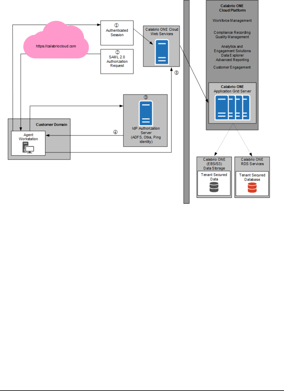
SAML Authentication Process Flow Diagram
This topic describes the process for SAML authentication.
All authorization and authentication of known user identities is managed by the customer within the
Identity Provider (Authorization Server) and outside of Webex WFO Cloud. Webex WFO acts as the
service provider (resource server) and consumes all user identities from the customer’s identity provider
(IdP). Known user identities that are active within the customer’s IdP are provided proper authorization to
access https://calabriocloud.com through a SAML authorization communication between the
customer’s IdP and Webex WFO’s Resource Server.
51
Data Transfer Flow Diagrams | SAML Authentication Process Flow Diagram
SAMLApproval process
Steps for SAMLauthentication:
1.
The user accesses https://calabriocloud.com; if the user has an authenticated session with the
IdP (Authorization Server), the user is allowed access.
2. If the user does not have an authenticated session, create a SAML Authentication Request and
redirect back to browser to the IdP (Authorization Server).
3. If the user is not already authenticated with the IdP (Authorization Server), the user is asked to log
in.
4. After the user successfully logs into the IdP, or if they were already logged in, the IdP sends a
redirect back to the browser with a SAML response.
5. Webex WFO validates the SAML response, receives the user’s information from the SAML
response, creates an authenticated session, and allows access.
52

Data Transfer Flow Diagrams | Recording Encryption
SAMLDenial Process
Steps for SAMLauthentication denial:
1. The user’s authentication access has been terminated in the IdP.
2. If the user does not have an authenticated session, create a SAML Authentication Request and
redirect back to browser to the IdP (Authorization Server).
3. Because the user is not authenticated with the IdP (Authorization Server), the user is asked to log
in.
4. The user is unable to authenticate with the IdP (Authentication Server), and is not authorized.
5. The user is denied access.
Recording Encryption
The following diagram describes the encryption of recordings in Webex WFO.
53

Data Transfer Flow Diagrams | Recording Encryption
All data is encrypted and transported via secured HTTPS/SSL from customer premise to Webex WFO for
processing and storage.
In Cloud deployments, the available encryption method is RSA-2048 (with asymmetric keys) and AES-
128.
In cloud deployment of Webex WFO, only the tenant (not Webex WFO Cloud Operations) controls the
keys used to encrypt recordings, and these keys are stored in the tenant’s database. In addition, a second
layer of encryption is embedded into Webex WFO, which Webex WFO Cloud Operations also does not
have access to.
54
